Available Online atwww.ijcsmc.com
International Journal of Computer Science and Mobile Computing
A Monthly Journal of Computer Science and Information Technology
ISSN 2320–088X
IMPACT FACTOR: 6.017IJCSMC, Vol. 7, Issue. 8, August 2018, pg.133 – 140
Design and Implementation of CMOS
8 Bit Segmented Current-Steering
DAC for High Speed Applications
Pratima M Angadi, Asst. Prof. Mahesh B Neelagar, Kumaraswamy K V
Department of VLSI Design & Embedded Systems, PG centre, VTU Belagavi, India Asst. Professor, Department of VLSI Design & Embedded Systems, PG centre, VTU Belagavi, India
Senior Technical Manager, Trident Techlabs Pvt. Ltd, Bangalore, India
[email protected]; [email protected]; [email protected]
Abstract— The paper presents 8-bit segmented current steering DAC. The segmentation includes design of 4-bit Thermometer encoded DAC and 4-4-bit Binary weighted DAC. Register, thermometer encoder, current bias, current source are the sub blocks used in this design. Current sources are designed in the form of matrix architecture in thermometer encoded DAC, and inputs are controlled by using decoding logic. Current sources are designed in the parallel style in binary weighted DAC, and inputs are controlled by using binary numbers. Compared to other DAC types, the Current Steering DAC consumes minimum power hence used in higher speed applications. The design of 8-bit segmented CSDAC is done using 130nm technology consumes 80mW of power; peak to peak current is 824.06uV and supply voltage 1.2V.
Keywords— segmentation, current steering, thermometer encoded DAC, binary weighted DAC, register, thermometer encoder, current bias, current source.
I. INTRODUCTION
II. METHODOLOGY
The design flow explains the methodology adopted for proposed DAC. Consists of 4 bit binary weighted current steering DAC and 4 bit generic/unary/thermometer encoded DAC in the position LSB and MSB respectively. Thermometer encoded CSDAC/unary/generic consists of array of current sources having a unit value I. when all inputs are zero than output current is also zero. Number of current sources are calculated by 2N -1. Inputs are controlled by using thermometer decoding logic. Here current sources are arranged in matrix form. It increases linearity of the DAC because there only singe bit changes at each stage. As bit complexity increases it is difficult to design encoder and complexity in the current source arrangement. Binary weighted consists of only N current sources of different sizes. Inputs are controlled by using binary numbers. Here current sources are arranged parallaly. It reduces the glitch in the output of DAC. It requires less area. In this methodology we adopted 50% segmentation that is 4-bit thermometer encoded as MSB bits and 4- bit binary weighted as LSB bits.
Fig.1: Design Flow
III. DESIGN AND IMPLEMENTATION
A. DESIGN OF 4–BIT BINARY WEIGHTED CSDAC
1.
INVERTER
It is a basic building block of all the design. Aspect ratio ( ) of pmos is ( ) and nmos is ( ), size of
pmos is always 2.5 times greater than nmos.
Fig.2: Schematic design of CMOS inverter
2. REGISTER
Fig.3: Schematic of register design
3. CURRENT BIAS
Biasing is used to fix quiescent point so that amplification of AC signal can be done to the required level. Current Mirror architecture is also called current biasing circuitry.
Fig.4: Current bias schematic design
4.
CURRENT CELL
As we already discussed in the second section as binary weighted CSDAC has different sizes of current value. We are placing this architecture in the LSB position the input starts from bit0, bit1, bit2 and bit3 has values I, 2I, 4I, 8I respectively. Higher sizes of current sources are designed by adding transistors parallaly in the switch section. iout and iout_neg are the outputs.
Fig.5: Row0 Fig.6: Row1
5. CURRENT ARRAY
The Current array schematic is a combination of current bias and the four different sizes current sources of binary weighted CSDAC. Implementation is done in the parallel way. The input is given to current array is binary numbers.
Fig.9 : Current array of binary weighted CSDAC
6. DESIGN OF 4-BIT BINARY WEIGHTED CSDAC
The design includes four inputs and two outputs which are complemented one. It requires four registers,
current array and four pairs of inverters to hold the logic.
Fig.10: Schematic of 4 bit binary weighted CSDAC
B. DESIGN OF 4–BIT GENERICCSDAC
7. THERMOMETER ENCODER
In the truth table B1 and T3 are MSB bits. The outputs T3, T2 and T1 solved by using K map, schematic is drawn based on obtained.
Table 1 Truth table
8. CURRENT ARRAY OF THERMOMETER ENCODED CSDAC
The design of current cell and register is same as binary weighted current CSDAC. Here value of current sources are same and arranged in the matrix form 16(4*4) current sources. It has three row inputs and three column inputs. Combination of current cell and current bias represented in the schematic.
Fig.12: Current array of thermometer encoded CSDAC
9. DESIGN OF 4-BIT THERMOMETER ENCODED CSDAC
Fig.13: Schematic of 4-Bit thermometer encoded CSDAC
Schematic of 4-bit thermometer encoded CSDAC consists of four registers for holding information, two thermometer encoders for decoding logic and current array. This is placed in MSB position of 8 bit segmented CSDAC.
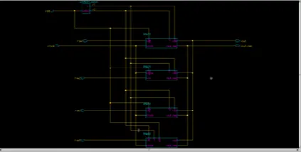
C. DESIGN OF 8-BIT SEGMENTED CSDAC
It is composed of binary weighted(LSB position), thermometer encoder(MSB position) and opamp in the final stage which is instrumentation amplifier converts current into voltage(2-voltage follower, 1-opamp).
Fig.14:8-bit segmented CSDAC
Table 2 Mentor Tools used
IV. RESULTSANDOBSERVATIONS
1. REGISTER MEASUREMENTS
Transient analysis of register is shown in the figure15. There is small delay between input and output, doesn’t affect circuit performance hence neglected. Clock frequency is 50MHz.
Fig.15: Register Waveforms
2. THERMOMETER ENCODER RESULTS
Transient analysis of encoder is shown in the figure16.
Fig. 16: Encoder Waveforms
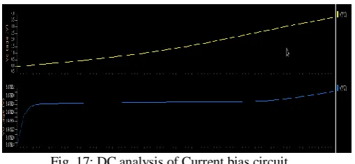
3. CURRENT BIAS MEASUREMENT RESULT
DC analysis of current bias is shown in the figure17.
Fig. 17: DC analysis of Current bias circuit
4. CURRENT CELL MEASUREMENTS
Fig.18: Transient analysis
5. MEASUREMENT RESULT OF 8-BIT SEGMENTED CSDAC
Fig.19: Transient analysis of 8 bit segmented CSDAC
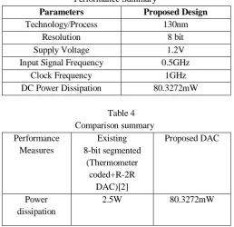
Transientanalysis of 8 bit segmented current steering DAC uses supply voltage 1.2V, provides peak to peak current 824.06uV and consumes 80mW of power. Clock frequency is 1GHz choose clock frequency to be double than input data frequency. Table 3 shows the performance summary of this design. Table 4 shows the comparison of power dissipation measurement with other DAC types. Table 5 shows comparison of percentage reduction in power with other DAC types.
Table 3 Performance Summary
Parameters Proposed Design
Technology/Process 130nm
Resolution 8 bit
Supply Voltage 1.2V
Input Signal Frequency 0.5GHz
Clock Frequency 1GHz
DC Power Dissipation 80.3272mW
Table 4 Comparison summary
Performance Measures
Existing 8-bit segmented
(Thermometer coded+R-2R
DAC)[2]
Proposed DAC
Power dissipation
Table 5
Percentage Reduction Comparison of Proposed DAC Proposed DAC Compared to Existing
8-bit segmented (Thermometer coded+R-2R
DAC)[2] Power dissipation 94%
V. CONCLUSIONS
The paper proposed, design of 8 bit segmented Current Steering DAC. Segmentation included design of four bit binary weighted CSDAC and four bit thermometer encoded DAC architectures in the LSB and MSB position respectively. Segmentation provides high accuracy, linearity in the DAC output and increases dynamic performance compared to usage of single architecture and DAC types in the design. Number of bits selection for segmentation is crucial. 94 percent power dissipation is achieved in proposed DAC.
The crucial part in the CSDAC is the design of current sources, as bits increases the area required to design current cells increases. It is possible to design 16bit and 32 bit DACs based on applications. But there is difficulty in the selection of decoding logic and current source design
R
EFERENCES
[1] A.Vanden Bosch, M. Borrenaus, M. Steyaert, W. Sansen, “A 10 bit 1G sample/s Nyquist current steering CMOS D/A converter”, IEEE, 2000.
[2] Samiran Halder, Hans Gustat, Christoph Scheytt, Andreas Thiede, “A 20GS/s 8 bit current steering DAC in 0.25um SiGe BiCMOS Technology”, IEEE, 2008.
[3] Piyush K. Mathurkar, Madan B. Mali, “CMOS 8-bit binary type current-steering DAC”, vol.2, IEEE 2012.
[4] Tyler Moody, Dr.Saiyu Ren, Dr.Robert Ewing, “10 bit current steering DAC in 90nm Technology”, IEEE,
2014.
[5] Arpit Kumar Baranwal, Anurag, Balwinder Singh,“Design and Analysis of 8 bit fully segmented digital to analog converter”, IEEE, 2015.