Technologies of Information and Telecommunications MARCH 27-31, 2005 – TUNISIA
Case Study: Design and Implementation of an
Ordering system using UML, Formal specification
and Java Builder
Abdellatif Tchantchane
United Arab Emirates University
Al Ain, United Arab Emirates
Phone : 971506731693
Email : [email protected]Abstract : This paper presents a case study of designing and implementing a sales ordering interactive system using the best practices for requirement analysis and design. We have used UML Use Case, Class, Sequence and State diagrams during requirement analysis and design. Formal methods is used to specify critical requirements and use cases. JBuilder development tool was used to implement the system. In this paper we highlight the best practices for software development and using the latest technology tools enabling us to develop a highly reusable components.
Keywords: UML, Use case diagram, Z notation, formal specification, Java
1. Introduction
The objective of this case study is to highlight the best practices of software development phases. We undertake the task of designing and implementing an interactive sales ordering system with the provision of a stock management tool. This paper will focus on the Unified Modeling Language (UML) as a tool for requirement specification and design. The focus also includes the use of formal methods for the specification of critical parts of the system. We have implemented the system using Object-Oriented language Jbuilder development tool.
UML is a modeling language using text and graphical notation for specifying, visualizing, constructing and documenting the analysis and the design phase of the system1,2. Use case, Class, Sequential and State diagrams are the main tools of UML. Use case diagrams are excellent to describe the problem domain requirements and communicating with users. The class diagrams show the entities with their internal structure and their relationship to other entities. Sequence diagrams describe how objects interact and communicate with each other. They focus on time. State diagrams describe the possible states a particular object can get into. The first two types of diagrams show the static of the model while sequence and state diagrams show the dynamic aspect of the system.
Formal methods consist of using mathematics to record as much of the development as is practical3,4. For the case study we are presenting in this paper, we have used the Z notation schemas for recording critical software specification and data design decisions. Z specification uses a combination of logic
and
elementary set theory.
2. Problem Statement Context
The case study is based initially on the following informal context specification: A computer store wants to acquire an automated tool for orders. The order is made on behalf of a registered customer. An order consists of a number of items in the stock. The system should keep track of the stock level of each item. The order is either pending or serviced. The first strategy is that an order is serviced only if the stock level meets the request. An invoice is made at the time of servicing the order. The second strategy is that an invoice is based on the current item prices (the time when the order is being serviced).
We consider further the following set of complementary requirements regarding placed and serviced orders:
1. An order may be placed by a single registered customer
2. A given customer may place a number of orders
3. An order may be deleted or edited before being serviced
4. An order must include at least one item (No null order).
5. A given item may not be selected more than once on the same order
6. A valid order must consist of at least one item. 7. The desired quantity of a placed item must not
be null.
8. An order is serviced when the customer is ready to pay the integral part o f the amount of a given order
9. The order can only be serviced if the number of units of each item ordered is in stock. 10. The customer can pay by cash or check 11. The credit card must be under the name of the
customer
12. The validity of the credit card must exceed at least two weeks the current date of the order servicing
13. The credit level must exceed the amount due of the order
3- Designing with UML notations
The ordering system was designed using Use Case, Class, Sequence and State diagrams offered by UML
.
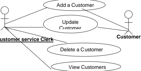
3.1.Use Case diagramFigures 1.a, 1.b and 1.c are respectively the Use Case diagrams for the system. The functionalities may be classified into 3 main subsystems: Customer registration, Inventory management and the purchasing subsystem. The purchase includes the billing. For each use case, besides describing the main happy scenario we have detailed all the exceptional scenarios. Include use cases are considered as reusable components.
Figure 1.a. Use Case diagram for Customer registration subsystem
Add a Customer
Delete a Customer
View Customers
Update
Customer
Customer
Customer service Clerk
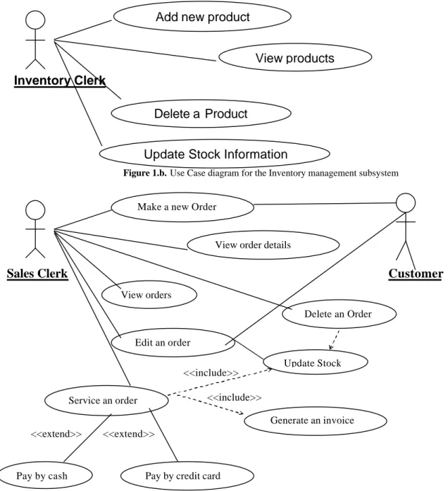
Figure 1.b. Use Case diagram for the Inventory management subsystem
Sales Clerk Customer
<<include>> <<include>> <<extend>> <<extend>>
Figure 1.c. Use case diagram for the purchasing subsystem
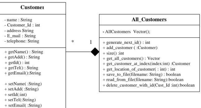
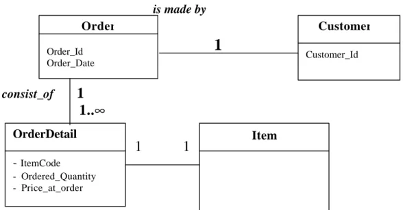
3.2. Class diagram
The class diagram is the most important entity in object-oriented design. It is very effective in showing what objects exist in the system and the static relationship between the classes. Figures 2.a, 2.b and
2.c display respectively the refined class diagrams for the customer management, the stock management and
the purchasing subsystem. The All_Customers,
All_Items and All_Orders are container classes based on the Standard Template Library vector. Figure 3.
displays the conceptual class diagram of the ordering systems. It shows the relationships, multiplicities, roles and the navigability between the various existing entities.
Add new product
Delete a Product
View products
Update Stock Information
Inventory Clerk
Make a new Order
View orders
View order details
Edit an order
Delete an Order
Service an order
Generate an invoice
Pay by cash Pay by credit card
* 1
Figure 2.a Class diagram for the customer management
* 1
Figure 2.b Class diagram of the stock management subsystem
Customer
- name : String - Customer_Id : int - address String - E_mail : String - telephone: String + getName() : String + getAdd() : String + getId() : int + getTel() : String + getEmail():String + setName( :String) + setAdd( :String) + setId(:int) + setTel(:String) + setEmail( :String)All_Customers
- AllCustomers Vector(); + generate_next_id() : int + add_customer ( :Customer) + size() :int + get_all_customers() : Vector + get_customer_at_index(index:int) :Customer + get_location_of_customer( : int) : int + save_to_file(filename: String) : boolean + read_from_file(filename: String):boolean + delete_customer_with_id(Cust_Id :int):booleanItem
- item_Code=-1:int {>0} - item_name : String - N_in_stock :int {>= 0} - price:float=-1 {>0} - N_ordered:int=0 {>=0} - Item_Description:String <<constructor>> public Item(nam:String,ItemCode, stoc,norder : int, price:float) + getCode():int + getName(): String + getStock():int + getPrice():float + getNordered():int + getDescription:String + setCode(int ) + setName(String nam) + setStock(int stoc) + setPrice(float pric) + setNordered(int norder) + setDescription(String desc)All_Items
- AllItems:Vector() + generate_next_Code():int + add_item(item: Item) + size() :int + delete_item_with_Code(:int):boolean + get_all_items() :Vector+ Item get_item_at_index(index:int) :Item + get_index_of_item_with_Code(:int) :int + replace(item : Item, index :int) :boolean + save_to_file(filename: String):boolean + read_from_file(filename : String):Boolean + set_add_Amount_ordered(itemCode , N_ordered :int):boolean + subtract_Amount_ordered(itemCode, N_ordered:int) :boolean add_to_stock( itemCode, newstock :int):boolean
subtract_from_stock(itemCode, stock :int):boolean
* 1
Figure 2.c Class diagram for the purchasing subsystem
is made by
•
1
•
consist_of
1
1..
∞
1 1
Figure 3. The conceptual class diagram of the Ordering Sale System
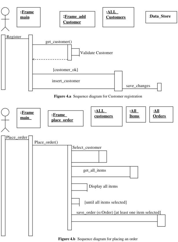
3.3.Sequence diagram
For each use case we constructed a sequence diagram depicting the collaboration in time and the overall flow of control in an object-oriented program.
Figure 4.a and figure 4.b illustrate the sequence diagrams used to capture the behavior of respectively the Adding a customer and the Placing an order use cases.
Order
Order_Id Order_DateCustomer
Customer_IdOrderDetail
-
ItemCode - Ordered_Quantity - Price_at_orderOrder
- order_id : int - cust_id : int - order_date : Date - invoice_date : Date - all_item_orders : Vector- state : State=Null {normal, pending, invoiced}
+ get_cust_id(): int + get_order_id() :int + get_number_of_items : int + get_order_date() : Date + get_invoice_date :Date {order_date ≤invoice_date} + getState() : State +get_item_order_at_index(:int): Item_Order +get_all_items_order() : Vector // +set_order_id(order_id:int) +set_cust_id(cust_id:int) +set_state(state:int) +insertItem(: Item_Order)
+delete_item_order(: Item_Order): boolean +set_order_date(:Date) +set_invoice_date(:Date)
All_Orders
-AllOrders:Vector() +add_order(:Order) +delete_order(:Order) +get_order_at(:int):Order +replace_order(:Order) +save_to_file(filename :String) +read_from_file(filename :String)Item
Register
get_customer() Validate Customer
[customer_ok]
insert_customer
save_changes
Figure 4.a Sequence diagram for Customer registration
Place_order Place_order() Select_customer
get_all_items
Display all items
[until all items selected]
save_order (o:Order) [at least one item selected]
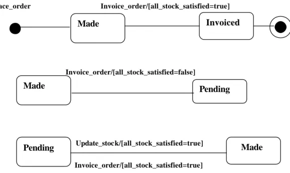
Figure 4.b Sequence diagram for placing an order 3.4 State diagram
The state diagram presented in figure 5 is constructed to show the different states of order how these state changes are triggered.
:Frame main
:Frame_add
Customer :ALL_ Customers :Data_Store :Frame main_ :Frame_ place_order :ALL_ customers :All_ Items :All OrdersPlace_order Invoice_order/[all_stock_satisfied=true] Invoice_order/[all_stock_satisfied=false]
Update_stock/[all_stock_satisfied=true]
Invoice_order/[all_stock_satisfied=true]
Figure 5. Various potential states and triggering events of the orderobject.
4. Formal Specification of critical tasks
Though formal specification is proven to be more useful for critical systems than for commercial development we described the critical transactions of
the system namely placing an order and generating invoice.
The formalization of the sales management system is given by the following
State schema:
Figure 6.a. State schema of the sales management system.
Made
Invoiced
Made
Pending
Pending
Made
DBSales
StockQuantity
:
Ν
Item
: ItemCode
ξ
StockQuantity
OrderedQuantity
:
Ν
+OrderDetail: Item
ξ
OrderedQuantity
Order
: Date
ξ
(Customer
→
P
OrderDetail)
All_customers
: P Customer
All_items
: P Item
All_orders
: P Order
dom(
OrderDetail
)
∈
all_items
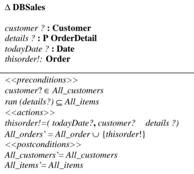
We also developed schemas based on Z notation for critical transactions such as removing an item from stock, placing a new order and generating an invoice.
Figure 6.b. illustrates the schema for placing a new order
.
Figure 6.b. The placing order specification schema.
5. User Interface Design
The Graphical user interface (UI) is designed using Jbuilder Personal 7th edition. The visual design tools provide an easy way to create a UI for a java application. The construction of the UI uses palettes that contain components such as buttons, text areas, lists, tables and menus. Action listener to component event such as mouse-click, keyboard and timers are generated automatically by Jbuilder. The corresponding event handler code is also easily attached to such actions. Most syntax, semantic and
declaration related errors are signaled while code is being written.
The designed UI provides interfaces for each of the following:
• Registering customers
• Keeping track of the items for sale
• Keeping track of the orders
• Generating invoice
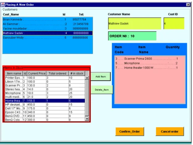
Figure 7.a is the screen shot of the customer registration interface while figure 7.b corresponds to placing a new order
.
∆
DBSales
customer ?
: Customer
details ?
: P OrderDetail
todayDate ?
: Date
thisorder!:
Order
<<preconditions>>
customer
?
∈
All_customers
ran (details?)
⊆
All_items
<<actions>>
thisorder!=( todayDate?
,
customer?
details ?)
All_orders’
=
All_order
∪
{
thisorder
!}
<<postconditions>>
All_customers’
=
All_customers
All_items’
=
All_items
Figure 7.a Screen shot of customer registration subsystem
Figure 7.b Screen shot for placing a new order
6. Data design
Customers, Items and Orders are persistent objects. We have based our access to these persistent objects on sequential files since it is very easy to read and write to text files. Noting that data access based on sequential text files has very limited capabilities such as allowing records to be retrieved in any order. In our case, all
persistent objects are provided at run time. Unique keys are generated for persistent objects created. Data integrity is assured by a set of rules such as a customer who has a made a given order to be serviced must not be deleted. We made a list of all possibilities that may cause inconsistency in the data. Such unwanted possibilities are prevented during system implementation.
Since this is a standalone type of application, security is not a major concern for us. But still the system is provided with a login password facility where no system utility may be accessed until the valid password is entered.
6.1 System Implementation
The system is implemented using an incremental approach. First the Customer registration is implemented. The code for the Customer class is generated directly from the class diagram. The container class is provided for all functionalities that are needed in such a way that the interface with the
GUI is made in a very straight manner. Using a very good naming strategy during the design has enabled us to implement the stock subsystem from the customer subsystem with very little modification. We believe this is due to the fact that we coded our entities as reusable components and because the system is designed using
UML class diagrams. Sequence diagrams have enabled us to clarify the interaction and the collaboration of not
only persistent objects but also the GUI frames required to achieve a single use case.
6.2Testing phase
Testing phase is the most critical one of the development process and is an integral part of every aspect of the development cycles. UML use case diagram were used to test against functional and exceptional cases. Though the testing method in isolation of the object order was not possible, UML state diagrams were used as a guideline where every transition is tested. Z notation schemas are used as formal documents for defining preconditions and post-conditions of every critical transaction by the system. Since this is an interactive system we have use the Java try catch exception handler around every input from user and for every type-conversion. This defensive approach prevents the system from crashing because of illegal inputs. The implementation of the invoice generation use case is given by figure 8.
7. Conclusion
We successfully implemented the Sales ordering system as described in this paper. The first lesson learned is thatUML use case diagrams are proven to be valuable for eliciting information about system functional requirements and communicating with potential users. They also helped to us distinct between functional and non-functional requirements. Use case diagrams were used during system verification stage to
test that all the functionalities are implemented. Class diagrams are used for the purpose of designing and implementing our system in an object-oriented approach. The code for persistent object was directly generated from their respective class diagrams. Formalization of the system state has helped us to rigorously understand the entities and relationships that may exist in the system. Future work relating to this system implemented based on UML design would be the investigation of what are the necessary modifications in case the system is changed from
sequential file based system to let’s say to Oracle database system.
References
1. G. Booch, J. Rumbaugh and I. Jacobson, The
unified Modeling Language User Gude, Addison
Wesley, 1999.
2. M. Fowler, UML Distilled:Applying the standard
object Modeling Notation, Addison Wesley, 1997.
3. J.B. Wordsworth, Software development with Z, Addison-Wesley (1992)
4. J.M. Spivey, The Z Notation : A reference manual, Prentice Hall International (1992).