JEEECCS, Volume 6, Issue 21, pages 39-48, 2020
A Novel Optical Fiber Transmission System
Using Duty-Cycle Modulation and Application
to ECG Signal: Analog Design and Simulation
Laurel Tatou Nguefack
Laboratory of Computer Science Engineering and Automation
UFD-SCI, ENSET, University of Douala Douala, Cameroon
Gutenbert W. Kenfack
Cameroun Telecommunications Yaoundé, Cameroon [email protected]
Félix Pauné
Laboratory of Computer Science Engineering and Automation
UFD-SCI, ENSET, University of Douala Douala, Cameroon
Jean Mbihi
Laboratory of Computer Science Engineering and Automation
UFD-SCI, ENSET, University of Douala Douala, Cameroon
Abstract – This paper focusses on a novel optical fiber transmission system, with application on human ECG signal. Its novelty relies on the use of a simple and high-quality DCM (duty-cycle modulation) circuit as the emitting interface. Then, the receiving device is a simple low-pass filter. A brief literature review on existing optical transmission systems is presented, for the sake of better understanding the scientific scope of the proposed optical signal transmission system. In addition, the corresponding architectural model is designed from a mix of analytical and advanced numerical tools. Furthermore, a prototyping DCM-based optical fiber transmission system, is implemented and well tested within Matlab/Simulink framework. As a relevant finding, when testing the transmission of an ECG modulating signal, the overall performance levels (e.g., SNR = 30 dB and RMS = 0.07), as well as the related hardware complexity and building cost, are more satisfactory compared to the capabilities of most popular optical fiber transmission systems. Thus, the DCM technology, might become an attractive and emerging research area, for the manufacturing of high quality and low-cost optical fiber signal transmission systems.
Keywords- optical fiber; Transmission system; ECG signal, duty-cycle modulation; design and simulation.
I. INTRODUCTION
Among most available signal modulation techniques, the Duty Cycle Modulation (DCM) is one of the latest issues initiated since 2005 [1]. A few years ago, it was the subject of a review article [2], in which the authors presented a variety of its main application areas. A sample of relevant examples are: analog-to-digital converters [3-5], digital-to-analog
converters [6-8], and power electronics drivers [9-14]. In the same pioneering paper [2], the authors stated that 6% of published research works were related to DCM-based signal transmission systems [15-16]. However, in all the research works presented in [15-16], the physical transmission media, considered between the emitter and the receiver, was an electrical line.
As a merit, the idea of using an optical signal transmission channel, with low cost DCM-based interfacing emitter and receiver, might brought an innovative architecture, in optical fiber signal transmission systems.
Nguefack Tatou Laurel, Paune Felix, Kenfack W. Gutenberg, Mbihi Jean
40
signal modulator, receiver (coherent or non-coherent), and more.
As it will be outlined later in Section II, these aforementioned weaknesses might explain the relevant merits of using DCM techniques, in optical signal transmissions systems, as it will be investigated in next sections of this paper.
The target modulating signal to be considered in this paper, is the human Electrocardiograms (ECG). Our choice relies on the fact that many research works available on ECG signals transmission, are mainly focused on popular modern technologies, e.g., Telephone Network [21], Bluetooth [22], Wireless [23-24], Mobile Network [25-26], and Internet of Things [27-28]. In addition, it is worth noting that in a distributed signal transmission network, the aforementioned modem transmission technologies, might coexist with DCM-based optical fiber channels. Each of which been dedicated to a target transmission sector, where its use is optimal in terms of building cost, environmental obstacles, size constraints,
building cost, and quality requirements. The relevant results obtained in the present work show the high transmission and reconstruction qualities of ECG waves.
The next section of this paper is organized as follows: In Section II, the methodology and tools used for the design and simulation of the DCM-based optical transmission system, is presented. Then, in Section III, the implementation works under Matlab/Simulink are outlined, and the simulation results are provided in section VI, and compared to those from existing optical transmission systems. Finally, the paper is concluded in Section V.
II. DESIGN METHODOLOGY AND TOOLS
The architecture of the optical transmission system proposed in this paper is shown in Figure 1. It consists of four subsystems, i.e., a) Duty-cycle modulator; b) Optical transmission channel, c) Conformer; d) Low-pass filter used as demodulator.
Figure 1. Schematic model of the proposed transmission system
A. ECG Signal
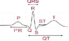
The ECG signal consists of a variety of electrical waves identified on its graphical profile, by a set of corresponding symbols, e.g., P (depolarization of the right and left atria), QRS (depolarization of the ventricles), and T (ventricular repolarization). Figure 2 shows a typical waveform of a GCE signal.
Figure 2. Graph of a virtual ECG signal and characteristic points
In practice, the characteristic quantities of an ECG signal vary from one person to another, and its interpretation is related to its intrinsic wave length. Therefore, its power spectral density varies according to the morphology of the signal. Following [29], this density is distributed in the frequency range 2-40 Hz.
B. Duty Cycle Modulator
The duty-cycle modulator belongs to the class of simple modulator circuits initiated and developed in [1]. The waveform of the duty-cycle modulated output signal is shown in Figure 3.
It behaves as a controlled relaxation oscillator, with control variable as the modulating input. Its well-known dynamic model, available in [3], is recalled in equation (1) given (2).
(
)
( ) ( ) (1 ) ( )
( ) ( ) ( )
( ) (t)
( ) 1 1
( ) ( ) ( ) m c m c c m
u t x t x t
t u t u t
x t Esign
du t
u t x t
dt
x t E
+ + = + − = − = = − + (1) 1 1 2 1 2
1 R , RC
R R
= = − = =
+ (2)
It is important also to recall on the basis of research works published in the literature, that a DCM signal denoted xm(t) and its relevant characteristics, i.e., duty cycle Rm(x(t)), modulation period Tof(x(t)), and positive pulse duration Tm(x(t)), are described as follows ([3-5]).
(
( ))
(
(
( ))
)
( ) on m mT x t
R x t
T x t
= (2)
(
)
(1 ) (1 )T ( ) ln
(1 ) ( 1)
on x E x t x E − − + = − + −
(3)
(
)
(
) (
)
(
) (
)
2 2
2 2
(1 ) (1 )
( ) ln
(1 ) ( 1)
m
x E
T x t
x E − + + = − − − (4)
The exact analytical expression of the duty-cycle modulation Rm(x(t)), originally established in [1], appears to be an intricate nonlinear function of x.
However, it has been proved that it is always possible to find its excellent linear approximation, in terms of precision and modulating range. As an available result, the equivalent linearized model of Rm(x(t)) defined earlier in Equation (3), is given in [ 3], by
(
)
1 2 2 1 1 1 (1 ) 1( ) ( ) , with
2 1
log 1
m m m
E
R x t p x t p
− = + = + − (5)
From equations (1) to (6), it can be seen that the modulating signal can be restored correctly using a suitable dimensioned low-pass filter. A static filter with gain given by (7) has been established in [15].
1 2 f m K p E = (6)
When the signal is modulated, it can be transmitted through the optical fiber canal. The effects of disturbance sources (laser, optical fiber and photoreceptor) on the modulated signal, might be the be cutoff by a downstream filter.
C. Optical Fiber Transmission
It is assumed here that a single optical fiber channel, has a maximum transmission rate of 1Mbits/s. In addition, the great emphasis here is more on attenuation and chromatic dispersion [30]. We have introduced also at the end of the transmission
channel, noise effects from optical line and electronic components.
The block diagram of the proposed optical transmission system shown in Fig. 4, is based on the works found in [30], [31], and is dimensioned according to IUT-T-G-652. It involves many physical quantities, e.g., standard attenuation, specific attenuation, chromatic dispersion, component noise power, and noise power. The standard attenuation denoted
a
dB is given by equation (8),10
10 log in
db out P a P = (7)
where, Pin stands for the transmitted power and Pout r being the received power.
The specific attenuation denoted
α
dB (in dB/Km) can be defined by (9), as a linear function of a standard attenuationa
dB (in dB)./
db
a
dbL
=
(8)The chromatic dispersion DLink (in ps/nm), as given by (10), is calculated from the chromatic dispersion coefficients D1550 at 1550 nm, provided by the optical fiber manufacturer.
1550
Link Link
D =L D (9)
The noise power component is the sum of powers due to shooting and thermal noises respectively. Both powers to be summed are defined in (11).
(
)
2
Power of shot noise = 2 Power of thermal noise in 4
n L d ph L
L B n
i R e I I B R
R k TBF
= + = (10)
The parameters containing in (11) are: RL (load resistance); e (charge of an electron); in (noise current), Id (dark current), Iph (current produced by the light beam), kB (Boltzmann Constant), T (temperature in Kelvin), B (bandwidth) and Fn (noise factor).
Finally, the total noise power is given by (12).
(
d ph)
Lb uitr 2e I +I B R +4k TBFnB
P = (11)
D. Active Low-Pass Filter
It is the demodulation module and consists of a second order low-pass filter, use for extracting the modulating ECG signal, which is encapsulated in the transmitted wave. Its transfer function defined in [32], is recalled here by (13).
(
)
2
3 4 2 3 3 2 4 2 3 3
( )
(1 ) 1
f M m f K x f s
x R R C C s R C R C K R C s
= =
+ + + − + (12)
Where 6
5 1 f R K R
= + (static gain), should be equal to (7),
according to (14).
5 6 1 1 2 f m R K
R p E
= + = (13)
Nguefack Tatou Laurel, Paune Felix, Kenfack W. Gutenberg, Mbihi Jean
42
2
2 2
( )
2
n f
n n
K f s
s s
=
+ + (14)
In which case, the natural frequency ωn (in rad/s) can be expressed as outlined by (16), as a function of ξ (damping factor of the filter) and fc (cut-off frequency of the filter) [3].
2 4 2
2
1 2
4
4
2
c n
f
=
−
+
−
+
(15)The set of equations (13)-(16), are useful for a better understanding of the DCM principle, within the DCM-based optical fiber transmission topology studied in this paper.
III. IMPLEMENTATION AND SIMULATION OF A PROTOTYPING TRANSMISSION SYSTEM FOR EGC WAVE
A. Matlab/Simulink Model
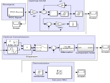
Matlab/Simulink model of the novel transmission system presented earlier in Figure 1 as a schematic diagram object, has been implemented under Matlab/Simulink framework as shown in Figure 4.
Table I shows the simulation data associated with a prototyping DCM-based optical fiber transmission system of ECG waves. The ECG source is an ECGSYN generator available in Matlab 2017a. Additional information about could be found in [33].
In addition, the duty cycle modulator model results from a direct transcription of the set of algebraic equations (1), using corresponding Matlab/Simulink blocks. Furthermore, the work carried out in [34] has been necessary for the optimization of DCM parameters. It is worth noting that Matlab/Simulink is equipped with a wide range of tools, allowing to appropriately model an optical fiber transmission channel according to a behavior dictated by equations (8)-(12). Finally, the demodulator is implemented as a transfer function block, with characteristics resulting from (13)-(16).
B. Virtual Simulation Data
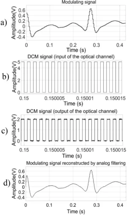
Table 1 lists all parameters used for the simulation of the proposed system, and Figure 6 shows the output signals of each subsystem of the proposed transmission system. Using these parameters, the values of the electronic components of the proposed system are deduced in accordance with equation (2) (13) (15) and Figure 1. For the DCM: R = 1.5KΩ, C = 1.1587nF, R1 = 10KΩ, R2= 60KΩ, Rb = 100Ω, Rp= 220Ω. For analog receiver: Re= 1MΩ, Ce= 0.01pF, Rc= 490Ω, Rd= 10Ω, R3= 17.949KΩ, R4= 145.48KΩ, R5=1.2477MΩ, R6= 188.06KΩ, C2= C3=10nF. An operational amplifier with a slew rate = 1000V/us is used.
JEEECCS, Volume 6, Issue 21, pages 39-48, 2020
TABLE I. SIMULATION DATASubsystem Elements operated Corresponding parameters
ECG source ECGSYN
generator -
Duty-cycle modulator
fm0 = 1 Mhz fmin
= 0.9 Mhz E=5V
Xmax=4V
α = 0.142857142857143
α2 =
0.857142857142857 τ = RC= 1.738029748389667*
10-06
Optical transmission
L=50km αdb/km = 0.28 db/km
τ = 1550nm
D1550 =17ps/nm.km
Iph = 1A
Id = 0.5*10-9 A
B = 40Ghz; RL=50KΩ
T = 300K; Fn = 1
Receiver gain = 20dB
adb =14 db
DDC = 850 ps/nm
Pnoise = 6.4*10-4 W
Demodulation low-pass filter
Pm=
0.086901487419555 fc = 110Hz and ξ =
1.5726 Shaping threshold =
0.1 V
ωn =
1.956946598924920 * 103 rad/s
kf =
1.150728289807124
IV. SIMULATION RESULTS AND DISCUSSIONS
Figure 5 shows the set of signals involved.
A. Time-domain analysis results and discussions
DCM-based optical fiber ECG transmission system. It is clear from Figure 5c and Figure 5c, that DCM modulated signals are affected by noise, through the optical fiber channel. However, the shape of the DCM modulated signal is unchanged. Even under the noisy transmission condition, Figure 5c shows that, the ECG wave is reconstituted with high precision, by the downstream demolition filter. In the appendix, we present the results obtained using electronic components of Matlab Simscape platform.
B. Frequency Domain Analysis Results and Discussions
Figure 7 presents the results of digital signal-to-noise ratio (SNR) analysis, of signals visualized above in Figures 5a-5d respectively. In this context, the SNR is only meaningful, for the modulating input (Figure 7a) and demodulated response (Figure 7d). In both cases, the resulting spectra are quite similar, and the computed SNR is 30 dB. This is a very good performance compared to that of some existing optical fiber transmission topologies, as it will be pointed out in the next subsection. Moreover, the value of the RMS error is less than 0.0695907.
Figure 5: Signals from the virtual prototype of the proposed transmission system
Nguefack Tatou Laurel, Paune Felix, Kenfack W. Gutenberg, Mbihi Jean
44
Figure 7:Power spectra of the signals in Figure 5
Even in term of quality, the DCM-based solution remains a very attractive candidate. Indeed, in [39], the SNR performance is 7 dB for the transmission channel, with a BER of 1.5 x 10⁻⁵. Similarly, in [40], the SNR for ECG signal transmitted via a Bluetooth link is in the order of 26 dB. These indicators levels are significantly lower, compared to 30 dB SNR obtained in this paper.
C. Comparison Of DCM-Based Optical ECG Transmission Systems with Other Architectures
A first comparison criterion between optical ECG transmission systems, is the hardware architecture of the transmitter and receiver circuitries. Table II presents a comparison of a sample of existing optical transmission architectures, with the novel building scheme initiated in this paper. It is worth noting in Table II that the hardware architectures offered by all optical fiber transmission systems, are notoriously complex [35-38]. As an implication, our novel DCM-based optical fiber transmission architecture is optimal in terms of structural simplicity, analytically defined characteristics, ease of understanding, as well as low realization cost.
CONCLUSION
The simulation results presented in this paper, has proved the feasibility, as well as high qualities and impact factor, of the proposed DCM-based optical fiber signal transmission architecture. However, a number of additional future research works, will be conducted in order to transform that novel signal transmission architecture, into social an industrial reality. As an implication, it will be interesting in future scientific works to realize a first patentable prototype. Moreover, given a wide variety of human biological signals, e.g., ECG, EMG, EPG, temperature and voice, it would be fruitful to extend the actual single channel architecture, to multichannel optical fiber transmission topology. Finally, it will be more beneficial to interconnect DCM-based optical fiber transmission system, with latest digital communication network technologies.
TABLE II. HARDWARE COMPARISON WITH A SAMPLE OF EXISTING TOPLOGIES OF OPTICAL TRANSMITTER AND DCM
Ref. Optical transmitter Passive
components
integrated circuits
[36] 15 02
[37-38] 08
02
DCM 04 01
APPENDIX: ELECTRICAL MODEL OF THE
NOVEL DCM-BASED OPTIC FIBER
TRANSMISSION SYSTEM
Nguefack Tatou Laurel, Paune Felix, Kenfack W. Gutenberg, Mbihi Jean
46
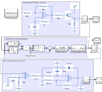
Figure 8. Electronic model of the proposed DCM-based optimal fiber transmission
system
Figure 9. Waveforms of an electrical circuit model of the novel optic fiber transmission system, simulated in Matlab/Simscape platform
CONTRIBUTION OF AUTHORS
Laurel Tatou Nguefack contributed to the research of scientific references used to edit the introduction of the paper. He also contributed to the development of the research methodology, as well as to the design and implementation under Matlab/Simulink, of a reliable model of the prototyping DCM-based optical fiber transmission system, with successful application to
FélixPauné contributed to the specifications of scientific information, and technical data as summarized in Table I, required for successfully dimensioning and simulating the overall prototyping DCM-based optical fiber transmission system.
Gutenbert W. Kenfack, contributed to the comparative study between the proposed DCM-based optical fiber transmission system, and other existing optical fiber signal transmission topologies, as summarized in Table II.
Jean Mbihi contributed to the scientific organization, supervision, evaluation and revisions of research works presented in this paper. He contributed also, as the corresponding author, to the preparation and submission of the first manuscript to JEEECCS reviewing process. In addition, he expertized in depth the basic revised paper edited by the main author, for the sake of last evaluations. As additional works, he brought numerous improvements in the whole content, including, identification and correction of both semantic and grammatical problems, key words updating, and integration of additional comments. He produced also the final revised paper, submitted to JEEECCS for publication.
REFERENCES
[1] J. Mbihi, B. Ndjali, and M. Mbouenda, ''Modelling and simulation of a class of duty-cycle modulators for industrial instrumentation'', 2005.
[2] L. N. Nneme, B. M. Lonla, G. B. Sonfack, and J. Mbihi, ''Review of a Multipurpose Duty-Cycle Modulation Technology in Electrical and Electronics Engineering'', Journal of Electrical Engineering, Electronics, Control and Computer Science, vol. 4, no 2, p. 9‑18, oct. 2018
[3] Mbihi, F. Ndjali Beng, martin kom, and L. Nneme Nneme, ''A Novel Analog-to-digital conversion Technique using nonlinear duty-cycle modulation'', International Journal of Electronics and Computer Science Engineering, vol. 1, No 3, pp.818-825, 2012.
[4] J. Mbihi and L. N. Nneme, 'A Multi-Channel Analog-To-Digital Conversion Technique Using Parallel Duty-Cycle Modulation''', International Journal of Electronics and Computer Science Engineering, vol. 1, No 3, pp. 826-833, 2012.
[5] Sonfack Gisèle Béatrice1, Mbihi Jean, ''FPGA-Based Analog-to-Digital Conversion via Optimal Duty-Cycle Modulation'', Electrical and Electronic Engineering 2018, 8(2): 29-36, 2018.
[6] B. Moffo Lonla, J. Mbihi, L. Nneme Nneme and M. Kom. ''A Novel Digital–to–Analog Conversion Technique Systems and Signal processing, Vol 7, No 1, pp 42–49-8, 2013using Duty-Cycle Modulation,'' . International Journal of Circuits [7] B. Moffo Lonla and J. Mbihi. ''Novel Digital Duty–Cycle
Modulation Scheme for FPGA- Based Digital-to-Analog Conversion'', IEEE Transaction on circuits and system II, Vol 62, No 6, pp. 543–547, 2015.
[8] B. Moffo Lonla, J. Mbihi and L. Nneme Nneme, ''FPGA-based Multichannel Digital Duty-cycle modulation and Application to simultaneous generation of Analog Signals'', Journal of Electronic Design Technology, Vol. 8, Issue 21, pp. 23-35, 2017.
[9] Y. P. Dangwe Soulemanou, J. Mbihi, H. Djala, J. Effa, ''Virtual digital control scheme for duty-cycle modulation Boost converter,'' Journal of computer science and control systems, Vol 10, No 2, pp. 22-27, 2017.
[10] J. Mbihi L. Nneme Nneme, ''A novel control scheme for buck power converters using duty cycle modulation.'' International Journal of power electronics, © Inderscience Enterprises Ltd, volume 5, No 3/4, pp. 185-199, 2013
[11] Y. P. Dangwe sounsoumou, Haman-Djalo; J. Mbihi and J. Y. Effa, ''Modélisation et simulation virtuelle d’un nouveau schema de réglage de hacheurs boost à commande rapprochée par modulation en rapport cyclique.'' Afrique Sciences, Volume 13, No 1, pp. 176-185, 2017.
[12] Y. P. Dangwe sounsoumou, J. Mbihi, Haman-Djalo; and J. Y Effa,. ''Virtual digital control scheme for duty cycle modulation boost converter. '' Journal of Computer Science and Control Systems, Volume 10, No 2, pp. 22-27, October 2017.
[13] A. Obono Biyobo, L. Nneme Nneme and J. Mbihi, ''A novel sine duty cycle modulation control scheme for photovoltaic single phase power inverters. '' WSEAS Transactions on Circuits and Systems, volume 17, pp. 107-113; 2018, [14] J. Mbihi, ''Dynamic Modelling and Virtual Simulation of
Digital Duty-Cycle Modulation Control Drivers'', International Journal of Electrical, Computer, Energetic, Electronic and Communication Engineering Vol:11, No:4, 2017.
[15] Leandre Nneme Nneme, Jean Mbihi, '' Modeling and Simulation of a New Duty-Cycle Modulation Scheme for Signal Transmission Systems'', American Journal of Electrical and Electronic Engineering, 2014, Vol. 2, No. 3, 82-87 [16] B. Lonla Moffo, J. Mbihi, L. Nneme Nneme, '' A Low Cost
and High Quality Duty-Cycle 'Modulation Scheme and Applications'', International Journal of Electrical, Computer, Energetic, Electronic and Communication Engineering Vol:8, No:3, 2014
[17] A. F. Elrefaie, J. K. Townsend, M. B. Romeiser, and K. S. Shanmugan, « Computer simulation of digital lightwave links », IEEE Journal on Selected Areas in Communications, vol. 6, no 1, p. 94–105, 1988.
[18] K. Mishina, D. Hisano, and A. Maruta, « All-Optical Modulation Format Conversion and Applications in Future Photonic Networks », IEICE Transactions on Electronics, vol. 102, no 4, p. 304–315, 2019.
[19] P. Šalík, F. Čertík, and R. Roka, « Duobinary modulation format in optical communication systems », Advances in Signal Processing, vol. 3, no 1, p. 1–7, 2015.
[20] L. N. Binh, Optical fiber communication systems with Matlab and Simulink models. CRC Press, 2014.
[21] M. Engin, E. Çağlav, and E. Z. Engin, « Real-time ECG signal transmission via telephone network », Measurement, vol. 37, no 2, p. 167‑171, mars 2005, doi: 10.1016/j.measurement.2004.11.001.
[22] P. L. Penmatsa and D. V. R. K. Reddy, « Smart Detection and Transmission of Abnormalities in ECG via Bluetooth », in 2016 IEEE International Conference on Smart Cloud (SmartCloud), 2016, p. 41‑44, doi: 10.1109/SmartCloud.2016.10.
[23] N. Li and al., « Design of Portable Wireless Electrocardiogram Monitoring System », in Journal of Physics: Conference Series, 2020, vol. 1438, p. 012009. [24] N. F. Güler and U. Fidan, « Wireless Transmission of ECG
signal », J Med Syst, vol. 30, no 3, p. 231‑235, juin 2006, doi: 10.1007/s10916-005-7980-5.
[25] E. Eşme and F. Ünsaçar, « DESIGN OF REMOTE CONTROLLED HEART MONITORING SYSTEM », LIFE: International Journal of Health and Life-Sciences, vol. 5, no 1, 2019.
[26] Q. He, J. Wang, G. Zhao, D. Chen, Y. Ju, and K. Zhao, « The Implementation of ECG Monitoring Medical System based on Mobile Platform », in Journal of Physics: Conference Series, 2019, vol. 1168, p. 032055.
[27] H. Ozkan, O. Ozhan, Y. Karadana, M. Gulcu, S. Macit, and F. Husain, « A Portable Wearable Tele-ECG Monitoring System », IEEE Transactions on Instrumentation and Measurement, vol. 69, no 1, p. 173‑182, janv. 2020, doi: 10.1109/TIM.2019.2895484.
[28] I. Nouira and M. H. Said, « Smart ECG Monitoring Through IoT », in Smart Medical Data Sensing and IoT Systems Design in Healthcare, IGI Global, 2020, p. 224–246. [29] N. V. Thakor, J. G. Webster, and W. J. Tompkins, «
Nguefack Tatou Laurel, Paune Felix, Kenfack W. Gutenberg, Mbihi Jean
48
QRS filter », IEEE Transactions on biomedical engineering, no 11, p. 702–706, 1984.
[30] F. Certik and R. Roka, « Analysis of modulation techniques utilized in the optical transmission medium », in 2012
ELEKTRO, 2012, p. 30‑35, doi:
10.1109/ELEKTRO.2012.6225603.
[31] R. Hui, Introduction to Fiber-Optic Communications. Elsevier Science, 2019.
[32] S. T. Karris, Signals and Systems with MATLAB Computing and Simulink Modeling. Orchard Publications, 2007. [33] J. Pan and W. J. Tompkins, « A real-time QRS detection
algorithm », IEEE Trans. Biomed. Eng, vol. 32, no 3, p. 230– 236, 1985.
[34] G. Sonfack, J. Mbihi, and B. Lonla Moffo, « Optimal Duty-Cycle Modulation Scheme For Analog-To-Digital Conversion Systems », janv. 2018, doi: 10.5281/zenodo.1315523. [35] B. N. Mohapatra, M. Jonaid, and A. Routray, « Audio
Transmitter and receiver System using Fiber Optic Cable », International Journal of Emerging Technologies in Engineering Research (IJETER), vol. 5, no 5, 2017. [36] R. Raza and S. A. Hayat, « Design and Study of an Optical
Fiber Digital Transmitter », Information Technology Journal, vol. 5, no 3, p. 433–438, 2006.
[37] L. A. D. Van Den Broeke, L. P. De Jong, J. Davidse, and A. H. M. Van Roermund, « A low-cost multichannel optical transmission system for video signals », IEEE Transactions on Communications, vol. 43, no 9, p. 2493‑2501, sept. 1995, doi: 10.1109/26.412724.
[38] D. Sacko and A. A. Kéïta, « Techniques of Modulation: Pulse Amplitude Modulation, Pulse Width Modulation, Pulse Position Modulation », International journal of Engineering And advanced Technology, vol. 7, no 2, p. 100‑108, déc. 2017.
[39] D. R. Dhatchayeny, A. Sewaiwar, S. V. Tiwari, and Y. H. Chung, « EEG biomedical signal transmission using visible light communication », in 2015 International Conference on Industrial Instrumentation and Control (ICIC), 2015, p. 243‑246, doi: 10.1109/IIC.2015.7150746.