INSTALLATION
MANUAL
Security Control Panels
Issue 2
Contents Premier 24 Installation Manual
Contents
1. System Overview... 4 System Architecture ... 4 Control Panel ... 4 Remote Keypads... 4 Zone Expanders... 5 Output Expander... 5 Communicators ... 5 Other Devices ... 5 2. Installation ... 6 Installation Sequence... 6 Control Panel ... 6 Connecting AC Mains... 9 Connecting Batteries... 9Connecting Devices to the Network ... 10
Remote Keypads... 12
4XP Zone Expander ... 13
8XE Zone Expander... 13
8XP Zone Expander ... 14
24XID Zone Expander ... 15
OP16 Output Expander... 16
Zone Connections ... 17
Auxiliary Tamper Connections... 18
Speaker Connections ... 18
External Sounder Connections ... 18
Panel Outputs 1 - 6 and PG1... 19
Plug-on Digimodems ... 20 RP9 Radio-Pad... 21 GSM Module... 21 PC-Com... 21 UNI-Com... 21 PRINT-Com... 21 GSM-Com... 22 NET-Com... 22 Connecting a Computer ... 22 Connecting a Printer... 22
3. Commissioning and Troubleshooting .... 23
Commissioning... 23
Trouble-Shooting... 23
Reset and Service Messages... 25
4. Factory Defaults ... 26
5. The Programming Menu ... 28
Introduction... 28
6. Programming the Control Panel... 30
Introduction... 30
Log Off Engineer... 30
Reset the Engineers Code (User 00)... 30
6.1 Zone Setup ... 31
Zone Types ... 32
Zone Attributes 1 ... 33
Zone Attributes 2 ... 33
Attributes for Moment or Latch Keys ... 34
Zone Text... 34
Zone Wiring Type... 34
DD 243:2002... 34 6.2 Arming Options... 35 Timers ... 35 Arming Modes... 36 Options... 36 6.3 Global Options ... 39 System Timers ... 39 System Config. ... 40 System Options ... 42 Monitor Hardware... 42 Control Timers ... 43 System Text ... 43 Speaker Tones... 44 6.4 Keypad Setup... 45
Keypad Zone Mapping ... 46
Keypad Options ... 46
Keypad Speaker Volume... 46
Keypad Sounder Options... 46
6.5 Expander Setup ... 47
Expander Auxiliary Input ... 48
Expander Speaker Volume... 48
Expander Sounder Options... 48
6.6 System Outputs ... 49
Available Outputs ... 50
Programming Outputs... 50
Output Group - Not Used ... 50
Output Group - System ... 50
Output Group - Alarm ... 51
Output Group - Zone ... 53
Output Attributes ... 53
Custom Output (PGM5-8)... 53
6.7 UDL/Digi Options ... 54
Reset Digi... 54
Start Test Call ... 54
Program Digi... 55
Digi Options ... 58
UDL Options... 59
Radio/SMS Options ... 61
Com Port Setup ... 61
Premier 24 Installation Manual Contents
6.8 Setup Users...67
Adding New Users to the System ... 68
Programming New Users... 68
User Types ... 68
User Options ... 69
User Name Text... 69
Programming Proximity TAGS ... 69
Deleting User Codes... 69
Available Options... 70
6.9 Engineer Utilities ...71
View Event Log... 71
Do Bell Test ... 73
Do Walk Test ... 73
View Zone Status ... 74
View Version No ... 74
Confirm Devices... 74
View RKP Status... 74
Check Exp. Status... 75
Set System Time ... 75
Set System Date... 75
Change Eng. Code... 75
6.10 Programming Part Arms ...76
Alter Part Arms... 76
7. Specifications ...77 Control Panel ... 77 Remote Keypads... 78 Zone Expanders ... 78 Output Expanders ... 79 Communicators... 79 Standards ... 80 Warranty ... 80
8. Quick Reference Guide ...82
1. System Overview
2. Installation
3. Commissioning & Troubleshooting
4. Factory Defaults
5. The Programming Menu
6. Programming the Control Panel
6.1. Zone Setup 6.2. Area Programming 6.3. Global Options 6.4. Keypad Setup 6.5. Expander Setup 6.6. Output Setup 6.7. UDL/Digi Options 6.8. Setup Users 6.9. Engineer Utils
6.10. Programming Part Arms
7. Specifications
System Overview Premier 24 Installation Manual
1. System Overview
System Architecture
Speaker Output 6 Programmable 100mA OutputsBell Tamper Input Auxiliary Tamper Input
Premier 24
Premier LCD/LCDP Keypad 4 Wire Data Network
16 Programmable 100mA Outputs Premier OP16 Output Module 8 Zone Inputs Alarm Receiving Centre Modem
PC and Modem for Remote Upload/Download
PC-Com
PC and for Local Upload/DownloadPC-Com
Plug on Digimodem Plug on (Com300, Com2400 or ComISDN) GSM Module 2 Zone
Inputs 1Programmable100mA Output 2 Zone
Inputs 1Programmable100mA Output
Speaker Output 8 Zone Inputs Auxiliary Input Premier 8XP Zone Expander 8 Programmable 100mA Outputs Power Info. Ready Serv ice Omi Power Info. Ready Serv ice Omit Bell Output Area Yes Part Chime Omit Reset Menu 2 abc No 1 3 def 6 mno 9 wxyz 5 jkl 8 tuv 0 4 ghi 7 pqrs Area Yes Part Chime Omit Reset Menu 2 abc No 1 3 def 6 mno 9 wxyz 5 jkl 8 tuv 0 4 ghi 7 pqrs Premier 2 Zone Inputs Power Ready Serv ice Omit Area Yes Part Chime Omit Reset Menu 2 abc No 1 3 def 6 mno 9 wxyz 5 jkl 8 tuv 0 4 ghi 7 pqrs 1 2 3 4 5 6 7 8 9 10 11 12 13 14 15 16 Power Ready Omit Serv ice
Premier 8XE Zone ExpanderPlug-on
Strobe Output 1 x PGM Output
Control Panel
Premier 24
• 8 fully programmable Single Pole + Global Tamper or End Of Line zones
• Expandable to 24 zones via keypads and zone expanders • Up to 4 keypads
• Up to 2 expanders (2 remote or 1 local and 1 remote) • Up to 1 output module
• 4-wire data network (standard 7/0.2 alarm cable) • Full arm plus 3 part arms
• Shunt group
• 16 programmable User codes • 500 Event Log (time & date stamped) • 16 character zone text
• 9 programmable outputs (100mA each)
• Facility for Plug-on Digimodem (Com300, Com2400 or
ComISDN)
• Facility for Plug-on GSM Module
• PC-Com/printer port
Remote Keypads
Premier LCD
• 32 character text display
• 2 fully programmable DP or EOL zones
• 1 fully programmable output (100mA -ve applied) • Fully adjustable back-lighting, normally bright, dim or off,
changing to bright during entry or following a key press • Built in piezo sounder
• Programmable ‘Info.’ LED
Premier LCDL
ALL the features of the Premier LCD plus: • Larger 32 character text display • Speaker output
Premier LCDP
• LCD keypad with a built in Proximity Tag Reader
Premier LCDLP
• LCDL keypad with a built in Proximity Tag Reader
Premier RKP8/16Plus
• LED Arming keypad
• 2 fully programmable EOL zones • CANNOT be used for Programming
Premier 24 Installation Manual System Overview
Zone Expanders
Premier 4XP
• 4 fully programmable DP or EOL zones
• 2 fully programmable outputs (100mA -ve applied each) • Remotely wired unit
Premier 8XE
• 8 fully programmable SP or EOL zones • Plug-on unit
Premier 8XP
• 8 fully programmable DP or EOL zones
• 8 fully programmable outputs (100mA -ve applied each) • Speaker output
• Programmable auxiliary input • Remotely wired unit
Premier 24IXD
• 1 loop x 24 fully programmable iD zones • iD biscuit technology
• Plug-on unit for Premier 24 only
“iD” is a registered trade mark of Chloride Safety System Limited.
Output Expander
Premier OP16
• 16 fully programmable outputs (100mA each) • 1 fault output (100mA -ve applied)
• Can be connected to relays and internal sounders
Premier RM8 Relay Module
• Plug-on relay card (RedCARE footprint) • 8 separate inputs for stand alone operation • 8 x 3Amp relay outputs (n/o, n/c, com) • Output ‘ON’ LED indication
Communicators
Com300
• 8 channel digital communicator supportingFast Format, Contact ID, SIA Level II and EasyCom Pager protocols • 300-baud modem for remote uploading and
downloading using the Wintex UDL software and a PC • For use with an analogue telephone line (REN = 1)
Com2400
• 8 channel digital communicator supporting Fast Format, Contact ID, SIA Level II and EasyCom Pager and SMS Messaging protocols
• 2400-baud modem for remote uploading and downloading using the Wintex UDL software and a PC • Sends SMS text messages to mobile phones
• For use with an analogue telephone line (REN = 1)
ComISDN
• 8 channel digital communicator supportingFast Format, Contact ID, SIA Level II and EasyCom Pager protocols • 300-baud (analogue) or 19200-baud (digital) Modem
for remote uploading and downloading using the
Wintex UDL software and a PC • For use with an ISDN telephone line
RP9 Radio-Pad
• 8 channel Paknet radio communicator supportingFast Format and Contact ID protocols
• 4800-baud modem for remote uploading and downloading using the Wintex UDL software and a PC
GSM Module
• True GSM telephone line backup
• Sends SMS text messages to mobile phones
• Arm, Disarm, Reset the alarm, turn outputs on and off, omit zones and send messages to the control panel using SMS text messages
• 9600-baud modem for remote uploading and downloading using the Wintex UDL software and a PC
Other Devices
PC-Com/USB-Com
• For connecting a PC to the control panel allowing local uploading and downloading using Wintex UDL software
UNI-Com
• For connecting a serial device i.e. PC modem or mobile phone to the control panel
PRINT-Com
• For connecting a serial printer to the control panel
RPD-Com
• For connecting a RP9Radio-Pad to the control panel
GSM-Com
• For connecting a GSM Module to the control panel
NET-Com
Installation Premier 24 Installation Manual
2. Installation
Installation Sequence
Before attempting to install the alarm system, read this section. Once you have an overall understanding of the installation sequence, carefully work through each step.
1: Design the Layout
Make a rough sketch of the premises to get an idea of where the alarm detection devices, keypads, zone expanders etc. are to be located.
2: Mounting the Panel
The control panel should be mounted in a dry area close to an unswitched AC power source and the incoming telephone line (if using the digimodem).
!"
You must complete all wiring before connecting thebattery or applying AC mains to the control panel.
3: Install the Keypads and Zone Expanders
Mount and connect the keypads, zone expanders and output modules to the control panel (see page 10 for details).
4: Install the Alarm Detection Devices
Install the detection devices, PIR’s, Contacts, PA Buttons etc. and connect them to the control panel (see page 17 for details).
5: Install the External Sounder
Install the external sounder and connect to the control panel (see page 18 for wiring details).
6: Other Wiring
Complete all other wiring including speakers, telephone line and output connections etc. (see pages 18 - 20 for details).
7: Applying Power to the Control Panel
Once steps 1 to 6 are completed, power can be applied to the control panel.
When applying power for the first time, the factory default settings must be loaded (see page 23 for details). Power should always be connected in the following order:
• Connect the red battery lead to the positive terminal of the battery and then connect the black battery lead to the negative terminal
!"
The panel will only become ‘live’ when the ACMains is connected or the ‘Battery Kick-start’ button is pressed.
• Connect the AC mains
For a complete list of factory default settings, see page 26.
8: Programming the control panel
Please refer to section 5 for instruction on programming the control panel.
9: Testing the System
Test the system thoroughly to ensure that all features and functions operate as required (see page 73 for details).
Control Panel
Mounting
Mount the control panel on a flat, plumb wall using at least three screws of appropriate size.
!"
It is essential to ensure that none of the fixing slots orcable entries are accessible after fixing.
Mains cabling must be secured (e.g. with a cable tie) to one of the anchor points provided.
Wiring the Control Panel
WARNING: ELECTRICITY CAN KILL
BEFORE connecting the control panel ALWAYS disconnect the supply at the consumer unit. If in ANY doubt consult a qualified electrician.
!"
ONLY connect the mains supply to the mains terminalblock, NEVER connect the mains supply directly to the PCB.
ALWAYS refer to National Wiring Regulations when conducting installation.
An appropriate and readily accessible disconnection device (e.g. an unswitched fused spur) MUST be provided as part of the installation.
The disconnection device must NOT be fitted in a flexible cord.
Where identification of the neutral in the mains supply is NOT possible a two-pole disconnection device MUST be used.
The building mains supply MUST incorporate appropriate short-circuit backup protection (e.g. a fuse or circuit breaker) of High Breaking Capacity (HBC, at least 1500A).
Use mains cable of adequate carrying capacity for the rated current (i.e. at least 0.75mm2).
Premier 24 Installation Manual Installation
Control Panel Layout
Aux 12V +B att A. C .
Battery Bell Network
F5 F2 F3 F4 Engineer Remote Com2 JP6 Com1 Load Defaults Tx2 Rx2 Tamp Strb 0V Bell+12V Pg 1 Aux 12V Spk -+ -Aux Tamp
Installation Premier 24 Installation Manual
Control Panel PCB Layout
Aux 12V Tamp Strb 0V Bell+12V Pg 1Spk - Aux12V +Ba tt A. C .
Battery Bell Network
F5 F2 F3 F4 Engineer Remote Com2 JP6 Com1 Load Defaults Tx2 Rx2 JP9 + - Aux Tamp 1: AC Input
Connected to the 16.5V transformer.
#"
DO NOT CONNECT THE MAINS SUPPLY TO THE ACINPUT TERMINALS ON THE PCB. 2: Battery Connections
A 12V rechargeable battery must be connected to these terminals in order to provide continuous system operation in the event of an AC Mains failure (see page 9 for details). 3: Network Data Indicators
The red LED indicates that data is flowing out of the control panel and normally flashes very quickly. The green LED indicates that data is flowing into the control panel and normally flashes slowly, the green LED flashes faster as more devices are connected (see page 10 for details). 4: External Sounder Connections
These terminals are used for connecting to an external sounder unit and is protected by a 900mA PTC – F2 (see page 18 for wiring details).
5: Network Connections
The Network provides connection for the keypads and zone expander. The ‘+’ and ‘–’ terminals provide power (protected by a 900mA PTC – F3) whilst the ‘T’ transmits data and ‘R’ receives data (see page 10 for wiring details). 6: PG1
PG1 is a low current (100mA ‘-ve’ applied) output (see page 19 for wiring details). The output is also fully programmable (see page 50 for programming details).
7: SPK- Loudspeaker Connection
These terminals can be used for connecting up to one 16Ω
or two 8Ω loudspeakers (see page 18 for wiring details).
8: Auxiliary 12V Power
These terminals are for connecting devices that require 12V power (protected by a 900mA PTC - F4).
9: Auxiliary Tamper Connections
These terminals can be used for monitoring the box tamper of auxiliary devices such as power supplies etc. (see page 17 for wiring details).
10: Programmable Zones 1 - 8
These terminals provide the connections for the 8 zones (see page 17 for wiring details). Each zone is also fully programmable (see page 31 for programming details). 11: Expansion Port
The expansion port is used for plugging on a local zone expander (see page 13 for details).
12: Communication Port 2
Com Port 2 is a serial communications port and can be used for connecting a GSM Module.
13: Plug-on Digimodem Connections
This socket provides connection for a Com300, Com2400 or
ComISDN digimodem (see page 20 for details). 14: Digicom Power & Inputs
These terminals provide +12V power (unfused), a remote reset input and a line fault input and would normally be used when connecting a stand-alone communicator to the control panel (see page 19 for wiring details).
15: Panel Outputs
Outputs 1 to 6 are low current (100mA ‘-ve’ applied) and would normally be used when connecting a stand-alone communicator to the control panel (see page 19 for wiring details). Each output is also fully programmable (see page 50 for programming details).
Premier 24 Installation Manual Installation 16: Box Tamper Connection
The box tamper micro switch is connected here. The micro switch provides tamper protection for the main control panel in case of unauthorised access. To disable the box tamper, remove the micro switch lead and fit a jumper link across the two pins instead.
17: Indicator/Power Light
ON to indicated AC Mains power is present and flashes to indicate that there is an AC Mains failure, also flashes when the plug-on communicator is active.
18: Communication Port 1
Com Port 1 is a serial communications port and can be used for connecting a PC running Wintex, a Com2400, a serial PC modem, a GSM Module or a NET-Com Network Card. 19: NVM
All system programming data and the event log is stored in this removable non-volatile memory devices.
20: Load Defaults pins
Short these pins whilst applying power to the control panel to load the factory default settings. Short and hold these pins for 5 seconds with power already on the panel to restore just the Engineer code to the factory setting of
!"#$
.!"
Loading the factory default can take up to 30 secondsto complete.
Loading defaults will only be possible if the NVM has not been locked (see page 40 for details).
For a complete list of factory defaults, see page 26. 21: Battery Kick-start pins
When powering up the panel without AC Mains present, these pins must be shorted in order to connect the battery. 22: Bell Power Disconnection Jumper (JP9)
A jumper link should be fitted here to ensure the correct operation of the external sounder, removal of this jumper will isolate the 12V power.
23: Engineers Keypad
A portable Engineers keypad can be plugged on here to allow easier access for programming and testing.
!"
When using a keypad as an Engineers keypad, theaddress must be set to ‘10’ (see page 12 for details). The keypad zones and cover tamper will not be monitored by the system.
24: Programming Port
A flash ROM programmer can be connected here to allow programming of the control panes firmware.
F2 - F5: Protection Fuses
The following Electronic Fuses are provided for protection: • F5 Battery (1.6A)
• F4 Auxiliary 12V Power fuse (900mA) • F2 Bell/Strobe (900mA)
• F3 Data Network (900mA)
Connecting AC Mains
The AC Mains supply is connected to a 3 way ‘Euro Type’ fused terminal block, which is fitted with a 125mA or 500mA fuse.
!"
All other wiring MUST be carried out before AC mainsis connected to the control panel.
After connecting the AC Mains, fit the mains cover, this can be found in the spares bag.
L E N To transformer
Connecting Batteries
One or two 12V 7Ah batteries or one 12V 17Ah battery can be fitted inside the control panel (metal housing) to provide continued operation in the event of an AC mains failure.
!"
All other wiring MUST be carried out before thebattery is connected to the control panel.
Connect the red battery lead to the positive terminal of the battery and then connect the black battery lead to the negative terminal.
!"
The panel will only become ‘live’ when the AC Mainsis connected or the ‘Battery Kick-start’ button is pressed. + + + -Battery OR Battery 12V 7Ah Battery 12V 7Ah Battery 12V 7Ah Battery + + _ _ + -OR Battery 12V 17Ah Battery + _
Installation Premier 24 Installation Manual
Connecting Devices to the Network
Before connecting keypads, zone expanders and output modules, isolate ALL power from the control panel (AC Mains & Battery). Do not continue if there is still power present on the control panel.
!"
Connecting devices with power still present on thecontrol panel may damage the device or control panel and invalidate any warranty.
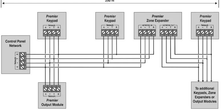
Keypads, zone expanders and output modules are all connected to the same network terminals located at the bottom left hand corner of the control panel and may be connected serially (daisy chain), in parallel (star) or any combination of the two (see Figure 1, page 11 for wiring details).
!"
A maximum of 2 zone expanders, 4 keypads and 1output module can be connected to the network. Whenever new devices are connected to the network, they must be confirmed onto the system using the ‘Confirm Devices’ menu option (see page 74 for details).
Wiring the Network
The networks are made up of four terminals incorporating power and data. To ensure correct operation, all four terminals on the device must be connected to the corresponding terminals on the control panel, or previous device (see Figure 1, page 11 for wiring details). The table below shows each terminal and its description:
Terminal Description
+ +12V Supply
- 0V Supply
T Transmit Data
R Receive Data
Devices can be connected using 4-core cable. However, it is recommended that 6 or 8-core cable is used as the spare cores can be used to ‘Double Up’ on the power connections if needed.
!"
Standard 7/0.2 alarm cable can be used for mostinstallations. However, under certain conditions it may be necessary to use screened cable.
Cable Distances
The maximum recommended distance for devices when using standard 7/0.2 alarm cable is:
• 250m for each branch when using the star (parallel) configuration
• When using a daisy chain (series) configuration the maximum distance will depend on the number of devices connected on the chain. The more devices that are connected, the shorter the distance to the last device (this is due to voltage drop in the cable)
Whichever method of wiring configuration is used, ensure that the voltage between the ‘+’ and ‘–’ terminals at each device is no lower than 10.0V when the system is running on the standby battery.
The table below shows maximum cable runs when one keypad or expander is installed using standard 7/0.2 alarm cable with various loads:
Configuration Max. Cable Run
1. Keypad + 2 PIR’s @15mA 250m
2. Expander + 2 PIR’s @15mA 250m
3. Expander + 8 PIR’s @15mA 100m
4. As No. 3 + 16Ω Speaker 30m
Distances of up to 1km can be achieved between the control panel and a device. However, a power supply must be installed close to the device to power it locally, this will help to overcome voltage drop caused by the long cable run.
Overcoming Voltage Drop
There are several ways to overcome voltage drop:
• Use thicker lower resistance cable. Standard 7/0.2 alarm cable has a resistance of 8Ω per 100m
• Double up on the power connections – this will require using a 6 or 8-core cable rather than a 4-core cable • Install a power supply to power the device locally,
remember to common the two negative connections
Installing a Power Supply
When a power supply is installed, the 0V connections on the power supply must be connected through to 0V on the control panel and the +12V connection between the control panel and the device must be disconnected (see Figure 2, on page 11 for wiring details).
Network Diagnostics
Each network has two LED’s to indicate data flow. The red LED indicates data flowing out of the ‘T’ terminal and the green LED indicates data flowing into the ‘R’ terminal. The table below shows each LED status and its meaning:
LED Status ‘T’ Wire OUT ‘T’ Wire IN
Red LED Flashing Normal Normal
Red LED On Panel Fault Cable Short
Red LED Off Panel Fault Panel Fault
LED Status ‘R’ Wire OUT ‘R’ Wire IN
Green LED Flashing Panel Fault Normal
Green LED On Panel Fault Cable Short
Green LED Off Normal No Data From Devices
!"
The LED’s are provided as an aid for fault finding andtherefore should not be completely relied upon to indicate that there is a fault.
Premier 24 Installation Manual Installation
Figure 1: Network Connections (250m without additional power supply).
Installation Premier 24 Installation Manual
Remote Keypads
The Premier LCD, LCDL, LCDP and LCDLP keypads all have: • 2 fully programmable zones
• 1 fully programmable –ve applied output • A fully programmable LED indicator (‘Info.’ LED) In addition the LCDL and LCDLP keypads have: • A fully adjustable speaker output
The LCDP and LCDLP keypads also have: • A built in Proximity Tag/Card reader The RKP8/16Plus keypads both have:
• Full LED Indication and 2 fully programmable zones
Keypad Layout
NETWORK Address Switch Output Network Terminals Tamper Switch Speaker Output Zones Piezo SounderConnecting Keypads
Keypads are connected to the network terminals located at the bottom left hand corner of the control panel (see pages 10 & 11 for connection details).
Keypad Addressing
Each keypad must be assigned a different address using the DIL switches located on the left hand side of the PCB. The table below shows the keypad addressing:
Address DIL 1 DIL 2 DIL 3 DIL 4
1 On or off Off Off Off 1234
2 Off On Off Off 1234
3 Off Off On Off 1234
4 Off Off Off On 1234
Engineers On On On On 1234
!"
Never set two keypads on the same network to thesame address.
When using a keypad as an Engineer’s keypad, the DIL switches must all be ‘On’.
Zone Numbering
The table below shows the zone allocation when the keypads are installed:
Address (Network 1) Zones (Network 2) Zones
1 Unmapped Unmapped 2 Unmapped Unmapped 3 Unmapped Unmapped 4 Unmapped Unmapped
!"
The zones inside the keypads are not seen by thesystem until they have been mapped to a zone number (see page 46 for details).
Keypad Zones
The keypad has two programmable zones (see page 17 for wiring details). Each zone is also fully programmable (see page 31 for programming details).
Keypad Output
The remote keypad has one programmable output, which can be used to drive auxiliary devices such as LED’s, sounders or relays etc. Wire as per Panel Outputs shown on page 19 (see page 48 for programming details). The electrical characteristics for the output are shown below:
Output Max Current Type
1 100mA Switched -ve
Keypad Speaker Output (
LCDL/LCDLP
Only)
The Premier LCDL and Premier LCDLP keypads have an output that can be used for driving up to one 16Ω or two 8Ω
loudspeakers (see page 18 for wiring details).
!"
The speaker volume is also fully adjustable (see page46 for details).
Programmable ‘Info.’ LED
The ‘Info.’ LED on the front of the keypad can be programmed to mimic the keypad output or show the armed status of alarm (see page 46 for details).
Adjustable Backlighting
To adjust the keypad backlighting press the YES key for 5 seconds, then with the YES key still pressed use
%
to increase or decrease the backlighting until the required brightness is achieved, then release both keys.!"
The backlight can only be adjusted when the keypadis not in a menu.
Keypad Lid Tamper
The lid tamper of each keypad can be disabled if required using the relevant keypad option in the Keypad Setup menu (see page 46 for details).
Premier 24 Installation Manual Installation
4XP
Zone Expander
This column is intentionally blank.
8XE
Zone Expander
The Premier 8XP Zone Expander has: • 8 fully programmable zones • Aux 12V Output
Expander Layout
Aux 12V (1 Amp) Zones 9-16 or Tampers 1-8 Connector for plugging on JP6 control panelConnecting Expanders
The 8XE local zone expander plugs directly on to the terminals located on the right hand side of the control panel (see below for details). To install the local zone expander proceed as follows:
1. Ensure that all power is removed from the control panel (mains and battery) before attempting to fit the expander. 2. Push the four support pillars (supplied) into the four
locating holes on the control panel PCB.
3. Align the local expander connector with the 8 way plug (JP6) on the control panel. Push expander into place, ensuring that all four pillars clip into the four locating holes on the local expander.
Zone Numbering
The table below shows the zone allocation when the expanders are installed:
Configuration Panel Zones Expander Zones
8XE = Zones 1 to 8 9 to 16
8XE= Tampers 1 to 8 Tampers 1 to 8
Expander Zones
The expander has eight programmable zones (see page 17 for wiring details). Each zone is also fully programmable (see page 31 for programming details).
Installation Premier 24 Installation Manual
8XP
Zone Expander
The Premier 8XP Zone Expander has: • 8 fully programmable zones
• 8 fully programmable –ve applied outputs • 1 programmable auxiliary input
• A fully adjustable speaker output
Expander Layout
1 2 3 OUTPUTS4 5 6 7 8 Enable Tamper 234 1 NETWORK IN + - T R + -NETWORK OUTT R Remote Power Aux 12vAmp1 Zones 5 & 6 Power LED Tamper Switch Engineers KeypadInterface TerminalsNetwork
Aux 12V Aux 12V Zones 7 & 8 Zones 1 & 2 Zones 3 & 4 Outputs 1 to 8 Speaker Output Aux Input Address Switch
Connecting Expanders
Expanders are connected to the network terminals located at the bottom left hand corner of the control panel (see pages 10 & 11 for connection details).
Expander Addressing
Each Expander must be assigned a different address using the DIL switches located in the centre of the PCB. The table below shows the expander addressing:
Address DIL 1 DIL 2 DIL 3 DIL 4
1 On or off Off Off Off 1234
2 Off On Off Off 1234
!"
Never set two expanders on the same network to thesame address.
Zone Numbering
The table below shows the zone allocation when the expanders are installed:
Address Zones
1 9 - 16
2 17 - 24
Expander Zones
The expander has eight programmable zones (see page 17 for wiring details). Each zone is also fully programmable (see page 31 for programming details).
!"
When using an 8XP Zone Expander, the wiringconfiguration must always be selected as ‘Double EOL’ even if wired as Double Pole.
Expander Auxiliary Input
The expander has one programmable input. This auxiliary input can be used to monitor auxiliary devices such as tamper loops etc. Wire as per Aux Tamper shown on page 18 (see page 48 for programming details). The system will respond as follows:
Input Status System Response
0V Applied Input Secure
0V Removed Input Active
!"
For further details on how the input status affects thesystem please refer to page 48.
Expander Outputs
The zone expander has eight programmable outputs, which can be used to drive auxiliary devices such as LED’s, sounders or relays etc. Wire as per Panel Outputs shown on page 19 (see page 48 for programming details). The electrical characteristics for the outputs are shown below:
Outputs Max Current Type
1 to 8 100mA Switched -ve
Expander Speaker Output
The expander has an output that can be used for driving up to one 16Ω or two 8Ω loudspeakers (see page 18 for wiring details).
Expander Lid Tamper
The lid tamper of each expander can be disabled if required by fitting a jumper link across the centre and right hand pins of the ‘Enable Tamper’ pins (JP2) leaving the left hand pin free. These pins are located to the left of the address DIL switch just beneath the fuse.
Premier 24 Installation Manual Installation
24
XID
Zone Expander
One 24XID expander can be connected to the Premier 24 to provide 1 ID loop supporting up to 24 biscuits.
Installation
Before connecting the 24XID expander module, isolate ALL power from the control panel (AC mains and battery), do not continue if there is still power present on the control panel. 1. Plug the expander onto the control panel, see 24XID
installation manual for details.
2. Connect the iD devices to the expander module, see “iD Connections”.
3. Reapply power to the control panel and program the necessary options on the panel see 24XID installation manual for details.
iD Connections
Each iD biscuit is connected across a two-wire detector loop. Apart from observing the correct polarity, any wiring configuration can be used, as shown in the diagram below:
XID Zone Expander LOOP 1 + -09 10 11 12 13 03 04 05 06 01 02 08 07 14
Cabling Considerations
The iD loop can be wired using standard 4-core alarm cable, this allows 2 cores to be used for the iD biscuit and 2 cores for supplying 12V power for PIR's etc.
The number of biscuits that can be connected per cable run is determined by the impedance of the cable used. Standard 4-core alarm cable (7/0.2mm) has a resistance of approximately 8 Ohms per 100 metres. The following table shows the maximum number of biscuits that can be connected at the end of a single cable run using standard 4-core alarm cable:
Cable Length Maximum Number of Biscuits
100m 30 200m 15 400m 7 800m 3
If a different type of cable is used, the distances should be re-calculated. e.g., if 7/0.4mm cable is used, a single run of 200m would support 30 devices on the end as the resistance of the cable is halved.
When installing the iD loop it is usually more practical to run several cables from the expander module to the different areas of protection. This effectively reduces any distance problems and makes fault finding much easier.
To reduce the risk of induced interference and wherever possible, cables should not be positioned along side mains power, telephone or other data transmission cables, or run within the same ducting or trunking as any other cables. The wiring for the system’s internal sounders (loudspeakers) should not be connected in the same multi-core as the iD loop.
Biscuit Connections
Each iD biscuit is identified by its own number 01 to 30 and contains its own internal sensor that is continuously monitored by the expander module. The diagram below shows the connections to the biscuit for monitoring both tamper and alarm contacts.
iD Biscuit
Alarm
Tamper
LOOP +
LOOP
-White Yellow Blue Biscuit iD 01When the tamper switch is opened, the iD biscuit is taken offline and a tamper condition is generated by the control panel. If the alarm switch is opened the biscuit's internal sensor changes state and the control panel will see this as an active condition and will respond as appropriate.
The diagram below shows the typical wiring of a biscuit to a standard PIR.
+12V
ALARM TAMPER
From Expander To next detector
Red Black Blue Yellow Red Black Blue Yellow
White Blue Yellow
0V
Installation Premier 24 Installation Manual
OP16
Output Expander
A maximum of 1 output module can be connected to the network along with keypads and zone expanders.
The Premier OP16 output module can be set up to mimic the outputs of zone expanders.
!"
In order for an output module to mimic zoneexpander outputs, the output module must be addressed the same as the zone expander that it is mimicking.
Output Module Layout
Power LED Tamper Switch Network Terminals Aux 12V and Tamper Output NETWORK IN + - T R + -NETWORK OUTT R Power 1A m p A ux 1 2v 1 Amp 234 1 BANK 1 Remote Bank 2 Outputs 1 to 8 1 2 3 4 5 6 7 8 BANK 2 1 2 3 4 5 6 7 8 BANK 1 Bank 1 Outputs 1 to 8 Tmp-Aux 12V + + -234 1 BANK 2 Network Terminals Engineers Keypad Interface
Connecting Output Modules
Output modules are connected to the network terminals located at the bottom left hand corner of the control panel (see pages 10 & 11 for connection details).
Output Module Addressing
Each output module must be assigned a different address using the DIL switches located in the centre of the PCB.
!"
Bank 1 switch sets the address of the device thatBank 1 outputs 1 to 8 will mimic.
!"
Bank 2 switch sets the address of the device thatBank 2 outputs 1 to 8 will mimic.
The table below shows the output module addressing: Address DIL 1 DIL 2 DIL 3 DIL 4
1 On or off Off Off Off 1234
2 Off On Off Off 1234
Output Module Numbering
The table below shows the output allocation when the output modules are installed:
Address Outputs
1 Expander 1, 1 - 8
2 Expander 2, 1 - 8
Outputs
The output module has 16 programmable outputs, which can be used to drive auxiliary devices such as LED’s, sounders or relays etc. Wire as per Panel Outputs shown on page 19 (see page 48 for programming details). The electrical characteristics for the outputs are shown below:
Bank Outputs Max Current Type
1 1 to 8 100mA Switched -ve
2 1 to 8 100mA Switched -ve
Tamper Output
The tamper switch on the output module is connected to the tamper output at the top of the module. If monitoring of the lid tamper is required, this output must be connected to a suitable input on the control panel or zone expander.
Premier 24 Installation Manual Installation
Zone Connections
The Premier 24 has 8 zones on board the control panel that can be wired as either ‘Single Pole’ or ‘End Of Line’.
!"
Any zones that are not being used must be linked outor programmed as ‘Not Used’ (see page 31 for details).
Single Pole
Use this wiring configuration when connecting normally closed or normally open detection devices to the zone using 2-Wires.
!"
When using this configuration the tampers must bewired to the Aux tamper input (see page 18 for details).
Double Pole
Use this wiring configuration when connecting normally closed or normally open detection devices to the zone using 4-Wires.
!"
When using this configuration, no more than 10detectors can be connected to each zone.
When wiring device as normally open contacts as above, ensure that system Config. option 21 is set to ‘Zone Short = Active’ (see page 41 for details). When wiring double pole (4-wires) to a keypad or zone expander, the wiring configuration must always be programmed as ‘Double EOL’.
End Of Line
Use this wiring configuration when connecting normally closed or normally open detection devices to the zone using 2-Wires.
When Configuration Option 21 (see page 41 for details) is programmed as ‘Short = Tamper’ the system will respond as follows:
Zone Status System Response
0 - 2k Zone Tamper
2k1 - 4k6 (EOL) Zone Secure
4k7 - 20k Zone Active
21k+ Zone Tamper
!"
When using this configuration, no more than 3detectors can be connected to each zone.
When Configuration Option 21 (see page 41 for details) is programmed as ‘Short = Active’ the system will respond as follows:
Zone Status System Response
0 - 2k Zone Active
2k1 - 4k6 (EOL) Zone Secure
4k7 - 30k Zone Active
31k+ Zone Tamper
!"
When using this configuration, no more than 5detectors can be connected to each zone.
Installation Premier 24 Installation Manual
Auxiliary Tamper Connections
The Auxiliary Tamper terminals allow the control panel to monitor the tamper loops of external devices such as power supplies etc.
!"
If the ‘Auxiliary Tamper’ terminals are not being usedthey must be linked out.
Speaker Connections
This output can be used for driving up to one 16Ω or two 8Ω
loudspeakers as shown below:
Tamp
Strb 0V Bell+12V PG 1 SPK
-Tamp
Strb 0V Bell+12V PG 1 SPK
-!"
For details on testing Speaker outputs, see page 73External Sounder Connections
The following terminals have been provided for connection to an external sounder:
(A)+12V
12V supply (protected by a 900mA PTC – F2). Normally connected to ‘+12V’ on the sounder.
(B) Bell –
Sounder output, switches to 0V in alarm (SAB) and is rated at 500mA. Normally connected to Trigger -ve on the sounder. This output can also be programmed for SCB operation (see page 40 for details).
(C) Tamp
Negative tamper return. Normally connected to ‘Tamper Out’ on the sounder. If this terminal is not being used, it ust be connected to ‘0V’.
(D) 0V
0V supply. Normally connected to ‘0V’ on the sounder. (S) Strb –
Strobe output, switches to 0V in alarm and is rated at 500mA. Normally connected to strobe -ve on the sounder (where applicable, connect the strobe +ve to +12V).
Texecom External
Sounder
Control
Panel
+12V (A) 0V (D) Tamper (C) Strobe -ve (S) Trigger -ve (B)!"
For details on testing the ‘Bell’ outputs, see page 73When an Engineers code is entered to gain access to the programming menu, the Strobe output will pulse 3 times, invoking Engineers Hold Off mode if a Texecom bell box is connected.
Premier 24 Installation Manual Installation
Panel Outputs 1 - 6 and PG1
The control panel has 8 programmable outputs, which can be used to drive auxiliary devices such as LED’s, sounders or relays etc. (see page 50 for programming details). The table below shows the electrical characteristics for each output:
Terminal Max Current Operation
1 100mA Switched 0V 2 100mA Switched 0V 3 100mA Switched 0V 4 100mA Switched 0V 5 100mA Switched 0V 6 100mA Switched 0V PG1 100mA Switched 0V
L/M N/A 0V removed = Line Fault
R/R N/A 0V applied to reset
DC+ N/A +12V Power (unfused)
DC- N/A 0V Power
Wiring Outputs
The diagram below shows some typical wiring examples:
!"
For details on testing outputs, see page 73.
Wiring a Stand Alone Communicator
The diagram below shows a typical wiring example:Control
Panel
Power 1 3 4 5 6 7 8 12V 0VStand Alone
Communicator
C DC + L/M R/R DC -1 3 4 5 6 Channel Inputs Programmed as PositiveRemoved FaultLine
Panel Outputs
Installation Premier 24 Installation Manual
Plug-on Digimodems
The Com300 is a multi format 8-channel digital
communicator/300-baud modem for use with a standard analogue telephone line.
The Com2400 is a multi format 8-channel digital communicator/2400-baud modem for use with a standard analogue telephone line in addition, this modem can also send Short Message Service (SMS) text messages to a mobile phone.
The ComISDN is a multi format 8-channel digital communicator/modem for use with an ISDN telephone line. These Digimodem can be used to report system events to an Alarm Receiving Centre using Fast Format, Contact ID or SIA Level II or to upload/download control panel information using the Wintex UDL software and a PC.
Plugging on the Digimodem
Ensure that the board is the correct way up (see below). Locate the eight-pin plug into the digimodem socket on the control panel and line up the mounting holes with the pillars in the base. Once all the holes line up, press down gently until the pillars snap into the holes.
Com2
JP6
Standard Telephone Line Connections
A standard telephone line must be connected to the
Com300 or Com2400 digimodem as shown below:
R1 R T T1 To other telephone extension sockets Com300 Com2400or Master Socket T = 5 or A - White/Blue ring R = 2 or B - Blue/White ring 3 2 1 6 5 4 Telephone cable Type 1/0.5mm CW1308 This terminal must be connected to the incoming AC Mains earth supply
ISDN Telephone Line Connections
An ISDN telephone line must be connected to the ComISDN
digimodem as shown below:
ComISDN
ISDN Terminal
RJ45 Lead
Premier 24 Installation Manual Installation
RP9 Radio-Pad
Before connecting the Radio-Pad, isolate ALL power from the control panel (AC mains and battery), do not continue if there is still power present on the control panel.
To install the Radio-Pad onto the control panel:
• Connect the 7-Way connector of the RPD-Com lead to Com2 on the control panel
• Connect the 25-Way D-Type connector of the RPD-Com to the Radio-Pad
• Locate the power lead connector into the socket at the bottom of the Radio-Pad
• Connect the Black lead to the DC- terminal on the control panel
• Connect the lead with the White stripe to the DC+ terminal on the control panel
• Follow the procedure for Registering the Radio-Pad
Registering the Radio-Pad
Whenever a Paknet Radio-Pad is installed or moved, it must be registered onto the network. To do this:
• Press and hold the test button on the front of the Paknet Radio-Pad
• With the test button still pressed, connect power to the control panel and wait for the yellow service light on the Radio-Pad to flash
• Release the test button
Within 2 minutes the yellow service light should stop flashing and remain steady. This means that the Paknet Radio-Pad has now selected and locked on to the Base Station with the strongest signal.
The Paknet Radio-Pad should be re-registered on every site visit, this is to ensure that any new Vodafone Packet Radio Service Base Stations in the vicinity are recorded by the Paknet Radio-Pad.
Programming the
Radio-Pad
• Program Com 2 for Radio-Pad operation (see page 61 for details)
• Refer to the Radio-Pad installation guide for full programming details.
GSM Module
Before connecting the GSM Module, isolate ALL power from the control panel (AC mains and battery), do not continue if there is still power present on the control panel. To install the GSM Module onto the control panel:
• Connect the 7-Way connector of the GSM-Com lead to Com2 on the control panel
• Connect the RJ45 connector of the GSM-Com to the GSM Module
• Locate the power Jack Plug into the socket at the bottom of the GSM Module
• Insert a SIM card into the bottom of the GSM Module
• Connect power to the control panel
Programming the
GSM Module
• Program Com 2 for GSM Module operation (see page 61 for details)
• Refer to the GSM Module installation guide for full programming details.
PC-Com
The PC-Com has two connectors. The 9-way D-type connector is for connection to a serial port on a computer and the 5-way Molex connector plugs onto Com 1 on the control panel.
UNI-Com
The UNI-Com has two connectors. The 9-way D-type connector connects to any supported serial device, the 5-way Molex connector plugs onto Com 1 on the control panel.
PRINT-Com
The PRINT-Com has two connectors. The 25-way D-type connector connects to a Serial Printer and the 5-way Molex connector plugs onto Com 1 on the control panel.
Commissioning and Troubleshooting Premier 24 Installation Manual
GSM-Com
The GSM-Com has four connectors. The RJ45 connector connects to the GSM Module, the 7-way Molex connector plugs onto Com 2 on the control panel, the 5-way Molex connector plugs onto the Audio connector on a Com300 or Com2400 and the jack plug connects to the power connector on the GSM Module to provide power (5V).
NET-Com
The NET-Com has two connectors. The RJ45 connector connects to a TCP/IP network and the 5-way Molex connector plugs onto Com 1 on the control panel.
Comms
Connecting a Computer
The Premier 24 supports local uploading and downloading between the control panel and a PC running Wintex UDL
software. Uploading and Downloading can be used to program and interrogate the control panel.
In order for the computer to work correctly, ensure that it is set to the following:
• UDL Password (see page 60 for details)
!"
In order to upload and download to the controlpanel locally, a PC-Com lead is required.
PC-Com Aux 12V +B att A.C.
BatteryBellNetwork F5F2F3F4 En gineer Remote C om2 J P6 C om1 Load De f aul ts Tx2 Rx 2 Tamp Strb 0VBell+12V P g 1S p k -+-A u x1 2 VAu x Ta m p
Connecting a Printer
The Premier 24 supports printer facilities. The printer is connected to the Com 1 connector located on the control panel and can be used to print the control panel event log. In order for the printer to work correctly, ensure that it is set to the following:
• Baud Rate = 4800 • Parity = None • Start Bits = 1 • Stop Bits = 2 • Data Bits = 8 • DTR = Normal
• Columns = 40 or 80 (see page 40)
!"
In order to connect a printer to the control panel, aPRINT-Com lead is also required.
DATAC or RS232 printer RS232 Data
Connect to COM1
Premier 24 Installation Manual Installation
3. Commissioning and Troubleshooting
Commissioning
Once ALL connections have been made to the control panel and power is ready to be applied, you should read this section before continuing.
When applying power for the first time, the factory default settings must be loaded. The default settings ensure that the control panel software is reset and all programming information is loaded into memory. For a complete list of factory default settings, see page 26 The factory default settings are loaded by applying power to the control panel whilst at the same time, holding down the Factory Default button.
To default the control panel, proceed as follows:
• Connect the black battery lead to the negative (–) terminal of the standby battery and the red battery lead to the positive (+) terminal of the standby battery • Press and hold the Factory Default button
• Press the battery kick-start button to connect the battery and ensure that the green power light illuminates
• After the power light has illuminated, let go of the Factory Default button (the power light will continue to flash whilst the factory default settings are being loaded, this can take up to 30 seconds)
• If the system goes into alarm, enter the default Engineer code
!"#$
, and the alarm tone will stop• To access the Engineer Programming Menu, enter the default Engineer code
!"#$
• Program the system as described in section 6 (Programming the Control Panel)
• Perform a zone test as described on page 73. Remember that some powered detectors (e.g. PIR’s and combined technology detectors) take several minutes to warm up and become operational
• Test the internal sounder, external sounder and strobe as described on page 73
• Replace the lid and secure with the lid screw supplied • Press
&
followed by YES to leave theprogramming menu, the system will return to normal • The display will be showing that there is a ‘Mains Power
Off’ condition. Switch on the AC mains supply to the control panel
• The normal banner message (if programmed) will now be displayed
Installation is now complete and the system is ready for use.
Trouble-Shooting
Control Panel
No Power to unit (mains only)
• Check the mains block fuse and replace if blown
• Check for loose wires at the mains block, the transformer and the AC terminals on the PCB
• Check the mains block is connected correctly; live to live (brown), neutral to neutral (blue)
No Power to unit (battery only)
• Don’t forget to press the battery kick-start button • Check the battery PTC LED for faults
• Check for loose wires at the BATT terminals on the PCB • Check that the battery wires are connected correctly;
red from BATT+ to the battery positive (+), black from BATT- to the battery negative (-)
Network Data LED’s are not flashing
• Remove ALL power (AC Mains and Battery) and remove ALL wires from the network terminals. Then re-apply power again before referring to the Network Diagnostics table on page 10
External Sounder not Functioning (No 12V Output)
• Ensure that JP9 is fitted, as without this jumper link there will be no 12V power from the 12V Bell Terminals.
Keypads
Keypad does not operate
• Check that the keypad is wired correctly from the control panel (see page 10 for wiring details)
• Check the network PTC LED for faults
• Use the network diagnostics (see page 10 for details)
Keypad does not accept codes
• If the system has more than one keypad check that each keypad is addressed differently, see page 12 for details • If the keypad is on a long cable run, check the voltage
between the ‘+’ and ‘–’ terminals at the keypad and ensure that it measures no less than 10.0V
• Check that you are using the correct User codes. The default Engineer code is
!"#$
and the default Master User code is'()*+
• Check that the User code you are using is not ‘Locked’,if the User code is locked then the access code will only be accepted when the PGM is off (see page 42 for details)
Commissioning and Troubleshooting Premier 24 Installation Manual
Keypad zones do not operate
• Each keypad zone has to be mapped onto the system before it can be used (see page 46 for details)
• The zone is not programmed (see page 31 for details)
Keypad emergency keys do not operate
• Each keypad can be configured so that the emergency keys PA, FIRE and MEDICAL can be enabled or disabled. Check that the keypad has been programmed correctly (see page 46 for details)
Expander
Expander does not operate at all
• Check that the expander is wired correctly from the control panel (see page 10 for wiring details)
• Check the network PTC LED for faults
System does not recognise zones
• If the expander is on a long cable run, check the voltage between the + and – terminals at the expander and ensure that it measures no less than 10.0V
The speaker output does not work
• The expander can be configured so that Alarm, Entry, Exit, Chime tones etc. can be enabled or disabled. Check that the expander has been programmed correctly (see page 48 for details)
• The speaker volume on the expander is electronically adjustable. Check the volume is set to the desired level (see page 48 for details)
Zones
One or more zones show an alarm
• Check that the zone is wired correctly (see page 17 for wiring details)
Digimodem
The Digimodem will not dial
• By default the communicator is disabled, check that the communicator is enabled (see page 58 for details) • Check that the telephone line has been correctly wired
to the communicator (see page 20 for wiring details) • Check that the telephone numbers are programmed
correctly (see page 57 for details)
• Check that the account numbers are programmed correctly (see page 57 for details)
• Check that the dial attempts are not programmed as zero (see page 57 for details)
• Check that the reporting options have been programmed correctly (see page 57 for details)
Digimodem dials but does not communicate
• Check that the telephone numbers are programmed correctly (see page 57 for details)
• Check that the correct protocol is programmed (see page 57 for details)
Operation
The system will not allow me to arm
• Check that there are no outstanding problems (see page 25 for details)
• Check that there are no outstanding alarms that require resetting (see page 25 for details)
• Check that the User code has been programmed to allow arming (see page 69 for details)
The system will not allow me to disarm
• Check that the User code has been programmed to allow disarming (see page 69 for details)
Premier 24 Installation Manual Commissioning and Troubleshooting
Reset and Service Messages
When the system requires attention because of a potential problem, the display will show one of three service messages. These messages can also be accessed at any time, allowing the user to view installer information.
!"
These messages would normally be programmedwith the telephone numbers of the installer or the Alarm Receiving Centre (see page 43 for details). To display the service messages, proceed as follows: The display will normally show the time and date:
!!!!
!"#$!%&!'()!*%%+
Press
,
followed by!
for the Service message:,(--!.-()/!,01 !!20)!3$)456$
Press
,
followed by"
for the Reset message:,(--!78958$$)!:0 !!;$<$:!3=<:$/
Press
,
followed by#
for the Anti-code message:,(--!.;,!:0 ;$<$:!3=<:$/
Press
-
to exit from the message, the display will then return to normal.When alarm information is being displayed, pressing the SCROLL key will slow down the display and also allow manual scrolling through the events.
Fault Warning Tones
When a fault condition occurs i.e. mains fail, line fault etc. the internal sounders will chime every 30 seconds for 3 minutes. The chiming will automatically stop when a valid User code is entered, when
-
is pressed or after 3 minutes (whichever occurs first). The fault indication will only be cleared from the display when the fault has been rectified i.e. power, telephone line has been restored.Other Messages
.-()/!78958$$) >0)?589!@8!35:$
The alarm engineer has logged into the programming menu and is working on site (this message will clear when the engineer logs off or the system is armed).
,08A5)/!B$456$< !"#$!%&!'()!*%%+
The number of devices connected to the networks has changed from the last time a ‘Confirm Devices’ was done.
;$/0:$!C$=D(E!5< 80F!G@,C7B!0#:
To many invalid code attempts have caused the keypad to lock out. The keypad will remain like this for 5 minutes.
H0#!8$$E!(!#<$) :0!$8(I-$!(66$<<
Engineer access has been programmed for Engineer code + User code (see page 40 for details).
Fault Messages
3$)456$!;$J#5)$E !"#$!%&!'()!*%%+
The service timer has expired indicating that the system requires a service, zones that have been placed on test have failed the test or a fault has occurred that requires attention (the system can normally still be used). Contact your alarm company to advise.
'(58<!K0F$)!@AA !"#$!%&!'()!*%%+
There is a Mains failure (the keypad may chime every minute, enter a valid code to stop the chime). The display will automatically clear when mains is reapplied.
KL08$!G58$!2(#-: !"#$!%&!'()!*%%+
There is a Phone Line fault (the keypad may chime every minute, enter a valid code to stop the chime). The display will automatically clear when line fault clears.
!M!N@!O.""7;H!M !"#$!%&!'()!*%%+
The Standby Battery has not been connected, the display will automatically clear after 1 minute.
O(::$)=!2(#-: !"#$!%&!'()!*%%+
There is a fault with the control panel standby battery.
K(8$-!G5E!"(/D$) !"#$!%&!'()!*%%+
There is a fault with the control panel lid tamper.
O$--!"(/D$) !"#$!%&!'()!*%%+
There is a fault with the bell tamper on the control panel.
.#P5-5()=!"(/D$) !"#$!%&!'()!*%%+
There is a fault with the auxiliary tamper on the control panel.
O$--!2#<$!O-0F8 !"#$!%&!'()!*%%+
The bell/Strobe PTC has failed
.#P1!2#<$!O-0F8 !"#$!%&!'()!*%%+
The 12V Auxiliary PTC has failed
;CK!Q!"(/D$) !"#$!%&!'()!*%%+
There is a fault with the lid tamper of Keypad X.
;CK!Q!G0<: !"#$!%&!'()!*%%+
Keypad X has been lost off of the system.
7QK!Q!"(/D$) !"#$!%&!'()!*%%+
There is a fault with the lid tamper of Expander X
7QK!Q!G0<: !"#$!%&!'()!*%%+
Expander X has been lost off of the system.
7QK!Q!G0!R0-:< !"#$!%&!'()!*%%+
The voltage at expander X is very low.
7QK!O$--!"(/D!Q !"#$!%&!'()!*%%+
The expander’s Bell input (that is programmed as bell tamper) is in fault.
7QK!.#P!"(/D!Q !"#$!%&!'()!*%%+
The expander’s Auxiliary input (that is programmed as aux tamper) is in fault.
Factory Defaults Premier 24 Installation Manual
4. Factory Defaults
Menu Option Default
User Codes
Setup Users User 00 (Engineer) 1234
User 01 (Master) 5678
User 02 - 25 Not Defined
1. Zone Setup
Zones Types 1 Entry/Exit 1
2 Guard Access
3 - 8 Guard
All Other Zones Not Used
Zone Text All Zones Not Defined
Zone Chime All Zones Silent
2. Arming Options
Timers Exit Delay 030 Seconds Entry Delay 1 015 Seconds Entry Delay 2 030 Seconds 2nd Entry Dly 000 Seconds
Bell Delay" 000 Minutes Bell Duration 015 Minutes Coms Delay 000 Seconds Part Bell Dly 000 Seconds Arming Modes Full Arm" Entry/Exit Part Arm 1" Instant Part Arm 2" Instant Part Arm 3" Instant Options 1: Auto Part Arm" Disabled
2: Part Arm Silent" Disabled 3: Remote Arm/Disarm Enabled 4: Time Arm CT1" Disabled 5: Alarm Eng Reset" Disabled 6: Confirmation Reset" Enabled 7: Tamper Eng Reset" Enabled 8: Anti-code Reset" Enabled 9: Arm With L/Fault" Enabled 10: Arm With AC Fail Enabled 11: Part Arm Coms" Disabled 12: Unarm Fire Coms" Disabled 13: Unarm Tamper Coms" Disabled 14: Log Part Omits" Disabled 15: Confirm In Entry" Disabled 16: Conf. After Entry" Disabled
Menu Option Default
3. Global Options
System Timers 1: Exit Settle Time 008 Seconds 2: Double Knock Dly 030 Seconds 4: Activity Delay 024 Hours 5: Abort Delay 180 Seconds 6: Courtesy Time 060 Seconds 7: Pulse Period 1 010 Seconds 8: Line Fault Delay 030 Minutes 9: AC Off Delay 030 Minutes 10: Batt Test Period 024 Hours 11: Batt Test Time 060 Seconds 12: Soak Test Time 014 Days 13: Service Interval 000 Weeks 14: Test Call Every 000 Hours
15: Zone Response 075x10mSec.
16: Confirmation Dly 045 Minutes System Config. 00: Bell on Arm Fail No Bell
01: Bell is an SCB SAB 02: Manual BST/GMT Auto 03: Leave Omits Remove 04: Enforce Com Delay Overide 05: NVM is Locked Unlocked 06: Eng. + User Code Engineer Only 07: Omit Tampers YES NO
08: 40 Column Printer 80 09: View Act. Fault Hide 10: View Zone Faults Hide 11: Code Tampers Enable 12: Code Tamp Locks Alarms 13: Zone Short Active Tamper
14: R/R=Silence/RST Reset Only 15: Test Call = CT3 Timed
16: Batt Test = Disarm Timed 17: Bell = 2nd Alarm 1st Alarm 18: SNDR = 2nd Alarm 1st Alarm 19: Abort = User Reset Eng. 20: 8XE = Tamper 1-8 Zones 9-16 21: 1st Zone = Confirm 2nd Zone 22: Access = Confirm No Conf. 23: EN50131 Enabled Disabled System Options 1: Advisory Volume 5
2: Chime Volume 3 3: No. of Re-Arms 3 4: Anti-code Resets 3 Control Timers 1 - 4 Not Defined System Text Reset Message Call Engineer to
Reset System Anti-code Message Call ARC Centre
to Reset System Service Message Call Alarm Co.
For Service Location Text No Location Text
Has Been Setup Banner Message Not Defined Part Armed Banner * PART ARMED * Printer Header Printer Header Part Arm 1 Evening Arm Part Arm 2 Bedtime Arm 1 Part Arm 3 Bedtime Arm 2 Speaker Tones All Tones Enabled