BackFi: High Throughput WiFi Backscatter
Dinesh Bharadia
†, Kiran Joshi
†, Manikanta Kotaru, Sachin Katti
Stanford University
{dineshb, krjoshi, mkotaru, skatti}@stanford.edu
†co-primary authors
ABSTRACT
We present BackFi, a novel communication system that en-ables high throughput, long range communication between very low power backscatter IoT sensors and WiFi APs using ambient WiFi transmissions as the excitation signal. Specif-ically, we show that it is possible to design IoT sensors and WiFi APs such that the WiFi AP in the process of trans-mitting data to normal WiFi clients can decode backscatter signals which the IoT sensors generate by modulating in-formation on to the ambient WiFi transmission. We show via prototypes and experiments that it is possible to achieve communication rates of up to 5 Mbps at a range of 1 m and 1 Mbps at a range of 5 meters. Such performance is an or-der to three oror-ders of magnitude better than the best known prior WiFi backscatter system [27, 25]. BackFi design is en-ergy efficient, as it relies on backscattering alone and needs insignificant power, hence the energy consumed per bit is small.
CCS Concepts
•Information systems → Sensor networks; •Hardware →Digital signal processing;Sensors and actuators; Wire-less integrated network sensors;
Keywords: Full Duplex Backscatter; Backscatter Commu-nication; Internet of Things (IoT); WiFi Backscatter; Backscat-ter Decoder; Ambient BackscatBackscat-ter
1.
INTRODUCTION
Embedded and connected gadgets - colloquially referred to as the Internet-of-things (IoT) - are increasingly making it possible to continuously monitor our bodies, personal lives and surroundings to improve health, energy usage, security and so on. These gadgets (e.g. wearable, fitness/health track-ers, security cameras/microphones, thermostats [35]) inte-grate with cheaply available sensing technology to continu-ously measure physical variables such as temperature, heart rate, ambient sounds, etc. and upload them via wireless links Permission to make digital or hard copies of all or part of this work for personal or classroom use is granted without fee provided that copies are not made or distributed for profit or commercial advantage and that copies bear this notice and the full citation on the first page. Copyrights for components of this work owned by others than the author(s) must be honored. Abstracting with credit is permitted. To copy otherwise, or republish, to post on servers or to redistribute to lists, requires prior specific permission and/or a fee. Request permissions from [email protected].
SIGCOMM ’15, August 17 - 21, 2015, London, United Kingdom
c
2015 Copyright held by the owner/author(s). Publication rights licensed to ACM. ISBN 978-1-4503-3542-3/15/08. . . $15.00
DOI:http://dx.doi.org/10.1145/2785956.2787490
to the cloud. Analytics applications then analyze such data to implement useful functionality such as fitness monitoring, intruder detection, regulating HVAC, etc. The future is likely to bring many more such devices helping us instrument more parts of our lives and surroundings, and enable us to measure and analyze almost every aspect of our lives.
We will refer to these IoT gadgets as either IoT sensors, or tags, or simply sensors in the remaining of our paper de-pending on the context. To widely realize the IoT vision, we believe that the wireless connectivity on these devices needs to satisfy three key requirements:
• R1: Sufficient throughput & range: A typical such gad-get produces anywhere between a few Kbps (e.g. tempera-ture sensors measuring every 100 ms) to a few Mbps (e.g., security microphones/cameras recording audio/video), and can be placed anywhere in the home or on the body. So the wireless link from the gadget to the wired gateway con-nected to the Internet should provide at least afew Mbps of uplink throughput and 1-5 meters of range.
• R2: Very low power design: These gadgets need to be able to operate for a long time without requiring battery replacements, or ideally without batteries at all. Recent work has demonstrated the possibility of powering these devices primarily using power harvesting from ambient RF sources such as TV and cellular signals. A typical RF powered device can harvest upto 100 microwatts of power [51, 44, 29] from TV signals. Hence, ideally the gadget’s radio should provide the necessary throughput and range
using a few tens of microwatts of power to be operable
without batteries. If feasible this would eliminate the need for dedicated powering infrastructure such as RFID read-ers.
• R3: Reuse ambient signals: Ideally the IoT sensors should be able to piggyback their data on ambient, widely preva-lent communication signals such as WiFi, Bluetooth etc. For example, while a WiFi AP is transmitting a packet to a standard WiFi client, an IoT sensor should be able to modulate its own information on the ambient WiFi signal and communicate its own data back to the AP. However this should not interfere with the normal WiFi communi-cation from the AP to the client. If such a capability is feasible, then one can imagine being able to provide con-nectivity to IoT sensors using infrastructure that is already being widely deployed for standard wireless communica-tion, thus reducing complexity and cost.
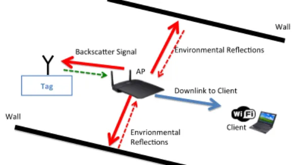
Envrionmental, Reflec0ons, Backsca4er,Signal, Wall, Wall, Downlink,to,Client, Tag$ Environmental,Reflec0ons, AP, Client,
Figure 1:Overview of BackFi backscatter system : The AP trans-mits packet that is meant for the WiFi client (in blue), the transmit-ted signal (in red) is also reflectransmit-ted by reflectors in the environments like walls. The IoT sensor also receives these transmissions, and modulates its data on it and backscatters the signal to the AP (in green).
To the best of our knowledge, no current systems satis-fies all three requirements. Recent work on WiFi backscat-ter [27, 25] is the closest, but it does not satisfyR1, it only provides around0.5Kbps of uplink-throughput and a range of1meter which is insufficient for many applications. RFID-based systems satisfyR1[55, 19, 49] and some of them
sat-isfy R2, but not R3. They would require the widespread
deployment of dedicated RFID reader infrastructure as well as require their own spectrum band of operation in the unli-censed band. Standard communication radios such as WiFi or Blue-tooth Low Power would satisfyR1andR3, but clearly
cannot satisfyR2, they require between30−50mW
(Blue-tooth) to several hundred mW (WiFi) of power to operate. Our goal is to design a radio uplink for IoT sensors that satisfies all the above requirements. We present BackFi, a novel communication link design between backscatter IoT sensors and WiFi radios. The key contributions are a IoT sensor design for backscattering WiFi signals, and a novel radio circuit and algorithm design at the WiFi AP which dou-bles up as the (AP) reader decoding the backscatter signals from the IoT sensor. The AP reader operates while it is send-ing a standard WiFi packet to a standard WiFi client as seen in Fig. 1. The design satisfies the throughput and range re-quirements described above, it delivers at least 1 Mbps of
throughput even at a range of5m and much higher
through-puts upto6.67 Mbps at shorter ranges of a meter, To put
these performance numbers in context, they are between one to three orders of magnitude better than the best known WiFi backscatter system [27, 25].
BackFi’s design makes three key technical contributions:
• First, we design a novel low power IoT sensor that can
backscatter standard WiFi signals while being able to sus-tain high data rates of around5Mbps. The IoT sensor con-sists of a low power design for phase modulations ranging from BPSK to 16-PSK as well as mechanism for detect-ing WiFi transmission on which IoT sensor data can be modulated and backscattered.
• Second, a novel design of the WiFi AP radio such that it
can receive the backscatter signals even while it is simul-taneously transmitting a WiFi packet to a standard WiFi client. We leverage recent work on self-interference
can-celation for full-duplex radios to enable the backscatter signal to be received while the WiFi device is transmit-ting [17, 20, 43, 12, 8, 11, 9, 8, 26, 16, 39, 10]. Specifi-cally, the backscatter signal is a modulated version of the transmitted signal itself. Hence self-interference cance-lation has to be modified to ensure that the backscatter signal itself does not get canceled. We design novel self-interference estimation techniques that protect the backscat-ter signal from any degradation due to cancelation.
• Third, we invent novel demodulation and decoding
algo-rithms that can estimate fine-grained changes in the backscat-ter signal to decode the IoT sensor data. Specifically, we show that WiFi backscatter can be modeled as a chan-nel that is linear but time-varying modifying the IoT sen-sor data. BackFi incorporates novel decoding algorithms that can continuously track the time-varying channel and use standard diversity combining techniques such as Max-imal Ratio Combining (MRC) to deliver a reliable, high throughput link [13].
We prototype BackFi and show that it can provide 5 Mbps of throughput at 1 m range and at least 1 Mbps at 5 m range. In comparison the best performing prior WiFi backscatter system [27, 25] provides a throughput of up to 1 Kbps, a range of less than a meter. We also show that BackFi has minimal impact on the operation of the standard WiFi net-work whose ambient signals it is piggybacking on to backscat-ter its own data.
We also note that the focus of this paper is on the uplink from the IoT sensor to the BackFi AP. The reason is that the IoT applications that we are designing for are bottle-necked on the uplink. These gadgets (such as fitness trackers, home sensors, wearables, etc) are collecting a lot of sensor data and need to upload them to the cloud and downlink often isn’t needed, or if it is, very low throughput of a few Kbps suffice [35, 53]. Hence in the rest of the paper we will focus on the uplink, but note that prior work has already demon-strated WiFi backscatter designs (which can be used with
BackFi too) for the downlink that can provide upto20Kbps
[27]. We further note that although we have chosen WiFi signaling for the description and implementation of BackFi, the system is applicable for other types of communication signals like Bluetooth, Zigbee, etc., as well.
2.
RELATED WORK
BackFi is most closely related to recent work on WiFi backscatter [27, 25]. The prior design also uses ambient WiFi transmissions to backscatter data. Specifically, IoT sensors encode data in binary decisions of whether or not to backscatter the received packet transmission which is tected as changes in RSSI/CSI at a nearby helper WiFi vice that is also receiving the packet from the AP. The de-sign needs a helper device because the prior dede-sign doesn’t have self-interference cancellation, hence the transmitting AP cannot detect changes in RSSI/CSI while it is transmit-ting due to large self-interference. Since information is en-coded in binary decisions that span an entire packet, the in-formation rate is only 1 bit per WiFi packet. The range is
also low (less than a meter) because the WiFi helper needs the IoT sensors to be close to detect changes in RSSI/CSI. The reason is that the helper device needs to detect the changes in RSSI/CSI while it is receiving the strong WiFi transmis-sion from the AP. This WiFi transmistransmis-sion essentially acts as interference to the detection of weak changes in RSSI/CSI induced by the tag’s decision to backscatter or not, and thus limits range.
BackFi on the other hand does not have any of these lim-itations. Because it modulates information by changing the phase of the received WiFi signal at a much faster rate through-out the WiFi packet, it achieves three orders of magnitude higher throughput. Its range is an order of magnitude higher because self-interference cancellation enables the reader to completely clean out the effect of the ambient WiFi trans-mission and detect fine-grained changes in the backscatter signal. Finally BackFi provides a framework to analyze en-ergy/bit, which is independent of platform (FPGA, ASIC, discrete) and the technology choice for implementation. How-ever we note that the prior WiFi-backscatter system required no changes to the WiFi AP. BackFi does require the addition of self-interference cancellation hardware. So the trade-off is increased hardware complexity for a much higher through-put and range.
BackFi is related to a large body of work on RFID sys-tems [19, 55, 50, 49, 23, 22, 52, 46, 45, 54, 14, 3], which use dedicated, powered reader infrastructure to supply power as well as receive data from the RFID IoT sensors [30]. The IoT sensors themselves are designed to be low power and may or may not have batteries. However the cost of deploy-ing and maintaindeploy-ing dedicated reader infrastructure has tem-pered the adoption of these systems. BackFi and other WiFi backscatter systems [27] use ambient WiFi signals for com-municating backscatter data, hence deployment is easier.
BackFi is also related to recent work on ambient backscat-ter communication [28, 34] that enables two RF powered devices to communicate with each other. However these systems do not provide connectivity to the Internet which is BackFi’s primary focus. BackFi is also related but com-plementary to recent work on harvesting power from RF sources such as TV signals [28, 48, 30], cellular transmis-sions [33] and WiFi [27, 21, 25, 32]. These systems have demonstrated the ability to harvest around60−100µW from ambient sources such as TV signals [46, 51, 44, 29] which is sufficient power to provide a high throughput battery-less IoT sensor. Hence with BackFi’s high throughput, long range, and low power WiFi backscatter connectivity combined with the ability to harvest power from ubiquitous RF sources, we believe we are closer to the vision of RF powered, battery-less IoT sensors ubiquitously deployed and connected to the Internet.
BackFi advances the state-of-the-art in backscatter com-munication by being able to provide the following:
Improved backscatter decoder: BackFi’s decoder presents a first formal framework to decode backscatter on wide-band signals. All the prior backscatter systems use tone as the excitation signals, whereas BackFi uses wideband signals. Further this framework can improve the decoding of the tone
based backscatter systems too. The reason is that the silent mode of BackFi eliminates all the backscattered signal by the rest of the environment (including the structural mode of antenna). This allows use of the information on the tone (ex-citation signal) for decoding, instead of nulling it as in most RFID decoders.
Effective backscatter protocol: BackFi presents a protocol for backscatter devices which allows an efficient decoding for backscatter system. For high order modulation, this de-sign choice becomes imperative to provide good throughput and SNR.
Spectral Efficiency: BackFi presents a high throughput sys-tem by piggybacking on the existing data signaling like WiFi or Bluetooth. BackFi capability to reuse existing signaling makes it spectrally efficient and easy to seamlessly deploy. Moreover, since WiFi can be deployed in 900 MHz band too, deploying BackFi is much more effective than deploy-ing RFID readers.
3.
OVERVIEW
BackFi’s basic mode of operation is shown in Fig. 1. A BackFi capable WiFi AP transmits a WiFi packet to a stan-dard WiFi client. The IoT device with the BackFi tag backscat-ters the WiFi transmission back to the WiFi AP, and modu-lates its data on the backscatter signal. The AP decodes the backscatter signal to recover the data from the IoT gadget.
At a high level, the above description also applies to a RFID reader and RFID tag. So why can’t we just reuse the RFID design to build WiFi backscatter systems? We argue why but start with a brief primer on standard RFID backscat-ter first.
3.1
How does traditional RFID work?
In traditional RFID systems, communication happens by the reader first transmitting an excitation signal which is typ-ically a single frequency tone (a sinusoid) in the 900 MHz band. The tag receives this excitation signal and then backscat-ters (reflects) it after appropriately modifying the phase of the excitation signal. The data that the tag wishes to trans-mit is modulated on these phase changes. The tag design at a conceptual level is very simple, it is an antenna connected to an array of switches which are turned on and off appropri-ately to control the phase of the reflected signal from the tag. The array of switches is controlled by logic that reads the in-formation bits, and computes the on-off routine that needs to be implemented on the switch to create the phase difference that encodes the information bits. The backscattered signal is then received by the reader whose goal is then to demodu-late the signal by first detecting the phase changes introduced by the tag and then recovering the original data. The design of the tag is fairly standard and is not the focus of this paper, we refer the reader to a large body of literature [49, 30] on the circuit level details of implementing tags.
It is useful to construct a model of the signal that the reader receives after the tag backscatters the signal. Ifx(t)is the excitation signal transmitted by the reader, it undergoes four distortions before it arrives back at the reader again af-ter reflections and backscataf-ter. First, the signal gets reflected
by objects in the environment other than the RFID tag and arrives back at the reader, we model this environmental dis-tortion ashenv. The other portion of the signal is the one that first goes to the tag, has its phase changed to modulate data, and then comes back to the reader, i.e, the backscatter signal. We represent the forward channel between the reader and tag ashf, the phase modulation at the tag is simply a mul-tiplication of the received signal byejθ(t)and the backward
channel is represented byhb. The phaseθ(t)is changed at the tag according to the data that is being modulated, for ex-ample, if DQPSK is being used, the phase w.r.t. the previous symbols phase is shifted by the appropriate multiple of 90 degrees. Note thatθ(t)is changing at the rate of the symbol period at the tag. So the overall signal received back at the reader is given by:
yrx(t) =x(t)∗henv(t) | {z } environment +{(x(t)∗hf(t)).ejθ(t)} ∗hb(t) | {z } backscatter (1) The goal for the reader of course is to estimateθ(t)and thus demodulate the tag data. As the above equation shows, there are two challenges in accomplishing that. First is the envi-ronmental term; it contains no useful information and there-fore acts as interference. This self-interference (because its generated by the reader’s own transmission) is likely quite strong relative to the backscatter signal because it consists of direct leakage from the reader’s transmitter to the receiver as well as reflections from nearby objects. In many cases, the self-interference and the backscatter signal can be sep-arated by more than the dynamic range of the reader’s re-ceiver chain, which would end up completely drowning the backscatter signal. Second, if the environmental interference can be eliminated, the challenge is to estimatehfandhb, and then given that we knowx(t)it is simple to recoverθ(t)and demodulate the tag data. The above two challenges are true for any backscatter system, we describe how current RFID systems handle them and why we cannot use that design for BackFi next.
3.1.1
Decoding Standard RFID Backscatter
In standard RFID based backscatter, the excitation signal is a sinusoid. Sox(t)in the above equation isejωct, where
ωc = 2πfc is angular frequency andfc is the carrier fre-quency (typically in the 900MHz ISM band). This simple fact ends up making both the interference cancellation and demodulation problem easier.
First, self-interference cancellation is simple because with a tone as the excitation signal, the interference termx(t)∗ henv(t)is simplified toHenv(ωc)ejωct, whereHenv(ωc)is the frequency domain channel response corresponding tohenv(t) and is evaluated at the tone frequencyωc. In other words the original excitation signal is modified by a single complex number, essentially a single attenuation value and a phase shift. This is a special property of sinusoidal inputs to LTI channels, convolution simply becomes multiplication with the frequency domain channel response’s value at the tone’s frequency for tone inputs. This simplification does not apply to wideband signals such as WiFi. Hence to implement
in-terference cancellation, all we need is a tunable phase shifter and attenuator, which is programmed dynamically to emu-lateHenv(ωc). The cancellation circuit would get a copy of the transmitted excitation signal as input, pass it through the phase shifter and attenuator which have been tuned to
∠Henv(ωc)and|Henv(ωc)|respectively. Finally, the design subtracts it from the received signal at the reader to eliminate the self-interference. Note that this is a well known tech-nique and is implemented in commercial readers today [15, 5].
Similarly, recoveringejθ(t)becomes easy becausex(t)is
a simple tone. To see why consider the following mathemat-ical simplification after substitutingx(t)with a tone,ejωct:
{(x(t)∗hf(t))ejθ(t)}∗hb(t) =Hf(ωc){ejωctejθ(t)}∗hb(t) Further simplification happens after down-conversion to baseband at the reader:
ytag(t) =Hf(ωc)hb(t)∗ejθ(t), (2) which is a standard decoding problem on a linear time in-variant system with channelHf(ωc)hb(t)and inputejθ(t). Hence standard phase demodulation and decoding techniques [38] can be applied to recover the original phase modulated data.
3.2
Why can’t we reuse the above design
for BackFi?
The key difference between BackFi and conventional RFID backscatter is that BackFi aims to use standard WiFi signals as the excitation signal. So none of the above simplifica-tions that came about because the excitation signal was a simple tone apply. In fact the self-interference cancellation and demodulation problems become significantly harder as we show below.
First, self-interference cancellation now has to eliminate a relatively wider band signal, not just a tone. The implication is that the self-interference cannot be modeled as a simple attenuation and phase shift applied to the original excitation signal. For WiFi signals that typically span 20-40 MHz or even more wider bandwidths, the frequency domain repre-sentation of the distortion introduced by the environment,
henvis quite frequency selective. The practical implication is that a simple cancellation circuit that uses a programmable attenuator and phase shifter is not enough to cancel, in fact we need more sophisticated designs that can model the atten-uation and phase shifts that happen over the entire bandwidth of the WiFi signal. Hence the traditional reader design for eliminating self-interference doesn’t apply.
Second, and more importantly, the decoding problem no longer reduces to a standard demodulation problem at the reader like it did with a tone. To see why, the reader is now trying to recover the phaseθ(t)from the following received signal at the reader after down-conversion:
ytag(t) = (ejωctx(t)∗hf(t)).ejθ(t)} ∗hb(t) (3)
The above equation represents atime variantchannel that
transports the inputejθ(t)into the outputy
tag(t), and the
in-formation that we are trying to decode is buried inside this time variant channel. The reason the channel term is time
varying is because the WiFi signalx(t)is also acting as a channel distortion that is modifying ejθ(t). Consequently
standard decoding techniques designed for linear time in-variant systems cannot be applied.
The main contributions of this paper are the design of self-interference cancellation and decoding techniques that can work when WiFi signals are used for backscatter. We also describe how BackFi ensures that it does not interfere with standard WiFi communication which the WiFi signal was originally created for.
4.
DESIGN
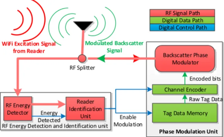
BackFi uses ambient WiFi transmissions that are being sent by a WiFi AP to a standard WiFi client as the excita-tion signal. The tag receives the WiFi signal, modulates data on the received WiFi signal, and backscatters the signal to the AP. The architectural design of the BackFi tag is shown in Fig. 2. IoT sensor consists of BackFi tag and a sensor populating the data in the tag data memory unit.
4.1
The BackFi Link Layer Protocol
First, we describe how a BackFi AP activates and gets a BackFi tag to backscatter information. The protocol pro-ceeds in two stages as described below.
How is the tag activated?
Whenever a BackFi AP transmits, if it is willing to receive backscatter communication, it follows a special protocol be-fore transmitting the WiFi packet. Specifically, like in prior work [27], it transmits aCTS_to_SELFpacket to force other WiFi devices to keep silent. Next it transmits a series of short pulses to encode a pseudo-random preamble sequence. If the preamble bit is one, then a pulse is transmitted and if its zero, no pulse is transmitted. The preamble is16bits long and each bit period lasts for a1µs. The preamble is meant to be the signal to the BackFi tag that the BackFi AP is willing to listen to backscatter transmissions. Note that a preamble can be unique to a particular BackFi tag that is connected to this BackFi AP and can be used to select which BackFi tag gets to backscatter at that instant. In such cases, a tag only backscatters when it detects the preamble meant for it.
A BackFi tag by default is in an energy saving sleep mode if it has no data to transmit. If it has sufficient data to trans-mit (potentially after a sensor has collected enough data), the tag wakes up and listens for its preamble from the BackFi AP. To listen and detect the preamble, the tag uses an energy efficient detector circuit. To build our preamble detector we leverage a large body of work done in low power wake up radio design [40, 18, 36, 37]. These detectors work at power
consumption between98nW [40] to7.5µW [18], and can
detect input signals with power between−41dBm and−56
dBm. The design has an envelope detector, a peak finder, a set-threshold circuit and a comparator. The envelope detec-tor removes the 2.4 GHz carrier frequency from the received signal and the peak detector detects and holds the peak am-plitude of the received signal after envelope detection. The set-threshold circuit obtains the output of the peak detector and outputs half the amplitude as the threshold. Finally the comparator compares the signal after the output of the
enve-lope detector with the threshold and outputs one bit when-ever the received signal is greater than the threshold value and a zero bit otherwise. The comparator outputs a bit de-cision every microsecond, corresponding to the bit period in the preamble. Finally digital logic on the BackFi tag cor-relates the detected16-bit long sequence over sliding win-dows with the known preamble associated with that tag, and if there is a match it activates the rest of the backscatter cir-cuitry to begin modulation of its data.
Tag Data Memory Channel Encoder Backscatter Phase Modulator Enable Modulation RF Splitter
Raw Tag Data Encoded bits
Phase Modulation Unit Digital Data Path Digital Control Path
RF Signal Path
WiFi Excitation Signal from Reader
Modulated Backscatter Signal
RF Energy Detection and Identification unit RF Energy Detector Reader Identification Unit Energy Detected
Figure 2: Architecture of the tag used in BackFi: Once the tag senses the WiFi excitation signal from the reader, it wakes up the modulation subsystem. The tag then reads the data to be uploaded and modulates it on the excitation signal by selecting discrete phase using theBackscatter Phase Modulator.
How does the tag modulate its data?
Fig. 4 shows the various timing events and packet format used by the BackFi tag. We will describe their functionality in detail later in this section, here we give a brief overview. Once the excitation energy is detected and the reader is iden-tified (which lasts16µs), the tag goes into asilent period
that lasts for another16µs. During this time the tag will sup-press any backscatter transmission, which allows the reader to estimate the channels needed for self-interference can-cellation as described in Sec. 4.2. After that the tag
trans-mits its own preamble sequence for 32 µs that is known
at the BackFi reader. Using this sequence the reader can estimate the channels it needs for decoding the backscatter data. This sequence is a pseudo random with very high auto-correlation, and is used by the reader to find the symbol tim-ing from the tag.
The tag then sends its data payload by phase modulating the received signal. Specifically, let’s say the tag is using QPSK modulation, hence there are four symbols[ejθ1,ejθ2,
ejθ3,ejθ4]in the constellation map separated by 90 degrees
on which two bits of information can be modulated. The tag reads the data that needs to be transmitted, picks out two bits at a time, maps it to the appropriate QPSK symbol and then multiples the received excitation signal from the WiFi trans-mitter with the corresponding phase signal,ejθi, i= 1. . .4 to modulate the data on to the WiFi signal. The specific cir-cuit by which the phase modulation signalejθi is generated is a well studied problem and has been widely used in RFID
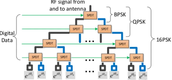
RF signal from and to antenna
...
...
SPDT SPDT SPDT SPDT SPDT SPDTShorted RF terminals with transmission lines of different lengths
SPDT SPDT SPDT
...
Digital Data 16PSK 1 j e ej2 QPSK BPSK 3 j e ej4 ej13 ej14 ej15 ej16Figure 3:Structure of the backscatter phase modulator used in the tag of BackFi: The four digital signal can be used to select one of the 16 possible phases at the leaf of the tree. The incoming RF signal traverses from the top input port all the way to the selected leaf node and is reflected back from the short circuited terminals to the input RF port.
tags [49]. Fig. 3 shows the detail of the RF phase modulator we use in the BackFi tag.
The phase modulator consists of several RF Single Pole Double Throw (SPDT) switches that are connected in a bi-nary tree structure. These switches can pass incoming RF signal to one of the two ports. These switches can be con-trolled using digital signals and the tag uses the data to be modulated as the control signal for these switches. At the leaf of the switch tree, different lengths of RF traces are connected. These trace lengths are designed specifically to achieve the discrete phase shift required for the supported constellation. The number of SPDT switches is determined by the number of constellation points that are supported. For example, for BPSK only one switch is needed, for QPSK three switches are needed and for 16-PSK 15 switches are needed. Also, if the tag can support higher modulations, then all the lower modulations can also be supported. For example, the design in Fig. 3 can support 16-PSK, QPSK, and BPSK, by appropriately preventing some of the switches from toggling as shown in the figure.
To improve the performance of the link the tag also em-ploys simple channel encoding using convolutional codes. The convolutional codes are powerful error correcting codes yet their encoders are very easy to implement using few stan-dard digital components which incurs small energy penalty
on the tag. For example, a rate 12 convolutional encoders
with constraint length of 7, will require 6 shift registers and 8 XOR gates.
Tag Symbol Rate: The BackFi tag also has a choice on the rate at which it will generate the phase modulation sym-bols by controlling the switching frequencies on the SPDT switches. The trade-off here is that higher frequencies con-sume more power and energy, hence the actual rate to use is a function of how much energy is available either via bat-teries or harvesting. In BackFi tags, this is a configurable
parameter ranging from0.01megasymbols/second (MSPS)
to2.5MSPS.
Next, the BackFi AP after receiving the phase modulated, backscattered signal proceeds to decode the tag’s data. As discussed in the previous section, the two key challenges
Silent Mode
Preamble & Synchronization
Tag Data Modulation 16µs
32µs CTS-to-SELF
Detection &
Identification Energy detected by the tag and the reader AP is identified
Tag goes into silent mode during which reader estimates environmental contributions
Tag modulates with a known preamble which the reader uses to estimate forward backward channel and to find symbol boundary
Tag modulates the payload data 16µs
Timeline of various events at the reader and its backscatter client Excitation signal / WiFi packet
Figure 4:The BackFi AP first sends out the CTS-to-SELF to force other WiFi into silent mode. It then sends out the energy detection and identification data to its backscatter client. Once the WiFi ex-citation signal is received by the tag, it goes through sequence of operations shown above before modulating its data on the excita-tion signal. The excitaexcita-tion signal is in fact a WiFi packet meant for a regular WiFi client which receives and decodes the WiFi packet without ever noticing the presence of the backscatter communica-tion that is happening simultaneously.
here are wideband self-interference cancellation and time-varying decoding. We describe how BackFi addresses these challenges next. Note that the channel model of the signal received back at the reader with BackFi is exactly the same as standard RFID backscatter and has been derived in Eq. 3, the only difference of course is thatx(t)is the WiFi OFDM signal instead of a tone.
4.2
Self-Interference Cancellation
Like conventional RFID systems, the tag’s backscatter sig-nal in BackFi is buried under strong self-interference. This interference stems from two sources: direct leakage from the AP’s transmit chain to the receive chain and from reflections of the WiFi transmission by non-tag objects in the environ-ment. But unlike the single tone excitation signal in RFID, BackFi’s excitation signal is a wideband WiFi OFDM sig-nal. Because of the wideband nature, scaling the excitation signal by a single attenuation and phase shift is not sufficient to model the self-interference. This is because different fre-quency components of the WiFi signal add constructively or destructively due to the multi-path effect which results in frequency dependent scaling and phase shifts. However, this problem has been studied extensively in recent years for designing full-duplex radios [12] where self-interference needs to be suppressed to be able to simultaneously listen to weak signals that are being received. The difference in BackFi from those scenarios is that the backscatter signal (which corresponds to the weak signal we want to receive) is a modified version of the transmitted signal, whereas in standard full duplex that is a completely independent signal originating from another sender. So BackFi leverages the recent work on full duplex, but modifies it appropriately to handle the fact that backscatter signals are highly correlated with the self-interference signal.
We briefly review the design of self-interference cancella-tion systems for completeness, but refer the reader to prior work [12] for a complete description. Self-interference can-cellation systems first estimate the channelhenv(t)that the
leaked and reflected signal have gone through before reach-ing back at the receiver. This estimated channel distortion
Cancellation filter Circulator Σ TX RX Environmental Reflections { 𝑥 ∗ ℎ𝑓.𝑒𝑗𝜃} ∗ ℎ𝑏+ 𝑥 ∗ ℎ𝑒𝑛𝑣 x Client
Estimating Forward and Backward Channel MRC & Demodulator {𝑥 ∗ ℎ𝑓.𝑒𝑗𝜃} ∗ ℎ𝑏 Viterbi Decoder ℎ𝑏 ℎ𝑓 ℎ𝑒𝑛𝑣 Tag Data 𝑒𝑗𝜃 ℎ = ℎ𝑒𝑛𝑣 𝜃 Downlink x Tag Data
Figure 5: Architecture of the reader used in BackFi: The reader transmits the excitation signalxwhich is actually a WiFi packet meant for a client. This signal is reflected by the environment, which the reader cancels usingcancellation filter. The residual sig-nal after cancellation is used to estimate the forward and backward channel from and to the tag. The reader then applies MRC to esti-mate the tag dataθˆ, which is further improved by passing it through Viterbi decoder.
is applied to a copy of the transmitted WiFi signal to recre-ate the self-interference accurrecre-ately, and the distorted signal is then subtracted from the received signal to eliminate self-interference. The distortion application and subtraction hap-pens in two stages, analog and digital. Analog cancellation is necessary to ensure that the receiver’s ADC is not satu-rated by self-interference which would drown out the weak backscatter signal before being received in baseband. Ana-log cancellation is implemented using a combination of RF FIR filters and couplers [12], but cannot completely elimi-nate self-interference due to the imprecision of analog com-ponents. Hence a second digital cancellation stage is em-ployed after the signal is sampled by the receiver’s ADC to eliminate the residual self-interference. Digital cancellation is implemented via digital FIR filters. Fig. 5 shows the de-sign.
If we directly apply the prior design, it will end up can-celing parts of the backscatter signal too. The reason is that prior design aims to accurately estimate the non-linear transfer function that captures the relationship between the transmitted signal and the received signal [12]. But as we have shown in the previous section, the backscatter signal is actually a non-linear transformation of the transmitted sig-nal. If naively applied, prior designs would end up canceling the backscatter signal too which would reduce the SNR and throughput of tag’s transmissions back to the reader.
To tackle this, BackFi’s link layer design ensures that dur-ing the channel estimation phase of self-interference can-cellation, there is no backscatter transmission. Specifically, when a BackFi tag is excited by a WiFi transmission, they do not instantly start backscatter. Instead they employ asilent periodof 16µs as shown in Fig. 4, during which they do not backscatter, and only then start modulating their data on to the received signal and performing backscatter. We show experimentally that this small silent period is sufficient for the reader/AP to estimate the self-interference channel and perform cancellation for the rest of the WiFi packet. Since
there is no backscatter during the channel estimation phase, self-interference cancellation does not model the backscatter reflections and therefore they are not affected by cancella-tion.
At this stage, the reader/AP is left with just the non-linear backscatter reflection from the tag, and its goal is to decode the data. We describe this step next.
4.3
Decoder Design of BackFi
As reviewed before, since the WiFi signalx(t)is wide-band, the excitation signal received at the tagz(t) =x(t)∗ hf(t)cannot be considered as simple scaled and phase shifted
version of x(t) as with standard RFIDs. Hence after the
removal of the self-interference, the residual signal at the reader after down-conversion to baseband is given by
ytag(t) = h (x(t)∗hf(t))ejθ(t) i ∗hb(t) | {z } tag signal . (4)
Here, the signal x(t) is the WiFi transmission that the reader is sending. This signal is wideband and varying but known to the reader. The channelshfandhbare the forward and the backward channels. These channels can be consid-ered time invariant for the duration of the tag packet but are unknown. The goal is of course to recover the tag signal
ejθ(t)from the above equation. This is challenging because
the tag signal is being modified by a time varying unknown channel, namelyx(t)∗hf(t). Contrast this with standard RFID decoding at the reader in Eq. 2, where the tag sig-nal is being modified by a time-invariant channel since both
hf(t)andhb(t)are time-invariant for the duration of the tag packet. We describe how BackFi tackles this time-varying decoding problem next.
4.3.1
Estimating the forward/backward channels
First, the BackFi AP estimates the forward and backward channels,hf(t)andhb(t). We can assume these channels to be time invariant for the duration of the tag packet, hence to estimate them we use a standard communication technique: a preamble. Specifically, after the tag detects that it should backscatter and stays quiet for thesilent period, it modulates a constant phaseejθpreon the backscatter signal for a fixed period of32µS. Thus during thepreamble intervalthe re-ceived tag signal at the reader is given by
ypre(t) =x(t)∗[hf(t)∗hb(t)].
Now since x(t)is known, this becomes a standard
chan-nel estimation problem encountered in every communication system. We omit the details of the channel estimation tech-nique and refer the reader to the vast amount of literature on this topic [38]. The channel estimation algorithm thus calculates the value ofhf(t)∗hb(t).
Note that the above procedure only provides an estimate of the combined forward-backward channel, but not the in-dividual channels. Hence the decoding step has to work only with the combined channel estimate.
j1= ejq1 j2= ejq2 z1 z2 z3 z4 z5 z6 Symbol Period Sampling Period j1z1 j1z2 j1z3 j2z4 j2z5 j2z6 Backward Channel Length
}
j1 ( z1 hb1+z2 hb2 ) MRC Sample ignored j1 ( z2 hb1+z3 hb2 ) j2 ( z4 hb1+z5 hb2 ) j2 ( z5 hb1+z6 hb2 )}
MRC j^2 j1 ^ Tag Data Excitation Signal at Tag Tag modulator ModulatedTag Data Received tag
backscatter
=
hb1 hb2 Convolution with backward channel=
Estimated tag data Maximal Ratio CombiningTag Modulation Backward Channel Convolution MRC Decoder at Reader
j1z3 hb1+j2z4 hb2 )
Figure 6:Discrete time representation of the design of BackFi: The samples of the WiFi excitation signalzis multiplied by the dataφat the tag.The modulated signal then passes through the backward channelhb. The sampling period of WiFi is much smaller than the symbol period of the tag. This results in multiple copies of the tag data over several sampling period at the reader. These multiple copes are combined optimally by the MRC to estimate the tag dataφˆ.
4.3.2
Decoding the Tag Data
The final step is decoding the tag data itself. BackFi’s key insight here is the fact that symbol times for tag data are quite long due to the need to conserve energy at the tag. Specifi-cally the tag modulates data by changing the phase term in
ejθ(t). Changing the phase is implemented by switching a
transistor as described in Sec. 4.1. Transistor energy con-sumption scales linearly with switching frequency, hence tags use low rate switching frequencies. Typical transistor switching frequencies in tags are on the order of0.5−2.5
MHz in tags, hence the symbol period in a tag is between
500−2000ns. How can we exploit this insight to decode
the data?
Our observation is that the delay spread in a typical
chan-nel between the reader and the tag is far smaller than500
ns. In other words the length of the channel is far smaller. Intuitively this is because typical distances between a reader and a tag are around10m, so even accounting for reflections the extra multipath delay spread is small. Hence a channel usually lasts for50−80ns. But the symbol period from the tag is much longer at500ns, hence for the duration of the channel, we can consider the tag signal to be an unknown constantejθc. BackFi leverages this insight to decode, it looks at the part of the symbol period (with some guard pe-riods at the start and end of the symbol time as shown in Fig. 6 and tries to find the value of the constant phase within that period.
Specifically, with a constant phase from timet1−t2, we
can rewrite the decoding equation at the reader as:
y(t) = (x(t)∗[hf(t)∗hb(t)])ejθc+N;t1≤t < t2 (5)
Note that all the terms exceptejθc are known in the above equation. A natural next step might be to divide y(t)by
x(t)∗[hf(t)∗hb(t)]but this works poorly because it will also divide the noise term in the above equation and in many scenarios amplify it.
To tackle this, we turn to an old trick in communication theory: maximal ratio combining. To see how this works it helps to write the above equation in the discrete domain (the
representations are equivalent assuming sufficient sampling rate) as follows:
ytag[n] =ejθ[n1]xTn,L+Mhfb ∀n∈[n1, n2] (6)
HereLis the length of the forward channel, and M is the
length of the backward channel. Thehfbis the lengthL+
M vector of the combined forward-backward channel and
xn,L+M= [xn. . . xn+L+M−1]
T
is a vector of lengthL+M
constructed using the excitation datax[n], and we have as-sumed that the tag signal is constant for the period[n1, n2]. The above equation is simply a discrete version of Eq. 5 with the discrete convolution operation represented as dot product of vectorsxn,L+Mandhfb.
Notice that the tag signal is expressed in terms of the forward-backward channel that we have estimated earlier, and therefore individual estimates of the forward and the backward channel are not needed. Also note that the tag modulation is constant forn2−n1+1interval which is larger
thanL+M, this is restating the same insight that length of the forward and backward channels is much smaller than the
symbol period of the tag. So we will haven1+n2−LM
different values ofytag[n]which contains information of the
unknown but constant tag signalejθc. We can leverage this fact to combine all these values to obtain the most likely value ofθc that could have produced those sequence of ob-servations ofytag[n]over the period[n1, n2]using maximal
ratio combining (essentially the same as temporal diversity combining). Specifically MRC would use the following for-mula to estimateθc, ˆ θc= Pn2 n=n1yˆtag[n] {y tag[n] P |yˆtag[n]|2 , (7)
whereyˆtag[n]is the expected tag backscatter signal
with-out the modulation and can be computed as
ˆ
ytag[n] =xTn,L+Mhfb ∀n∈[n1, n2],
and{is the complex conjugate operator. Essentially the dif-ferent measurements ofyover that interval are weighted
ap-propriately and combined to produce the most likely esti-mate ofθc.
At this point, we have a robust estimate of the tag data for that symbol. The algorithm is repeated for all the symbols in the tag packet. There may still be decoding errors of the n-PSK symbols, which we can correct by using a standard channel code on top. In BackFi, we use a convolutional code at the tag to improve the link performance. The coding pro-vides additional robustness and is decoded using a standard Viterbi decoder [38], we omit the details for brevity.
5.
IMPLEMENTATION
We build a prototype of both the AP and tag of BackFi system. We describe their implementation details below.
5.1
BackFi AP
The BackFi AP is implemented using WARP software
radios. The WARP incorporates a standard20MHz WiFi
baseband operating in the2.4 GHz range. We also use the
same implementation on a WARP board to work as a WiFi client in our experiments. Further the decoding logic for backscatter signals is also implemented in the WARP FPGA [7]. For self-interference cancellation, we reproduce the recent design on single antenna cancellation [12, 11].
5.2
BackFi Tag
The IoT sensor is designed to operate across the2.4GHz WiFi channels. The prototype uses a2.4GHz omni-directional antenna that can receive and backscatter WiFi signals and
has a gain of3 dB. In our current prototype, logic
imple-mented on a Kintex Kc705 board [6] supplies the data to be transmitted and configures the backscatter circuitry. This can be replaced with custom ASIC in a full design which would consumes significantly lower energy.
The backscatter circuitry implements two components on
the uplink: the detector, andthe modulator. The
modula-tor implements BPSK, QPSK and 16-PSK modulation. The phase modulation is implemented using SP4T switches. We chose phase modulation instead of n-QAM because this will result in the least amount of RF signal degradation during the backscatter modulation.
5.2.1
Energy consumption efficiency metric
In order to compare various implementation choices for IoT sensor, traditionally Energy per Bit (EPB) measured in average joules of energy required to transmit one bit of in-formation has been used as a metric for energy efficiency. However, EPB varies significantly with the implementation platform. For example, the EPB for an IoT sensor imple-mented using off-the-shelf discrete components can be or-ders of magnitude larger than the EPB for IoT sensor im-plemented in a micron ASIC design. Even for the sub-micron ASIC designs, EPB varies significantly depending on the technology node chosen (say 65-nm CMOS node vs 45-nm CMOS node) and the design choices (low power sub-threshold CMOS design vs traditional strong inversion CMOS design). BackFi’s contribution is in showing how the EPB of an IoT sensor are related to each other for various communi-cation parameters on a particular implementation platform.
For example, if an IoT sensor can choose BPSK or QPSK for communication, an interesting question may be, what is the relationship between the EPB of these two cases. While to the first order the EPB of these two cases should be the same and only the throughput should double going from BPSK to QPSK, a more detailed analysis shows that EPB is not the same for these two cases.
To understand why, let us refer to the architecture of the RF modulator as shown in Fig. 3. While BPSK requires only one SPDT switch, the QPSK requires three SPDT switches with double the throughput, therefore the EPB of the mod-ulator goes up by a factor of 32. Likewise, for 16-PSK we need 15 SPDT switches, but the data rate improvement is only 4 times compared to the BPSK, therefore the relative EPB for modulator increases by a factor of 154. Also, power consumption in IoT sensor has two major components, the first one is dynamic power resulting from the charging and discharging of capacitors in various sub-systems of the IoT sensor as digital logic is computed, and the second is static power which is either due to leakage, or due to constant current required by some of the analog components in the IoT sensor. Because of the static power, the EPB is also ef-fected by the symbol rate of the IoT sensor as the device takes longer time to transmit the same amount of data. For example, an IoT sensor can reduce the symbol rate which results in the improved SNR at the BackFi from MRC, but at the same time the static power consumption of the circuits will increase thereby increasing the overall EPB.
In order to show the energy efficiency trade-offs associ-ated with the various choices offered by BackFi and to de-couple them from the energy efficiency gained from actual choice of the implementation platform, we will present the remainder of the results using unit-less Relative Energy per Bit (REPB). We will first describe how energy consumption is modeled for our exemplary IoT sensor as shown in Fig. 2 and then show how we can compute its REPB for different parameter choices.
We have modeled the EPB of the tag by identifying the major power consumption modules of the IoT sensor archi-tecture shown in Fig. 2. The three major contributors for
EPB of this design are: the RF modulator, the channel
en-coder and the memory. As discussed earlier, the EPB of RF modulator varies depending on the chosen modulation index because the ratio of bit rate to the number of SPDT switches varies as we change the modulation index. In our current en-ergy model we have computed the static and dynamic EPB of RF modulation unit by appropriately scaling the data pro-vided for an industry standard modulator, the Analog De-vices ADG904 [1].
BackFi uses a convolutional encoder to reduce bit error rates (BER). The exact EPB contributed by the encoder cir-cuit is a very small fraction of the total EPB required for communication because convolutional encoders with mod-erate constraint length ( 7 in BackFi) require only 6 shift registers and a few XOR gates to encode the IoT sensor data. But the major EPB contribution comes from the coding rate associated with the convolutional encoder. For example, a
1
mod-ulator because the IoT sensor will transmit twice the actual amount of data on the channel. Likewise, a rate23 code will bump the RF modulator’s EPB by a factor of32and so on.
And finally BackFi also models the EPB associated with the memory read of the data in the IoT sensor. Because memory reads are performed for the sole purpose of backscat-tering the data to the BackFi’s reader, we believe it is very important to include the read energy associated with the mem-ory element as part of the overall EPB. In our current energy model we have computed the static and dynamic EPB of the memory read by using data provided for Cypress Semicon-ductor CY62146EV30 [2].
Using the above energy modeling technique we can now compute the EPB required for a particular choice of
com-munication parameters:channel code rate, symbol switching
rate, modulation index
EPB = EPBmem+ EPBmod+ EPBenc. (8)
HereEPBmemis the EPB associated with the memory read
inside the IoT sensor. This has two parts, the dynamic EPB that is dependent on the number of read operations per bit of data of IoT sensor, and the static part that is dependent on the symbol switching rateTs,
EPBmem= EPBmem,read+ Pmem,static×Ts. Similarly, we can express the EPB associated with the
con-volutional encoderEPBencand the modulatorEPBmodwith
their constituent dynamic and static EPB.
In order to obtain the unit-less REPB, we use EPB for one set of such communication parameters as a reference and then divide the EPB for all the other choices with this refer-ence EPB. In our current evaluation, we use12rate code with
BPSK modulation with symbol switching rate of1Mbps as
reference communication parameters to compute the refer-ence EPB. Based on the datasheets of the referred parts we computed the EPB for this reference case to be3.15pJ/bit.
Also, we have excluded the EPB associated with the en-ergy detection logic as we believe their contribution to the overall EPB will be insignificant. The energy detector is based on prior work on wake up radio [40, 31]. The power
consumption of this detector is around100nW. The energy
detection needs to be done once for every backscatter packet and lasts for16µs. A typical backscatter packet will have 1000 bits of information in it. Based on these information the EPB contributed by the detection logic is in femtojoules per bits which is practically negligible. The wake up radio
can detect input signals as weak as−41dBm, which
pro-vides sufficient range to wake up the tag radio even at a
dis-tance of5m from the AP. The same detection circuitry can
be used to implement the downlink communication to the tag from the AP reader. The protocol for downlink communica-tion has been described in prior work [27]. BackFi reuses this design for the downlink and provides similar through-puts of20Kbps. Since our focus in this work is on the up-link design we will evaluate it in detail in the next section by using REPB given by Fig. 8 as one of the metrics.
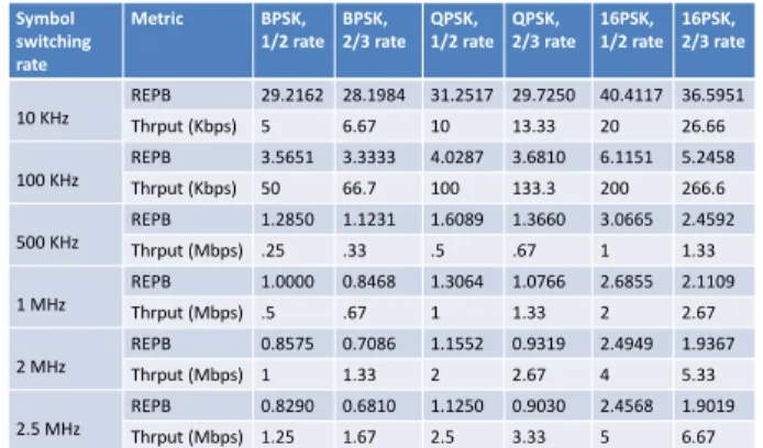
Symbol switching rate Metric BPSK, 1/2 rate BPSK, 2/3 rate QPSK, 1/2 rate QPSK, 2/3 rate 16PSK, 1/2 rate 16PSK, 2/3 rate 10 KHz REPB 29.2162 28.1984 31.2517 29.7250 40.4117 36.5951 Thrput (Kbps) 5 6.67 10 13.33 20 26.66 100 KHz REPB 3.5651 3.3333 4.0287 3.6810 6.1151 5.2458 Thrput (Kbps) 50 66.7 100 133.3 200 266.6 500 KHz REPB 1.2850 1.1231 1.6089 1.3660 3.0665 2.4592 Thrput (Mbps) .25 .33 .5 .67 1 1.33 1 MHz REPB 1.0000 0.8468 1.3064 1.0766 2.6855 2.1109 Thrput (Mbps) .5 .67 1 1.33 2 2.67 2 MHz REPB 0.8575 0.7086 1.1552 0.9319 2.4949 1.9367 Thrput (Mbps) 1 1.33 2 2.67 4 5.33 2.5 MHz REPB 0.8290 0.6810 1.1250 0.9030 2.4568 1.9019 Thrput (Mbps) 1.25 1.67 2.5 3.33 5 6.67
Figure 7: Table provides BackFi tag’s relative EPB and corre-sponding data rate for different choices of modulation, coding and tag symbol switching rate.
6.
EVALUATION
We evaluate BackFi’s design in an indoor environment in our lab with rich multi-path reflections and dense WiFi de-ployment. Our evaluation reveals the following:
• BackFi provides three orders of magnitude higher
through-put, an order of magnitude higher range compared to the best known WiFi backscatter system [27, 25]. Specifically
BackFi can provide a throughput of5Mbps at 1m range
and a throughput of1Mbps at5m range from the BackFi
AP.
• BackFi’s throughput and range are comparable to
tradi-tional RFID platforms such as Ekhonet [55]. The key ben-efit of course is that BackFi is a WiFi back-scatter system and does not need dedicated reader infrastructure or fre-quency spectrum.
• BackFi has negligible (less than 5%) impact on the
stan-dard WiFi network’s throughput even when the IoT sensor is concurrently backscattering WiFi signals.
6.1
Throughput, Range, and REPB
First, we evaluate the trade-off between throughput, dis-tance, and REPB for BackFi. For any given disdis-tance, BackFi can deliver a set of throughputs by picking the appropriate combination of symbol switching rate, modulation, and cod-ing rate. Each choice of symbol switchcod-ing rate and modu-lation has a different throughput as well as different REPB as described in Section 5.2.1. Fig. 7 shows the REPB and throughput for every combination of symbol switching rate, modulation, and coding rate. The EPB for each of the these entries can be calculated simply by multiplying REPB and EPB of the reference parameters ( BPSK, 1/2 rate with sym-bol switching rate of1MHz).
Note that while throughput monotonically increases from left to right in the table, REPB does not. For example, at an IoT sensor symbol switching rate of 1 MSPS, going from (QPSK, 1/2) to (QPSK, 2/3) results in a decrease in REPB. The reason is that energy needed to switch from 1/2 rate to 2/3 rate is not significant compared to the other energy con-tributions for this technology node and the increased through-put causes the REPB ratio to decrease. However, if at a cer-tain range if the link SNR is such that both (QPSK, 1/2) and (QPSK, 2/3) encoded backscatter signals can be decoded at
100 Kbps 10 Kbps
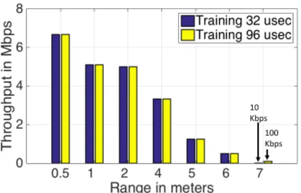
Figure 8: Relationship showing range of BackFi and maximum possible data rate possible for two different training times. At 7 meter, if we increase the preamble duration from 32µsec to 96
µsec, it provides10×improvement in the throughput.
the reader, then BackFi would never use (QPSK, 1/2). The rate adaptation algorithm would always pick the modulation, coding rate and symbol switching rate combination with the lowest REPB since the most precious resource here is en-ergy, whether it comes from harvesting or batteries.
Next, we evaluate the throughout and range performance in our testbed. For these experiments we use our WARP based BackFi implementation for the BackFi AP to decode the IoT sensor’s backscatter signals. The BackFi AP and the WiFi client are placed such that the maximum WiFi bit rate
is 54 Mbps. They are configured to run on WiFi channel-6
in the 2.4 GHz range. The results for other WiFi channels are similar and not presented due to lack of space.
Impact of Range on Throughput: The BackFi’s IoT sensor is placed at distances ranging from0.5m to7m. For each distance, we cycle the IoT sensor through all combinations of symbol switching rates and modulations, and then cal-culate throughput for combinations that can be decoded at the reader. In each iteration of the experiment, the BackFi’s AP reader transmits 1 to 4 ms long packet at 24 Mbps bi-trate including the backscatter start sequence as discussed in Sec. 4.1. The IoT sensor backscatters for the entire dura-tion of the packet and stops when its detecdura-tion logic signals the end of the transmission. We repeat the experiment 20 times at each combination of distance and BackFi through-put. Fig. 8 plots the maximum throughput achieved as a function of range for two different preamble duration of32 µs and96µs.
Results: As we can see, BackFi is able to achieve a
max-imum throughout of around6.67Mbps at a distance of50
cm. For more practical ranges, BackFi achieves a
through-put of 1 Mbps at a distance of5m and around5Mbps at a
distance of1m. This performance is three orders of magni-tude better in throughput at the same range as compared to the best known WiFi backscatter system [27, 25]. Note, at 7 m the increased preamble duration of96µs shows a10× in-crease in the throughput. This is due to the fact that a shorter preamble results in an inaccurate estimate of the forward-backward channel which limits the SNR of the backscattered
signal. Hence, for32µs preamble, the IoT sensor
compen-Figure 9:Each plot is BackFi’s REPB for corresponding through-put achieved for the range varying between 0.5 m to 5 m. For exam-ple, we see that at a distance of 2 m to achieve 4 Mbps throughput we need to spend much more energy per bit than at a distance of 1m. Also, the vertical line indicates the maximum throughput that is achievable at a given distance between the tag and the reader. sates this loss of SNR by increasing the symbol period to
10×, which in turn reduces the throughput.
To analyze the energy efficiency that BackFi link achieves for different combinations of throughput and range, we plot REPB as a function of throughput achieved for different ranges in Fig. 9. To read this graph, note that for every value of
range we studied (0.5m, 1 m,2 m, 4m, 5m), we have a
different curve (with a different color). Now for each partic-ular range, we check what combinations of tag symbol rate, modulation and coding rates employed at the tag can be suc-cessfully decoded at the BackFi AP. For each throughput, we look up all combination that achieve it, and their REPB from Table. 7 and choose a minimum REPB and plot a point. All the points for that particular range are now joined by lines to show the feasible points for each range.
Fig. 9 shows that for a given range, throughput increases are obtained by either increasing the symbol switching rate, moving to a denser modulation or higher coding rate or some combination of all three. Each one of these increases energy consumption as expected, which leads to the step increases in REPB. Of course certain throughputs simply cannot be supported at a given range because the link’s SNR is not strong enough to decode the data. The vertical line indicates the maximum throughput that can be achieved for a given distance between the tag and the BackFi’s reader. Hence we see the curves stopping after a certain throughput for
differ-ent ranges. Overall REPB lies between 0.5 to3 for most
combinations.
Next, we plot how REPB changes as a function of range assuming we want the same throughput. For this experiment
we pick two throughputs,1.25Mbps and5Mbps, for which
we want to optimize the communication link. For each value of range, we pick the combination of tag symbol rate, mod-ulation and coding rate that can achieve those throughputs if there are any. Among the possible combinations we pick the one with the lowest REPB and plot it for that range. Fig. 10 shows the REPB as function of range for these two through-puts.
Figure 10: For achieving fixed throughput using BackFi for dif-ferent distance, the tag needs to spend more energy as it goes far away. For achieving 1.25 Mbps we need to spend2.5×more than power needed for reference modulation, coding and switching rate. Here we see expected results. For a fixed throughput, as we go to higher ranges we need to use lower coding rates. In our current design we only support two coding rates: 1/2 and 2/3. Hence for all these experiments we see the REPB change between two levels corresponding to the shift from higher coding rate to lower.
6.2
Reconstructing BackFi’s performance
In this section, we aim to understand where do BackFi’s benefits come from. As discussed before, BackFi’s design
has two key components:self-interference cancellation and
the decoding algorithm. We try to shed light on the impact of each component on BackFi’s performance.
Impact of self-interference cancellation: This component helps eliminate the unwanted leakage and environmental re-flections from reducing the backscatter signal’s SNR. Any uncanceled interference directly acts as noise to the backscat-ter signal and reduces throughput. To evaluate its impact we measure the SNR for the backscatter link at the reader and compare it to what the SNR would have been if cancellation was perfect. The experiment is conducted by placing the BackFi AP and the IoT sensor at 30 different locations in the testbed. For each location, we do ten runs where during each run we let the BackFi IoT sensor backscatter a known packet and measure the forward and backward channels from the tag using a vector network analyzer. In this scenario the VNA [42] acts as the BackFi AP and is being used so that we can measure the channels accurately for comparison. Next we perform the actual backscatter communication with a BackFi AP and decode the data after self-interference can-cellation. We also compute the SNR of the demodulated phase modulated symbols from the tag and compare it to the SNR predicted by the channel measurement from the VNA. We plot these two SNR values for each run and each loca-tion as a scatter plot in Fig. 11(a). As we can see cancel-lation works well, the median degradation in SNR is less than2.3dB. This is consistent with earlier self-interference cancellation results from prior work [12, 11] which report a self-interference residue of1.7dB after cancellation.
Impact of Symbol Time and MRC: The second compo-nent of BackFi’s decoder at the BackFi AP is the algorithm for dealing with the time-varying decoding problem. The al-gorithm has two key components: exploiting the larger sym-bol times from the tag packet to make an approximation that
(a) (b)
Figure 11: (a)Demonstrates the effect of imperfect cancellation on the degradation of the measured SNR vs the expected SNR at the reader of BackFi. When the cancellation is imperfect the environ-mental components are no longer completely removed and this acts as interference to the backscatter signal from the tag.(b) Demon-strates the diversity gains of MRC : as we increase the symbol time period, we have more samples for averaging, hence it improves the SNR. This increase in SNR results in lower bit error rate (BER) for a given modulation.
the channel can be converted into a simplified time invariant system and then apply MRC to solve it. MRC helps amplify the SNR of the signal by combining signal energy across time appropriately. Hence the key factor here is the tag sym-bol period which is inversely proportional to the tag symsym-bol rate. To show the impact we plot the BER vs tag symbol rate for two modulations and a fixed coding rate of 1/2. The ex-pectation is that as the tag symbol rate decreases and symbol time increases, the MRC gain will drive the BER down like a waterfall curve. Fig. 11(b) plots the BER as a function of decreasing tag symbol rate. As we can see, for this particu-lar placement of AP and tag, at the highest tag symbol rate the BER is high between10−2−10−3. As tag symbol rate
decreases, the time diversity gain from MRC kicks in and
BER drops down to between10−4−10−5. This technique
essentially points out the trade-off between throughput and range and why it exists.
6.3
Performance in typical WiFi Networks
BackFi tags only backscatter data when the WiFi reader is transmitting and they are activated by the reader with the activation sequence. The best candidate for the WiFi reader device is clearly the AP since it is likely the most dominant transmitter in a typical network. Nevertheless, in a typical network that is fully loaded (i.e. there is always outstanding traffic to transmit from the AP or a client), the AP will be transmitting a fraction of the time which would imply that the BackFi link would also be active for the same fraction. We evaluate the throughput BackFi can provide under such typical network conditions.
To conduct this experiment, we took traces from open source data [24, 47, 41]. The traces are captured for a wide variety of scenarios for heavily loaded networks. If an AP is not loaded and there is a lot of idle channel time, then a BackFi AP can initiate backscatter communication anyway by sending dummy packets just for that purpose. Hence the interesting case is when the network is loaded and backscat-ter opportunities are limited due to contention.
Next, we filter the traces to only contain AP transmissions and replay the collected trace using our WARP based BackFi AP implementation to simulate the same traffic conditions.