72
EXECUTION OF A LAYOUT WORK FOR REHABILITATION OF A MILK
FACTORY IN IZVIN, TIMIS COUNTY WITH EUROPEAN FUNDS
LECTURER PH. D.DRAGOMIR L.1 ; LECTURER PH. D. BÂRLIBA LUMINIŢA LIVIA1 ;
LECTURER PH. D. BÂRLIBA C. 1 ; ASSOC. PROF. PH. D. CALINOVICI I.2;
PROF.PH.D. POPESCU COSMIN1
1Banat University of Agricultural Sciences and Veterinary Medicine”King Mihai I of
Romania” from Timisoara, Romania 2 "Aurel Vlaicu" University of Arad, Romania
Keywords: Total station Leica TCR 805, cadastral plan, stereographic projection.
ABSTRACT
Purpose of this paper is to present a model for preparing and implementing of a layout work for surface construction work in order to put into practice to large projects for the modernization of rural areas and creating new opportunities in the area.
Development work is based on the topographic survey of the investment location and the layout project in order to construct “industrial building" based on investment projects in agriculture.
In order to perform this work it was necessary hardware and software structure very well put together, highlighted in particular by the use of software such as AutoCAD 2013 and Leica GeoOffice Tools.
Topographic surveying for the situation plan were made in the field using a total station Leica TCR 805.
INTRODUCTION
The construction project of Izvin Milk Factory is part of a larger project of the area development that includes a complex (plant) for processing agricultural products, both animal and plant products, mentioned in the General Urban Plan of the town of Recaş:
- extension of the facilities and complementary functions area in the village - extension and location of industrial functions
They will be equipped with the necessary facilities, delimitation of land through fences, respectively depending on the surfaces provided in the Land Registry extracts with their location on the ground surface.
This project is mentioned in the Urban Plan of the town and it consists of a a plot in property and the appropriate by-roads used as pasture (grazing field). As a result of the development of Izvin town, the area will be developed further on from the urban point of view and the built-up area will be expanded up to the limits set in this PUZ (Zonal Urbanism Plan)
MATERIAL AND METHOD
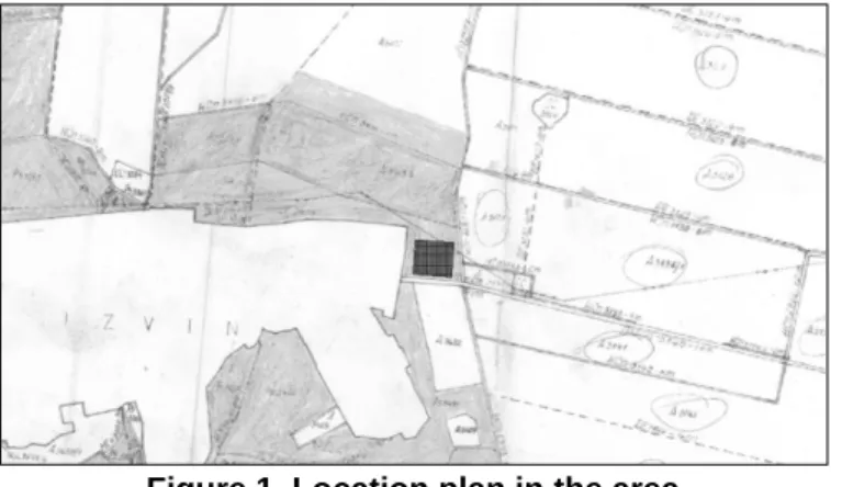
The plot is located in the north-eastern part of the village of Izvin, at the exit of the village on DN6 (National Road 6) towards the commune of Recaş. Adjacent to the plot (nearby) in the Eastern part there is a channel HCn 2973, in the South it lies the DN6 (National Road 6), at the Northern limit the plot borders an arable plot A3435 and in the South-east the built-up area of Izvin village.
73
The area under study, whose beneficiary is S,C. EUROCHESSE S.R.L. is divided into plots for the location of industrial halls and free plots. Taking into consideration the large area, the network equipment of the industrial area will be achieved in stages, as the lands will get a precise destination.
The beneficiary of the work: S.C. EUROCHESSE S.R.L Izvin Data concerning the location:
From the location point of view: the land is placed in the proximity of Izvin village, bordering
on the North side: A3435, arable land
on the West side: the built-up area of Izvin village on the East: the channel HCn 2973
on the South: the national road 6 (ND6).
Figure 1. Location plan in the area
Data concerning the land delimitation
The limits of the land, object of these topographic (survey) works, are marked by a wire mesh fence placed on the entire length of its sides.
The legal status of the land:
The owner of the land is S.C. EUROCHESSE S.R.L Izvin
RESULTS AND DISCUSSIONS
The topographical (surveying) measurements for the lay-out (situation) plan were made in the field by means of a TCR 805 Leica total station.
The station point was established and marked with a FENO type terminal, the apparatus (device) was put into the station, the operation consisting in pressing-on (leveling) and centering, the total station having an optical system centering device. The tripod (three-legged support) was removed and the apparatus (device) was fixed with a screw pump. Once the apparatus (device) centered and pressed-on (leveled), the point station was set with 100 IZ. The measurements are usually performed in local coordinates following that the retro intersection (resection) be calculated in the office, after that the plan is implemented in stereographic coordinates. We established the local coordinates X (N) = 10000 m, Y (E) = 10000 m. Since this is a total station, the difference in level (level difference) between the station point which has Z = 100 and the rest polar (radiated) points was also calculated. The software also requires the working height, this being measured with a ruler, being of 1.63 m, and the height of the prism being established to 2.3 m.
74
Hz = 0.0000 degree was set oriented towards the Catholic Church of Recaş town being well defined (determined). We focused on the cross of the church at its base,
blocking the horizontal movement, setting zero with “enter” for confirmation. The next
operation was to focus the supporting points from the state geodetic base.
The function H – Vz was set from the menu "measurement" so that the device may read only angles; in this case only horizontal and vertical angles are stocked in the memory of the device.
Table 1
Targets pointing towards the supporting points
Order nr. Station points Targeted point x y Orientation (alignment)
1 (100-IZ) Odai signal 484588.64 225872.24 345.5214
2 Catholic Church Recaş 483804.83 228289.1 89.1633
3 Bazoş Vechi Church 479908.8 227166.8 159.5488
4 Chatolic Church Izvin 483781.53 225013.47 246.2401
The resection (retro-intersection) calculation was made in the office resulting the stereographic coordinates of the station point. The coordinates of the station point are X = 488179.852 m and Y = 222005.020 m.
The lifting of the points of detail has been achieved from the station numbered S 100-IZ resulting from the resection (retro-intersection), of which the previous determined points were targeted from the state geodetic network, it was materialized in the field with the FENO terminal. In order to achieve an accurate location (site) plan in the field, a number of 50 points of detail were removed both for the interior elements and for the characteristic elements from the field concerning the neighbors, channels, namely roads adjacent to the cadastral numbers Apj 3434/1; 3434/2; 3434/3/c.
The measurements were made in about 5 hours by a team of three persons. After the completion of the measurements the apparatus (device) was downloaded by using the Toposys program, the data were transferred and set into the program as units in meters, applying to a precision of three decimal points, the data of the different types of angles
wereset in degrees with the accuracy of four decimal places and the data concerning the
direction were set for North and Zenith. After having set them, the data (electronic field
book)were transferred from the instrument in the computer by using the transfer cable and
the data transfer program; they were downloaded under the form of a “idx” file extension
(both polar and absolute coordinates) as well as in Leica Geosystems format “gsi” (Geo
serial interface).
Table 2
Readings and angles obtained after the data downloading and the coordinates of the marginal (contour) points in stereographic 1970 system
Point Code Reading of the
orizontal angle
Reading of the vertical angle
Slope distance
East North Elev
Description
Odai signal 34552140 10044320 03377880
Catholic
Church Recaş 08163300 10004250 - Bazoş Vechi
Church
15954880 10007440 -
Chatolic Church Izvin
24624010 10021880 -
102 IZ 22947420 10016750 01038450
100 IZ 22577590 09943900 01883220
1 22391280 10015770 02513640
2 22794530 09985220 02516300 231884.55808 482284.37931 99.932 c
3 22947980 10017520 02463830 231643.33783 482295.54215 99.530 c
4 23216360 10044480 02242670 231441.45187 482305.29990 101.558 c
5 26600180 09984260 01630700 231417.85343 482309.55936 101.129 c
6 26963640 09999640 01516420 231413.92928 482309.49510 102.111 c
7 29372020 09878370 01542030 231397.06170 482314.66477 101.858 cf
8 26582900 10065150 01447310 231398.59826 482314.59461 101.851 cf
75
10 22094130 09962420 01916860 231324.71753 481980.94407 99.117 c
11 24586470 10065650 01334330 231338.25015 481970.89112 98.775 c
12 26878420 10077660 01163660 231337.57672 481964.02218 99.511 c
13 27251430 10023500 00797020 231268.36519 481766.01577 99.207 c
14 22896110 10028430 00618980 231188.03053 481458.07589 99.496 c
15 21878250 10006960 01331320 231153.50368 481318.31792 99.991 c
16 19409740 10006800 01559870 231171.71901 481312.34743 100.434 c
17 12536260 10139190 00366450 231171.95393 481307.57349 100.456 c
18 14132860 09882220 00768990 231420.84689 481297.13266 100.632 c
19 09049930 10008870 00467480 231679.27189 481281.18531 101.253 c
20 08856850 10061730 00586820 232021.59050 481260.25456 101.006 c
21 15648330 10005200 00975770 232023.00092 481264.11600 102.293 c
22 16566560 09995440 01569920 232027.14424 481250.89596 102.340 c
23 20953480 10024610 01963740 232029.95423 481257.60514 101.622 b
24 20915960 10026330 02001240 232031.46538 481258.08859 101.784 a
25 20921800 10016490 02050180 232383.36367 481234.86335 103.665 c
26 17517440 09689800 01844960 232381.51838 481228.34397 103.108 c
27 17527790 10329220 01804990 232431.04596 481464.48183 102.535 c
28 17511890 09676000 01765390 232458.04950 481605.18940 102.540 c
29 15804190 10082110 01955730 232452.58530 481606.29927 101.294 c
30 15757990 10084930 01876160 232493.12873 481837.67143 102.365 c
31 15651340 10079110 01836950 232513.92444 481952.85408 101.728 c
32 15398020 10075880 01870470 232549.86549 482236.90495 101.529 c
33 14781880 09952260 01162230 232484.69528 482245.70515 101.327 pod
34 14375080 09654310 01289500 232485.19255 482252.27490 101.281 pod
35 14468870 09858600 01189230 232477.58075 482252.73504 101.431 pod
36 18428690 10078210 01449180 232474.46175 482246.25641 100.858 pod
37 18768700 10045550 00898200 232469.33492 482244.28555 101.172 c
38 19816770 10065550 00430060 232470.38219 482254.46897 101.260 c
39 20903400 10233000 02047280 232200.78734 482266.83165 100.413 c
40 20953480 09960520 01963740 232185.77032 482275.47575 100.522 pod
41 20915950 09897140 02001240 232190.39564 482291.20779 100.538 c
42 21315950 10001200 02011240 232184.49058 482268.24739 100.295 pod
43 15515850 10001230 01502410 232177.77309 482269.14092 100.379 pod
44 09015200 09960542 01002410 232178.69948 482276.66145 100.343 pod
45 08015300 09995620 01152350 232176.68915 482277.99237 100.405 c
46 05045800 09987561 00802150 232179.30160 482294.39795 100.535 c
47 34560280 10012102 00582150 232173.67961 482265.81179 100.403 pod
48 24625860 10012546 00605410 232173.34963 482259.79803 100.359 pod
49 15502510 09987520 00802540 232170.80988 482242.50194 100.488 c
50 12002510 09985452 00506250 232157.55110 482255.77390 100.669 c
100ST 232165.95732 482259.48905 100.376 pod
101OR 231892.40000 482284.52000 100.000 STA
228289.10000 483804.83000 100.000 OR
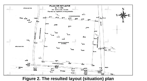
The marginal (contour) points of the plots were saved in a dwg file from AUTOCAD.
While opening the file the units of measurement were set in – m -, the precision of the
76
Figure 2. The resulted layout (situation) plan
As the measurements were performed by using the total station, the prior measurements and the actual (proper) layout were performed from the points previously established during the works carried out in order to identify the land, initially attributed when applying the laws on property. Thus, it was not necessary to post-process the measured data, the downloading of the apparatus (device) being made in “gsi” format and after that the data were imported into Autocad in order to process the layout (situation) plan.
When the layout (situation) plan was worked out and the found land limits were verified based on the documentation for the tabulation (registering) of the land, we overlapped the foundation plan (containing the centre (axes) lines of the future investment) provided by the specialized designer, by observing the spacing (distances) and location of buildings approved by the Certificate of Urban Planning and by the Building Permit.
Figure 3. Placing a polyline through (across) all the axes (lines) of the investment
It was copied in the Notepad program, in txt format (ASCII) in order to be imported (stocked) in Excel and then in the Leica Geo Office Program Coordinate Editor for being transformed (converted) in gsi format and transferred in the total station in order to be applied in the field.
Table 3
Rectangular coordinates of the layout network
Point Nr. X[m] Y[m]
102 IZ 484219.225 225949.143
101 IZ 484288.250 220020.727
77
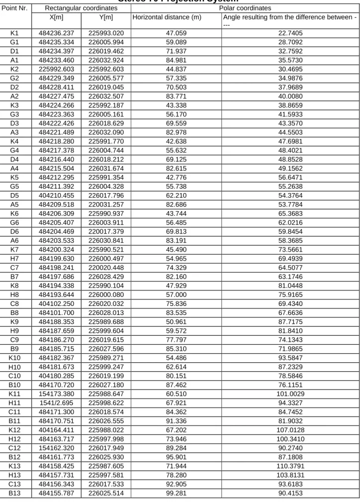
Table 4
Rectangular and polar coordinates of the foundation axes (lines) Stereo 70 Projection System
Point Nr. Rectangular coordinates Polar coordinates
X[m] Y[m] Horizontal distance (m) Angle resulting from the difference between
----
K1 484236.237 225993.020 47.059 22.7405
G1 484235.334 226005.994 59.089 28.7092
D1 484234.397 226019.462 71.937 32.7592
A1 484233.460 226032.924 84.981 35.5730
K2 225992.603 225992.603 44.837 30.4695
G2 484229.349 226005.577 57.335 34.9876
D2 484228.411 226019.045 70.503 37.9689
A2 484227.475 226032.507 83.771 40.0080
K3 484224.266 225992.187 43.338 38.8659
G3 484223.363 226005.161 56.170 41.5933
D3 484222.426 226018.629 69.559 43.3570
A3 484221.489 226032.090 82.978 44.5503
K4 484218.280 225991.770 42.638 47.6981
G4 484217.378 226004.744 55.632 48.4021
D4 484216.440 226018.212 69.125 48.8528
A4 484215.504 226031.674 82.615 49.1562
K5 484212.295 225991.354 42.776 56.6471
G5 484211.392 226004.328 55.738 55.2638
D5 404210.455 226017.796 62.210 54.3764
A5 484209.518 220031.257 82.686 53.7784
K6 484206.309 225990.937 43.744 65.3683
G6 484205.407 226003.911 56.485 62.0216
D6 484204.469 220017.379 69.813 59.8454
A6 484203.533 226030.841 83.191 58.3685
K7 484200.324 225990.521 45.490 73.5661
H7 484199.630 226000.497 54.965 69.4939
C7 484198.241 220020.448 74.329 64.5077
B7 484197.686 226028.429 82.160 63.1746
K8 484194.338 225990.104 47.929 81.0448
H8 484193.644 226000.080 57.000 75.9165
C8 404102.250 226020.032 75.836 69.4340
B8 484101.700 226028.013 83.535 67.6636
K9 484188.353 225989.688 50.961 87.7175
H9 484187.659 225999.604 59.572 81.8410
C9 484186.270 226019.615 77.797 74.1343
B9 484185.715 226027.596 85.310 71.9865
K10 484182.367 225989.271 54.486 93.5847
H10 484181.673 225999.247 62.614 87.2329
C10 404180.285 226019.199 80.151 78.5846
B10 484170.720 226027.180 87.462 76.1151
K11 154173.380 225988.647 60.510 101.0029
H11 1541/2.695 225998.622 67.921 94.3327
C11 484171.300 226018.574 84.362 84.7452
B11 484170.751 226026.555 91.336 81.9032
K12 404164.411 225988.022 67.202 107.0128
H12 484163.717 225997.998 73.946 100.3410
C12 154162.320 226017.949 89.284 90.2740
B12 484161.773 226025.930 95.901 87.1808
K13 484158.425 225987.605 71.944 110.3791
H13 484157.731 225997.581 78.280 103.8131
C13 484156.343 226017.533 92.905 93.6183
78
In order to perform the verification a second network point, net point 1001, was prepared by using the polar layout in order to verify the axes (lines) as follows:
Table 5
Polar coordinates of the foundation axes (lines)
Station Point
nr.
Horizontal distance [m] Angle resulting from the difference
between ----
101 IZ K1 61.980 17.1064
G6 89.416 27.4962
K13 135.591 35.0792
D6 84.301 46.6383
B13 132.468 53.1292
A6 84.817 56.8013
A1 55.139 60.8816
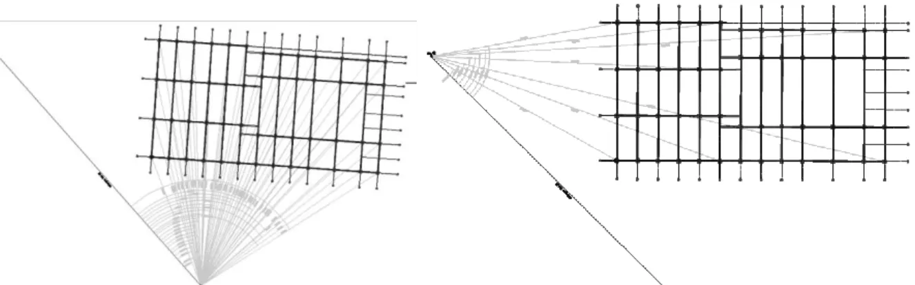
The data storage in the memory of the total station was made concurrently with the sketches of the land for the project implementation on the ground as follows:
Figure 4. Layout sketch from the 102IZ point and the layout verification from the 101IZ point
The layout survey works of the investment were made according to the Guidelines C.83 – 75 and standard STAS 9824/1,2,3 -75.
After performing the perimetric surroundings (leading marks) all the interaxes (interlines) of the buildings were materialized by using wooden pegs and nails by respecting the distances stipulated in the project, and by placing them the axes (lines) were transmitted, by nails, on the upper edge (top) of the leading mark (beacons) planks.
Given the large sizes of the investment and its grate number of axes (lines), the verification was made both by verifying the distances, alignments and by verifying any possible angular deviations in the horizontal plane of the axes (lines) bringing the corrections required. If the buildings are small, the verification may be also carried out by measuring the diagonals of the interaxes of the building that must be equal.
CONCLUSIONS
In order to carry out the engineering survey works in the field (layout, pressing on/ leveling /survey of highs, surveying) the following steps and procedures will be taken into account:
79
The ribbons and the tapes should have the length printed on them, they should not
to be broken, riveted and of course they should be verified.
The leveling poles / rods used in layout operation should be verified in terms of scale and be equipped with spherical levels for vertical lining
Before performing the layout, the planimetric position and the level-related plan of the points belonging to the support network (system) in relation to which the laying out will be performed must be verified.
The layout of the points must be carried out with extreme precision: metal chips, nails, nail stake, sign marked with a pencil or other precision elements, etc.
Any layout (procedure) must be accompanied by the verification operation, immediately after the layout points were marked. The items that have resulted from the layout should be especially verified.
Action will be taken for the conservation and protection of the layout points and of the points used for performing the layout.
During the execution, action will be taken in order to verify the position of the construction elements according to the execution project.
In case of using electronic devices for laying out distances, the measurement precision will be verified according to the standards in force, in order to comply with the permissible limits while performing the layout (process).
In order to ensure an execution as precise as possible, we must take into account all the stages and laying out procedures mentioned above.
BIBLIOGRAPHY
1. Bârliba Luminiţa Livia and collab. 2005, Topography, Solness Printing House
Timişoara;
2. Boş N., 1993. Topography, Didactic and Pedagogical Printing House, Bucharest.
3. Constantinescu I, 1999. General and Engineering Topography Course, Reprography
of Craiova University;
4. Dragomir I.P. and collab, 2001, Terrestrial (Ground) Measurements- Foundations,
Tome II, Engineering Topography. Matrix Rom Printing House, Bucharest
5. Leu I.N. and collab, 2002, Topography and Land Register. Universul Printing House,
Bucharest
6. Ursea V. and collab., 1986, Engineering Topography - Practical Works and Projects
Guide, ICB Bucharest
7. **** - Collection of Standards: Contructions tome I, 1997, Terrestrial (Ground)