Enforce transmission of unnatural power flow of series converter
with clamped multi level Neutral point converter
1Rangu Seshu Kumar,2N.Vijay Kumar
1M.Tech(Research Scholar),2Assistant Professor,Dept. of EEE in Godavari Institute of Engineering & Technology (GIET),Rajahmundry(A.P),INDIA.
Mail Id: [email protected]
Abstract: In my paper, enforcing of the unnatural power flow in
a transmission grid can be controlled by using Unified power flow control (UPFC) to sustain the maximizing power. In the UPFC the direct power is valuable control technique. The direct flow control can be used with any topology of voltage source converter. For series multi level converter non ideal transformers and load. While comparing other controllers we can obtain the better response under balanced and unbalanced conditions. Simulation and experimental results of a full three-phase model with non-ideal transformers, series multilevel converter, and load confirm minimal control delay, no overshoot, no cross coupling. In this paper, the direct power control is demonstrated in detail for a third-level neutral point clamped converter. Index Terms — Unified power-flow controller (UPFC). Direct power control, multilevel converter, sliding mode control.
I. Introduction
A unified power-flow controller (UPFC) is the most versatile of these flexible AC transmission systems (FACTS) control devices. To enhance the functionality of the ac transmission grid, flexible ac transmission systems (FACTS) support the transmission grid with power electronics. Unless active grid elements are used, the power flow will not follow the path of least impedance, moreover it is uncontrollable. These devices offer a level of control to the transmission system operator.
The major control functions of a UPFC are: (i) active power regulation; (ii) reactive power regulation; and (iii) voltage regulation. The UPFC consists of combined series and shunt devices, and the dc terminals which are connected to a common dc-link capacitor. The series device controls active power flow from the sending to the receiving end by means of adjusting the phase angle of the output voltage. On the other hand, the shunt device performs regulation of the dc-link voltage as well as control of reactive power. The UPFC realizes power flow control, stability improvement; and so on A transmission line equipped with a UPFC can control the balance of the trans-mitted power between parallel lines and, as such, can optimize the use of the transmission grid for all parallel power flows.
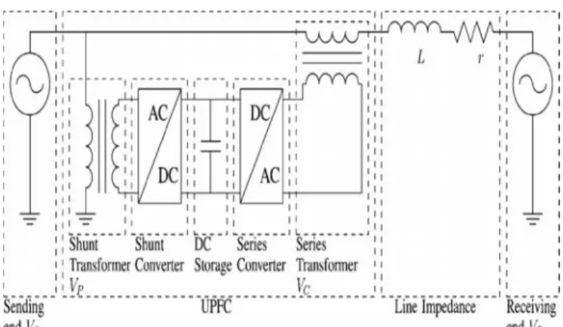
A one-wire schematic of a transmission- line system equipped with a UPFC is given in fig A UPFC is connected to the trans-mission line by coupling transformers, both with a shunt and with a series connection. The UPFC consists of two
ac/dc converters, the ac sides connected to the shunt and series connection with the transmission line, and the dc sides connected back to back. UPFCs are typically built with voltage -sourced converters, having a capacitor as (limited) dc energy storage.
Fig. 1 One-wire schematic of the transmission line with UPFC.
In an overview of the most common control structure for UPFCs is displayed below Fig. 2. An external control describes the set-points of the power system (steady state or dynamic). The internal control describes the actual power electronics and safeties of the UPFC.
The external control is typically divided into a master and middle control. The master control handles targets such as an optimal power system set point, increase of transient stability, or sub synchronous resonance dampening and delivers the middle control set points. Middle control translates these master set points into set points for the series and shunt converter. The internal controller translates these middle-level control set points into switching decisions for the power-electronic components.
Fig. 2 UPFC controller classifications and the position of the
proposed direct power controller
II. Concepts Of Facts
Power quality:
The term FACTS is used to describe electric power that drives an electrical load and the load's ability to function properly with that electric power.
The electric power industry comprises electricity generation (AC-power), electric power transmission and ultimately electricity distribution to an electricity meter located at the premises of the end user of the electric power. The electricity then moves through the wiring system of the end user until it reaches the load. The complexity of the system to move electric energy from the point of production to the point of consumption combined with variations in weather, generation, demand and other factors provide many opportunities for the quality of supply to be compromised.
Power Quality Issues:
The PQ problems are categorized as follows 1. Transients
(a) Impulsive (b) Oscillatory
2. Short-duration and Long-duration variations (a) Interruptions
(b) Sag (dip) (c) Swell
3. Voltage unbalance 4. Waveform distortion (a) DC offset
(b) Harmonics (c) Inter harmonics (d) Notching (e) Noise
5. Voltage Flicker
6. Power frequency variations.
Operating Principle Of UPFC:
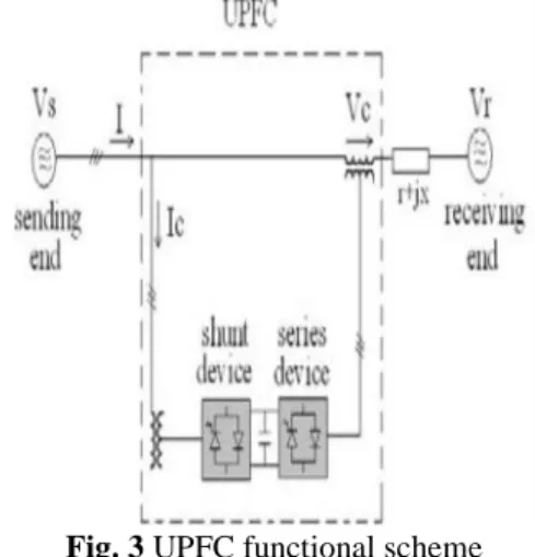
The basic components of the UPFC are two voltage source inverters (VSIs) sharing a common dc storage capacitor, and connected to the power system through coupling transformers. One VSI is connected to in shunt to the transmission system via a shunt transformer, while the other one is connected in series through a series transformer. The series inverter is controlled to inject a symmetrical three phase voltage system (VSC), of controllable magnitude and phase angle in series with the line to control active and reactive power flows on the transmission line.
A basic UPFC functional scheme is shown in figure below.
Fig. 3 UPFC functional scheme
So, this inverter will exchange active and reactive power with the line. The reactive power is electronically provided by the series inverter, and the active power is transmitted to the dc terminals. The shunt inverter is operated in such a way as to demand this dc terminal power (positive or negative) from the line keeping the voltage across the storage capacitor Vdcconstant. So, the net real power absorbed from the line by the UPFC is equal only to the losses of the inverters and their transformers. The remaining capacity of the shunt inverter can be used to exchange reactive power with the line so to provide a voltage regulation at the connection point.
Using the model of Fig.3, differential equations that describe the current isin three phases can be formulated.
Voltages are used for
notation simplicity.
The differential equations for the UPFC model are given as:
Applying the Clarke and Park transformation results in differential equations in dq space. Voltages
are introduced for notation simplicity. It is assumed that the pulsation ω of the grid is known and varies without discontinuities. Applying the Laplace transformation and with substitution between the two dq space transfer functions (2) is
obtained, where current are given in function
of voltages .
The active and reactive power of the power line is determined only by the current over the line and the sending end voltage. Without losing generality of the solution, we synchronize the Park transformation on vsa, resulting in vsq=0. Assuming relative voltage stabilityVsd(s)= vsd,VRdq(S)= VRdq , . Active and reactive power at the sending end are calculated as
Substituting (2) into (3), we receive the transfer functions, linking Ps(S), Qs(S), toVS,VR, and VC(S) . Both active and reactive power consist of an uncontrollable constant part, which is determined by power source voltages, VS,VR, and line impedance, L, r and a controllable dynamic part, determined by converter voltage VC(S), as made explicit in
Splitting in a constant uncontrollable and a dynamic controllable part results in (5) and (6).For notation simplicity VCd(S), VCq(S) , are replaced by , VCd,VCq
It is interesting to take a further look at the components of the dynamic part of the active and reactive power , , especially at the response to steps in series converter injected voltage , . Using the initial value theorem on (6), we have It is clear that only effects the derivative instantaneously, & only effects the derivative instantaneously.
It is clear that only effects the derivative
instantaneously, & only effects the derivative instantaneously.
III Multi level Converter
An inverter is an electrical device that converts direct current (DC) to alternating current (AC); the converted AC can be at any required voltage and frequency with the use of appropriate transformers, switching, and control circuits.
Cascaded H-Bridges Inverter:
A single-phase structure of an m-level cascaded inverter is illustrated in Figure Each separate dc source (SDCS) is connected to a single-phase full-bridge, or H-bridge, inverter. Each inverter level can generate three different voltage outputs, +V
dc, 0, and–Vdcby connecting the dc source to the ac output by different combinations of the four switches, S
1, S2, S3, and S4. To obtain +V
dc, switches S1and S4are turned on, whereas –Vdccan be obtained by turning on switches S
2and S3. By turning on S1 and S
2or S3and S4, the output voltage is 0. The ac outputs of each of the different full-bridge inverter levels are connected in series such that the synthesized voltage waveform is the sum of the inverter outputs. The number of output phase voltage levels m in a cascade inverter is defined by m = 2s+1, where s is the number of separate dc sources. An example phase voltage waveform for an 11-level cascaded H-bridge inverter with 5 SDCSs and 5 full bridges is shown in Figure. The phase voltage v
an= va1+ va2+ va3+ va4+ va5.
For a stepped waveform such as the one depicted in Figure with s steps, the Fourier Transform for this waveform follows
Fig: 4 Single-phase structure of a multilevel cascaded H-bridges
inverter
The magnitudes of the Fourier coefficients when normalized with respect to V
dcare as follows:
Fig.5 Output phase voltage waveform of an H-level cascade
inverter
applications as static var generation, an interface with renewable energy sources, and for battery-based applications. Three-phase cascaded inverters can be connected in wye, as shown in Figure, or in delta. Peng has demonstrated a prototype multilevel cascaded static var generator connected in parallel with the electrical system that could supply or draw reactive current from an electrical system.
Advantages:
The number of possible output voltage levels is more than twice the number of dc sources (m = 2s + 1).
The series of H-bridges makes for modularized layout and packaging. This will enable the manufacturing process to be done more quickly and cheaply.
Disadvantages:
Separate dc sources are required for each of the H-bridges. This will limit its application to products that already have multiple SDCSs readily available.
Diode-Clamped Multilevel Inverter:
The neutral point converter proposed by Nabae, Takahashi, and Akagi in 1981 was essentially a three-level diode-clamped inverter. In the 1990s several researchers published articles that have reported experimental results for four-, five-, and six-level diode-clamped converters for such uses as static VAR compensation, variable speed motor drives, and high-voltage system interconnections.
The diode clamped multilevel inverter has almost the same structure as the flying capacitor, but instead of capacitors this inverter type uses diodes as clamping devices, creating the desired output voltage. The voltage across each capacitor is defined as VDC/m−1 , m being the number of levels and m−1 the
amount of capacitors needed. So, for a two-level inverter the voltage is VDC and for that case one capacitor is used. For a three-level inverter the voltage is VDC/2 and therefore is in need of two capacitors. This specific design makes it possible to increase the number of levels just by increasing the amount of capacitors. In this context the terminology “neutral point clamped” is often used. It describes the neutral point between two capacitors connected across the DC-bus adding an extra level to the system. If m is an even number, the neutral point is not utilized, so then it is usually called a multiple point clamped converter.
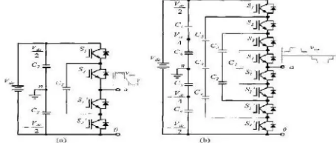
Fig. 6 A Diode Clamped converter for a (a) three-level inverter
(one phase leg) and for (b) five-level inverter (one phase-leg)
Experience show that higher levels than the three-level converter causes voltage balancing problems, so it is common to use the three-level inverter , but there are studies demonstrating SVPWMs with self balancing systems.
In the fig( b)there are five possible voltage outputs (Van): VDC/2, VDC/4, 0, VDC/4 and VDC/2 and they operate as seen in below Table.
Table.1 Duty cycle for the switches in one phase leg (five-level
inverter)
Reaching higher levels decreases the lower harmonics and the need for filters, but at the same time it magnifies the need for clamping diodes. Advantages with the diode-clamped inverter are the high efficiency. This because all the devices are switched at the fundamental frequency. The diode-clamped inverter also has a easy reactive power control application, but has difficulties controlling the real power for the individual converters.
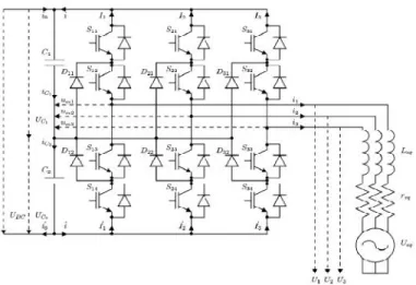
Three-Level Neutral Point Clamped Converter:
A schematic of a three-level neutral point clamped converter is given in Figure. Each leg of the converter consists of four switching components SK1,SK2,SK3, and two diodes and DK1, andDk2 .The diodes DK1,DK2 clamp the voltages of the
Van Switches (ON)
VDC/2 S1-S4
VDC/4 S2-S4 and S1'
0 S3,S4,S1',S2'
-VDC/4 S4,S1'-S3'
connections between SK1,SK2 ,andSK3,SK4 , respectively, to the neutral point, between capacitorsC1,C2.There are three possible switching combinations for each leg K, thus three voltages Umk. The three levels for voltages Umk produce five different converter phase-output voltages .The upper and lower leg currents IK,IK, or their respective sum i, i,can be described in function of the output line currents iK. The system state variables are the line currents i1,i2,i3, and the capacitor voltages UC1,UC2 [32]. is system has the dc-bus current i0and the equivalent load source voltages Ueqk as inputs. Under the assumption that the converter output voltages UKare connected to an req, Leqsystem with a sinusoidal voltage source UeqWith isolated neutral,
Fig. 7 Three level neutral point clamp converter
As in Fig, we can write the equations for the three-phase currents i1, i2,i3as in
The capacitor voltages UC1,UC2,are infl0nced by the sum of the upper and lower leg currents i,i,and the input current i0,i0,as in
From the restrictions on the states of the switching devices in each leg of the converter, we can define the ternary variableϒk(t), representing the switching state of the entire leg, as
To simplify notation, combinations of this variable,ϒk, Ґ and are introduced With this variableϒk(t) , and the derived variable and straightforward equations can be found for the description of the other variables in the system. Combining the equations of the system dynamics (8) and (9),
the complete system equation is (14) [32], whereϒ123,
Ί1(ϒ123), Ί2(ϒ123), are aiding functions describing the precise dynamics in function of the switching state. It is important to realize that this system equation is not constant, nor continuous.
Fig. 8Vector arrangement in five levels in α,β, forthree-level three-phase converter.
(a) Five levels in, α,ϒα. (b) Five levels in β,ϒβ
Flying Capacitor Multilevel Inverter:
The flying capacitor is also known as the capacitor clamped inverter, because of its independent capacitors clamping the voltage to one capacitor voltage level . The structure of the system is formed as a ladder and the voltage of each capacitor is different from the other. When the voltage between two side by side placed capacitors increases, it transmits the size of the voltage steps in the output waveform.
One advantage of the flying-capacitor-based inverter is that it has redundancies for inner voltage levels for the multilevel flying capacitor is static VAR generation. The main advantages and disadvantages of multilevel flying capacitor converters are as follows.
Fig. 9 Circuit of a Flying Capacitor (a) two-level converter for
one phase leg (b) three-level converter for one phase leg Advantages:
Phase redundancies are available for balancing the voltage levels of the capacitors.
Real and reactive power flow can be controlled.
The large number of capacitors enables the inverter to ride through short duration outages and deep voltage sags.
Disadvantages:
Control is complicated to track the voltage levels for all of the capacitors. Also, precharging all of the capacitors to the same voltage level and startup are complex.
Switching utilization and efficiency are poor for real power transmission.
The large numbers of capacitors are both more expensive and bulky than clamping diodes in multilevel diode-clamped converters. Packaging is also more difficult in inverters with a high number of levels.
IV Direct Power Control
Direct power control must ensure that the sending end power PS(t),qS(t) , follows power references PSref(t),qSref(t) , .Defining the strong relative degree of the controlled output PS(t),qS(t) , as the minimum i th-order time derivative di(PS(t))/dti, di(qS(t))/dti,, that contains a nonzero explicit function of the control vector VC, a suitable sliding surface is a linear combination of the phase canonical state variable errors.For PS(t), and qS(t) ,i=1,then
In (17),K is a strictly positive constant; therefore, the only possibility for the system to uphold the surface equations Sd(t) ,Sq(t)=0, is having the real power PS(t),qS(t), follow the references, PSref(t), qSref(t). A control law that enforces the system to stay on these surfaces, or move toward them at all times.
Where Sd(s) ,Sq(s), are governed by system dynamics involved (6). To uphold (18), the inverter has to appropriately change the sign of the derivatives Sd(t) ,Sq(t) .Using the results of the initial value theorem on the derivative of the sending end power in (7), the following equation can be developed:
From (19), it can be concluded that to instantaneously influence, Sd(t),VCd(t) should be used. Similarly, for Sq(t) , it is done best by VCq(t) . It is also clear from (19) that impulse or step changes in∆ PSref(t), ∆qSref(t) , cannot be followed instantaneously, yet ramps in ∆PSref(t), ∆qSref(t) , can be followed, providing their rate of change is less than (max (VCd)/L), VSd(max (VCq)/L), VSd , and the combination cannot exceed
From (21), several important conclusions can be drawn. The control can only handle limited steps or ramps of decaying derivative in references,∆ PSref(t),∆qSref(t) . Also, a clear limit exists to the controllable reference steps, limited by the maximum UPFC series output voltage amplitude, VCmaxas
In the selection Power to desired change in λ of Fig., the implementation of 19 exists. To select a physical voltage vector, this decision process is transformed to the αβ domain, remaining with requested changes of the UPFC series output voltage in αβ to the output voltage vector. To limit the switching frequency, the decision is suppressed until the system state crosses a parallel surface at a certain distance from the direct power control surfaces∆S . Note that this requested change is not expressed in a numeric value of the requested change, but as the direction of change (in this case, a ternary variable, indicating increase +1 , no change 0, decrease -1). Depending on the currently used output vector and the requested change in αβ, an appropriate next vector can be selected. This concludes the converter topology independent part of the controller.
In Fig., in the selection Desired change in λ to output
Voltage, for a three-level NPC converter, the voltage vector selection is displayed. DPC demands increasing or decreasing the output voltage vector in the α and β direction. Based on the currently applied vector and this demand, the next vector is selected. This is simplified to selection of the voltage vector levels λα, λβ . In the cases that vectors coincide, an extra
criterium is needed to unambiguously select a set of switching
Fig. 10 Overview of control algorithm
state variables ,ϒ1,ϒ2,ϒ3 . Even though the voltage vectors may realize the same phase voltages U1,U2,U3,the precise switching state ϒ1,ϒ2,ϒ3 , also determines whether energy is drawn or injected from or into capacitors UC1and UC2
To maintain voltage balance UC1-UC2=0, (23) must be upheld at all times. This is displayed in Fig. 6 in selection Capacitor voltage balance control. Depending on the sign of the voltage unbalance UC1-UC2 and output power P, the voltage vector can be selected so that is upheld. Vector selection, in function of demand for change of the voltage vector in αβ , dimension and capacitor voltage unbalance UC1-UC2 is given in Table II(a) and (b). To limit the output frequency, the size of the voltage unbalance has to reach a certain level∆UC before it is addressed. In this application, it is enforced by a relay system. The last degree of freedom is within the selection of the null vector 1, 14, 27. They have the same effect on the output voltage U and capacitor voltage imbalance UC1-UC2. To minimize the switching losses, the null vector could be chosen within least switching distance from the previous vector. As such, any order from a higher controller to change the output voltage U in αβ is translated unambiguously into a voltage-output vector. This voltage vector selection method is well covered, including the necessary balancing of the capacitor voltages.
V Simulation Results
The controller is demonstrated in simulation and in experimental results.
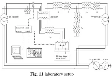
Fig. 11 laboratory setup
Simulation: The simulation is based on a full three-phase model of the UPFC and the power lines constructed with Matlab Simulink. It is performed on a balanced model of the experimental setup. It contains a model of the converter based on the dynamic equations and control laws. UPFC shunt converter and dc capacitor dynamics are included in the system model.
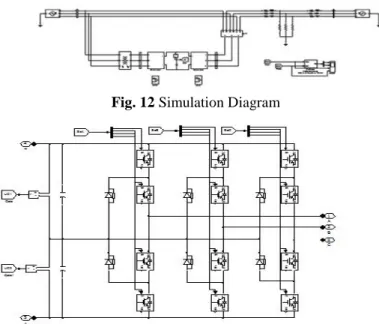
Mainly The simulation diagram has four stages.(1) sending end (2) UPFC (3) line impedance (4) receiving end.
Fig. 12 Simulation Diagram
Fig. 13 Simulation diagram for shunt converter:
The shunt converter is set to control the total dc voltage level of the converter dc bus.
Fig. 14 Simulation diagram for series converter
No reactive power transfer between the shunt converter and the sending end bus is set; the sending and receiving end are simulated as infinite bus.
The transformers are modeled as saturable transformers. In the first set of results, the DPC method is put to demonstrate
power-flow control. In a second set, the DPC method is compared in simulation to two other controllers in normal and unbalanced conditions, to demonstrate the superior performance of the DPC method.
Fig. 15 DPC power-flow control
In simulation PSref,qSref take values of 0 to 0.316 p.u. and change stepwise. It should be noted that the references, do not represent a realistic reference profile. An overview of 2.5 s of the closed-loop controlled output in Fig. 16 demonstrates that the system can handle any combination of sending end power references PSref, qSref and reference changes.
Fig. 16 Closed-loop Controlled Output
UPFC series converter controlling power flow under balanced condition Taking the of Psref,qSref Are step wise change, The time is 2.5s the closed-loop controlled output in Fig. demonstrates that the system can handle any combination of sending end power references PSref, qSref and reference changes
Fig. 17 Stepwise change in active & reactive power flow.
no cross coupling, no steady-state error, and a fast rising and settling time.
UPFC series converter controlling power flow, comparison between DPC-ADC:
.Fig. 18 UPFC Series converter controlling power flow Comparison of DPC-ADC
DPC Compared to Other Controllers:
The same simulation model is used as in the previous test. The DPC will be compared with two other controllers: advanced dynamic control (ADC) and dynamic inverse control (DIC).Both are middle-level controllers, with a clearly described design methodology. The controllers are designed as specified in their sources, and the parameters can be found in the Appendix. To create fair comparison conditions, the converter control is implemented by a sliding mode controller for the three level converter with the same switching frequency, switching table, and relay widths as the one incorporated in the DPC.
1) Balanced Condition: The three controllers are compared under equal conditions of the previous simulation, which are completely balanced. It can be seen from Fig that the DPC demonstrates the smallest perturbation from the set point in steady-state conditions. ADC demonstrates low-order harmonics and steady-state error, while DIC demonstrates serious low-order harmonics. From Fig which is a zoom of Fig it can be seen that the DIC and ADC have a faster response to a step, but present more overshoot, and have a longer settling time. Overall, the DPC presents better performance under balanced conditions, both in steady state and dynamically.
2) Unbalanced Voltage Sag: The controllers are compared during single line-to-line voltage sag, with 70% of nominal voltage remaining. Fig shows that the DPC is fairly indifferent, whereas DIC and ADC demonstrate an increase in their low-order harmonics. DPC has the best response to unbalanced voltage conditions.
Conclusion
The enforced transmission of unnatural power flow of series converter with clamped multi level Neutral point converter demonstrated the technique has been applied to a three-level NPC converter. The DPC technique was applied to a UPFC to control the power flow on a transmission line. The main advantage of the control techniques are fast dynamic control behavior with no cross coupling or overshoot, with a simple controller, independent of nodal voltage changes. The
controller was compared to two other controllers under balanced and unbalanced conditions, and demonstrated better performance, with shorter settling times, no overshoot, and indifference to voltage unbalance. It is readily adaptable to other converter types than the three-level converter demonstrated in this paper. The realization was demonstrated by simulation and experimental results on a scaled model of a transmission line. I conclude that direct power control is an effective method that can be used with UPFC.
References
[1] J. Monteiro, J. Silva, S. Pinto, and J. Palma, “Matrix converter - based unified power - flow controllers: Advanced direct power controlmethod,” IEEETrans. Power Del., vol. 26, no. 1, pp. 420–430, Jan. 2011.
[2] Jan Verveckken, Fernando Silva, Dionísio Barros, Johan Driesen - Senior Members, IEEE. “Direct Power Control of Series Converter of Unified Power-Flow Controller With Three-Level Neutral Point Clamped Converter” IEEE TRANSACTIONS ON POWER DELIVERY, VOL. 27, NO. 4, OCTOBER 2012.
[3] S. Jiang, A. Gole, U. Annakkage, and D. Jacobson, “Damping performance analysis of ipfc and upfc controllers using validated small-signalmodels,” IEEE Trans. Power Del., vol. 26, no. 1, pp. 446–454, Jan. 2011.
[4] M. Zarghami,M. Crow, J. Sarangapani, Y. Liu, and S.Atcitty, “A novel approach to interarea oscillation damping by unified power flow controllers
utilizing ultracapacitors,” IEEE Trans. Power Syst.,vol. 25, no. 1, pp. 404–412, Feb. 2010.
[5] A. Rajabi-Ghahnavieh, M. Fotuhi-Firuzabad,M. Shahidehpour, and R. Feuillet, “Upfc for enhancing power system reliability,” IEEE Trans.Power Del., vol. 25, no. 4, pp. 2881–2890, Oct. 2010.
[6] X. Jiang, J. Chow, A.-A. Edris, B. Fardanesh, and E. Uzunovic, “Transfer path stability enhancement by voltage -sourced converter-based facts controllers,” IEEE Trans. Power Del., vol. 25, no. 2, pp. 1019–1025, Apr. 2010.
[7]J. Guo, M. Crow, and J. Sarangapani, “An improved upfc control foroscillation damping,” IEEE Trans. Power Syst., vol. 24, no. 1, pp. 88–296, Feb. 2009.
[8]S. Ray and G. Venayagamoorthy, “Wide-area signal-based optimal neuro controller for a upfc,” IEEE Trans.Power Del., vol. 23, no. 3, pp. 1597–1605, Jul. 2008.
[9] S. Venkateschwarlu, B. P. Muni, A. D. Rajkumar, and J. Praveen,“Direct power control strategies for multilevel inverter based custompower devices,” Int. J. Elect. Syst. Sci. Eng., vol. 1, no. 2, pp. 94–102,
2008.