R
AILROAD
&
C
O
.
™
TrainProgrammer
™
Version 8
Users Guide
R
AILROAD
&
C
O
.
™
TrainProgrammer
™
Version 8
Users Guide
Contact: Freiwald Software Kreuzberg 16 B
D-85658 Egmating, Germany e-mail: [email protected] http://www.freiwald.com All rights reserved.
Table of Contents
About this Document ... 5
RAILROAD &CO. TrainProgrammer™ Users Guide ... 5
Help Menu ... 6
Quick Start - Step 1: Installation and Program Start ... 8
Installation ... 8
Program Start ... 9
Quick Start - Step 2: Reading the digital Address of a Locomotive ... 13
Quick Start - Step 3: Changing the digital Address of a Locomotive ... 18
Quick Start - Step 4: Changing a short Address to a long Address ... 20
1 Introduction ... 24
1.1 Overview ... 24
Supported digital Systems ... 24
Use ... 25
1.2 Fundamentals of Use ... 26
The Overall Principle ... 26
Decoders and Devices ... 26
Configuration Options and Decoder Configurations ... 26
Decoder Database ... 27
File Handling ... 27
User Interface Design ... 27
Window Handling ... 28
Customization of Menus, Tool Bars and Keyboard Accelerators ... 28
Printing ... 29
2 Working with the Decoder Window ... 31
2.1 General ... 31
2.2 Selecting the right Decoder Configuration ... 32
Freeware Configuration ... 32
Standard Configuration ... 33
Specialized Configurations ... 34
2.3 Programming the Decoder ... 34
2.5 Mapping Function Keys to Output Locations ... 40
2.6 Custom Editors ... 41
3 The Test Panel ... 42
4 The Direct Programmer ... 43
5 Run-In of Locomotives ... 44
6 Use of a Roller Test Bench ... 46
7 The Decoder Database ... 48
7.1 Editing of Decoder Configurations ... 49
Configuration Properties ... 51 7.2 Configuration Options ... 51 Folder ... 51 Number ... 52 Check Box ... 52 Structure ... 53 Formula ... 53
Overview of Option Types ... 54
Properties of Configuration Options ... 55
Reference ... 55
Indexed Options ... 56
7.3 Multilingualism, Derivation, Templates ... 57
Multilingual Decoder Configurations ... 57
Derivation ... 57
Templates ... 58
Appendix: Troubleshooting ... 59
Problems during Reading and Writing of Decoder Values ... 59
Compatibility problems ... 59
About this Document
RAILROAD &CO. is the leading product line of computer programs for digitally or conventionally controlled model railroads. It contains the following members:
• TrainController™ is the world's leading software for model railroad computer control.
• TrainProgrammer™ is the program, which makes programming of DCC decoders as simple as a few clicks with your mouse.
• +Net™ is a module, that allows you to control your layout with a network of several computers running TrainController™.
• +4DSound™ is a module, that recreates realistic spatial sound effects for each model railroad layout controlled by TrainController™ without the need to install on-board sound into each decoder.
• +SmartHand™ is the world's premium handheld railroad control system designed for computer controlled model railroads.
RAILROAD &CO. TrainProgrammer™ Users Guide
An overview of the basic concepts of TrainProgrammer ™ is provided in this Users Guide. By reading this document one can obtain information about the many features of the product. Additionally you are provided with background information necessary for digital decoder programming with TrainProgrammer™.
The document is divided into two parts. Part I provides a quick start tutorial for users, who are in a hurry and are in a fever to start quickly. Part II explains the fundamentals of use.
Details of usage are mentioned only if they are necessary to understand the related is-sues, or to point to important features of the program. If you want to know in detail, how specific functions are to be used, refer to the Help menu of TrainProgrammer™, please.
Several sections or paragraphs show additional markings for novice or advanced read-ers or to indicate important notes. The markings and their meaning are:
Basic content. Novice readers should focus on these parts.
Extended content for advanced users. Novice readers should ignore these parts in the beginning.
Important note.
Help Menu
The help menu installed with TrainProgrammer™ contains detailed reference infor-mation necessary for using the program. All menus, dialogs and options are completely described and can be referred to in case of questions or problems.
Please note: no document is complete without the other. If you want to know, what a certain term means or what a certain function does, refer to this Users Guide, please. If you want to know, how a certain object is to be edited or how a specific function is to be executed, call the help menu.
B
X
!
Part I
Quick Start
Quick Start - Step 1:
Installation and Program Start
You have obtained TrainProgrammer™ to conveniently program the decoders and other devices of your digitally controlled model railroad with your computer. It is easily understood, if you are eager to use the program as soon as possible. If you are in a hurry about starting without reading the complete Users Guide first, you can also run through the following quick start tutorial about TrainProgrammer™.
Detailed explanations about the concepts, that are the fundamentals of the following, can be found in Part II of this document. It is strongly recommended to study the con-tents of this part prior to working seriously with TrainProgrammer™.
Now let us start:
Installation
The installation file of TrainProgrammer™, its name is TPSETUP.EXE, can be downloaded from the download area of the Internet home page of the software
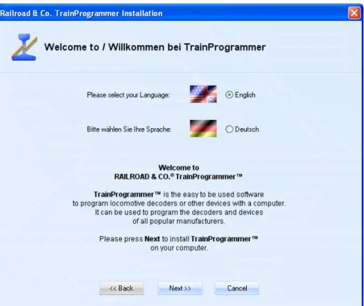
After starting TPSETUP.EXE a self-explaining window is displayed, that guides you through the steps, that are necessary to install TrainProgrammer™ on your computer.
Diagram 1: TrainProgrammer™ Setup Screen
Ensure, that you select the right language, because the selected language will also ap-pear later, when running TrainProgrammer™.
Before you start TrainProgrammer™ you should connect your digital system, with which you are controlling your model railroad, to the computer. Please refer to the in-structions provided by the manufacturer of your digital system, how this is done.
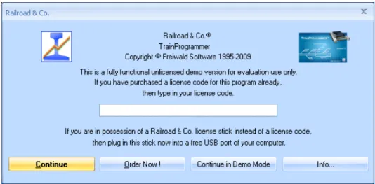
Diagram 2: License Inquiry
After start of the program the software first inquires your license key. Do not be con-cerned, if you are not yet in possession of such key. Press Continue unlicensed, if you want to try the software before buying it.
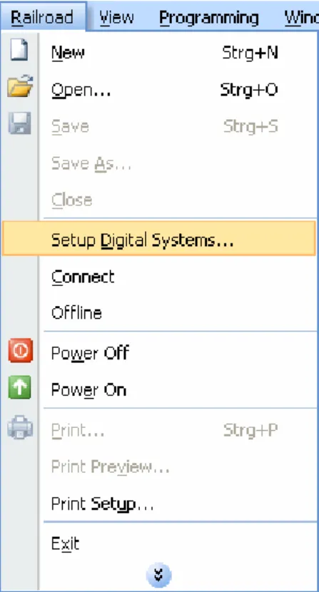
In the next step the connected digital system is to be configured. Call the Setup Digital Systems command of the Railroad menu:
Diagram 3: Railroad menu
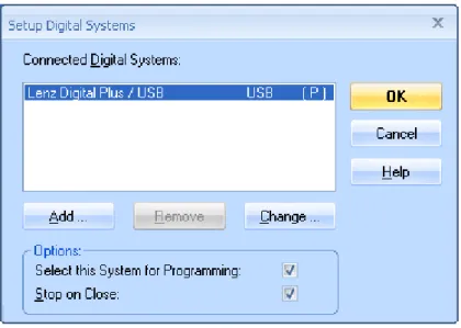
Diagram 4: Setup Digital Systems dialog
If your digital system and/or the USB or serial port of your computer, to which your digital system is connected, is not displayed accordingly, press Change to select the right settings.
In order to test, whether the connection to the digital system is properly established, play around a little bit with the Power Off and Power On command of the Railroad
menu. These commands stop or start your digital system, respectively. Your digital sys-tem should respond accordingly to these commands. If your digital syssys-tem does not re-spond or if there are even some error messages, then do not proceed any further, until this problem is resolved. In case of problems in this area, check very thoroughly, that the digital system is properly connected to the computer according to the instructions of the manufacturer.
Quick Start - Step 2:
Reading the digital Address of a Locomotive
The following steps of the tutorial require a locomotive with a NMRA DCC compatible locomotive decoder.
First put such locomotive onto the programming track and try to read the address pro-grammed into the decoder with your digital system. It is certainly not necessary to do this manual read always when you work with TrainProgrammer™, but for this tutori-al this step is recommended to verify, that the digittutori-al system, the locomotive and the de-coder are correctly working. Do not proceed until you have been able to successfully read the address from the decoder with your digital system.
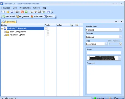
After Step 1 the screen display of TrainProgrammer™ should look as follows:
Diagram 5: TrainProgrammer™ initial screen
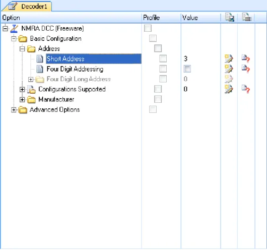
Press to the ‘+’ marking left of the entry Basic Configuration in the Option column and then to the same marking left of the entry Address.
These options should be expanded now like expanded folder entries in the File Explorer of the Microsoft Windows system.
Diagram 6: Selecting a Configuration Option
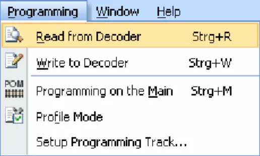
Now select the entry Short Address and call the Read from Decoder command of the
Diagram 7: Reading a Configuration Option
If everything is installed correctly then the address programmed into the decoder will appear in the Value column.
Diagram 8: Display of a read Value
In our example the address programmed into the decoder is ‘10’. In your case another address will probably appear. It should be the same value, however, as previously read with the digital system.
Quick Start - Step 3:
Changing the digital Address of a Locomotive
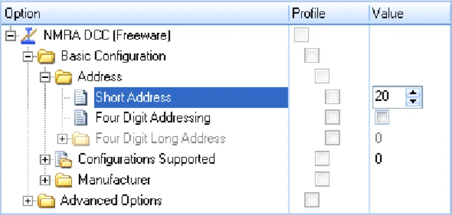
Now we want to program another address into the decoder. Instead of ‘10’ (or the cur-rently displayed value) we want to set the address of the locomotive to ‘20’.
Click once with the left mouse button to the value of the short address in the Value col-umn. The value becomes editable and can be changed to ‘20’:
Diagram 9: Changing the value of a Configuration Option
Now commit the changed value by clicking with the left mouse button somewhere on the computer screen.
Ensure, that the entry Short Address is still selected and call the Write to Decoder
If everything is installed correctly then the address ‘20’ will now be written into the de-coder. You can verify this by repeating the steps of Step 2 of this tutorial or by reading the address with your digital system.
Quick Start - Step 4:
Changing a short Address to a long Address
Now we want to program a long address, e.g. ‘2365’ into the decoder. Experienced us-ers know, that doing this with the digital system requires complex calculation of two decoder values (CV 17 and CV 18) as well as a lot of keystrokes for writing of a least 3 decoder values (CV17, CV18, CV29).
With TrainProgrammer™ such procedures are much more convenient and effective and require just a few mouse clicks.
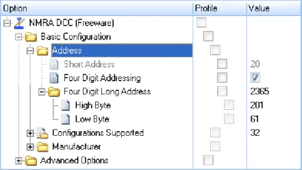
At first set a tick mark in the Value column right of the entry Four Digit Addressing. Then expand the option Four Digit Long Address. Change the current value ‘0’ right of Four Digit Long Address to ‘2365’. The screen display should look as follows now:
Diagram 11: Changing the long Address of a Decoder
The options of a decoder are arranged and viewed in TrainProgrammer™ like the files and folders in the File Explorer of Microsoft Windows. Some options can ‘con-tain’ other options (like folders containing files or other folders). The Address option, for example, contains all options and CVs, that are relevant for the address of a decod-er, among others CV1, CV17, CV18 and that bit of CV29, that controls, whether the long or short address is valid. By selecting an option, that ‘contains’ other options it is possible to read or write all contained options in one step. By selecting the Address op-tion we are able to write all opop-tions, that specify the long address, to the decoder in one step. By selecting the topmost option in the Option column we would be even able to read or write all options of the decoder in one single step.
This feature is one of the keys to make programming of decoders with
Part II
Fundamentals
1
Introduction
1.1
Overview
TrainProgrammer™ is a system for convenient and effective programming of decod-ers or devices for digital control of model railroads with a Pdecod-ersonal Computer running Microsoft Windows 8.x, Windows 7, Vista or XP.
TrainProgrammer™ can deal with decoders or devices, that support at least one of the following programming methods:
• NMRA DCC direct mode
• NMRA DCC paged mode
• NMRA DCC register mode
• Loconet Option Switch (OPSW) programming
• programming of Selectrix compatible locomotive decoders
TrainProgrammer™ is easy to use. It provides an intuitive and quickly to learn graph-ical user interface and the ease of point & click to read and write the settings of your decoders. Many decoder information like speed tables or function setups are displayed graphically and can be read, drawn and written with a few mouse clicks. The decoder information can be printed or saved on your computer. In this way the same speed table, for example, can be loaded into several decoders.
If supported by the connected digital system it is also possible to program decoders on the main track. This means that you can program decoders without having to put the lo-comotive on a separate programming track. This method is also known as “Operations Mode Programming” or “Programming on Main Track”.
TrainProgrammer™ is being delivered with a decoder-database, that contains the configurations of frequently used decoder types. It is possible to create new
• Lenz Digital Plus
• Digitrax LocoNet
• NCE
• Roco Z21, z21, Multizentrale Pro, Interface 10785
• Maerklin Central Station 2
• Uhlenbrock Intellibox, Intellibox 2, IB Basic, IB COM
• Fleischmann Z21, z21, Twin Center, Multizentrale Pro
• Tams
• Trix Selectrix
• Rautenhaus Digital (SLX and RMX)
• Muet Digirail
• D&H / MTTM Future-Central-Control
• Massoth
• Zimo
RAILROAD &CO. supports use of other applications at the same time sharing the same connections. If you have installed TrainProgrammer™ together with other RAILROAD &CO. applications, then the same configuration of digital systems can be used by all RAILROAD &CO. applications at the same time without the need to specify the type of systems or the connecting ports again. Programming of decoders is only possible with one of these connected digital systems at a time, though. The configuration of connect-ed digital systems may contain a digital system not listconnect-ed here, which is usconnect-ed by another
RAILROAD &CO. application. In this case this particular system cannot be selected for decoder programming.
TrainProgrammer™ also supports an offline mode, which allows trial operation with-out a connection to a real model railroad.
Use
TrainProgrammer™ is easy to use. It provides an easily learned, intuitive, graphical user interface that is developed according to the following guidelines:
1.2
Fundamentals of Use
The Overall Principle
The concept of TrainProgrammer™ is intended to support convenient and effective programming of decoder configurations.
The options used for programming are arranged on the computer screen in a hierar-chical structure like the folders and files of the Microsoft Windows operating systems. Options, that belong together, are grouped together. All options, that belong together, for example all options, that describe the speed and running characteristics of a decoder, can be read from or written to the decoder in one step.
Decoders and Devices
A decoder is a piece of equipment, that is usually used to control the items found on a model railroad such as locomotives, turnouts, signals, feedback sensors etc. A device is a piece of equipment, that is used to control decoders or other devices of a digitally con-trolled model railroad such as central units, handheld controls, control panels, interfac-es, boosters, reversing loop controllers, etc. In this document the term decoder is often used as synonym for device, too.
Configuration Options and Decoder Configurations
A configuration option describes an aspect of the settings of a decoder or a group of such aspects. A DCC configuration variable, for example, may be associated with one or more configuration options (for example DCC CV1, which may be associated with a configuration option called “Short Address”). A configuration option is distinguished by several properties, among others its name, a short explanation of its meaning, al-lowed content, etc. Configuration options can be grouped together according to their meaning. In case of a loco decoder, for example, the options, that control the speed of the loco are usually grouped together and separated from the options, that control the auxiliary functions of the decoder.
Please do not mistake decoder configurations for decoders. A decoder configuration contains information about one or more types of decoders. A decoder is a piece of equipment used to control your model railroad, e.g. the particular decoder, that is in-stalled in a certain steam locomotive.
Decoder Database
A decoder database is a collection of one or more decoder configurations.
TrainProgrammer™ is delivered with a default decoder database, that contains the configurations of frequently used decoder types. With TrainProgrammer™ it is also possible, to create your own decoder configurations, to customise existing configura-tions or to delete not needed configuraconfigura-tions from the database. It is also possible to add decoder configurations created by others, e.g. the manufacturer of the decoder, to your
own database. In the “goody box” of our Internet web site
download, that contains more than 400 decoder configurations of popular decoders (courtesy of JMRI). Also ask the manufacturer of your decoder for configurations, that are not yet contained in the database!
File Handling
The complete data, that belongs to one decoder or device is stored in one single file on the hard disk on your computer. This file is called decoder file. In the most common case, that the decoder belongs to a locomotive, one can also visualise the decoder file as the file, that contains the data of one locomotive. You can create as many decoder files as you like – for example a separate file for each locomotive in your collection. The decoder file contains all values stored in the physical options (CVs) of your decod-er, an optional name and image (e.g. the name and image of the locomotive, where the decoder is installed), an optional commenting text and other information.
Decoder files are created, opened and stored through the Railroad menu of the soft-ware.
This begins with the overall layout of the user interface. The user interface can be dis-played by applying different visual styles. Among others the following styles are avail-able:
• Several Office 2007 styles
• Visual Studio 2008 and 2005
• Native XP
• Office 2003
• Classic Office 2000
Feel free to select the style, that fits best your personal taste.
Window Handling
The information, that belongs to a decoder, and that is stored in one file (see above) is displayed in one window, the decoder window. In the most common case, that the de-coder belongs to a locomotive, one can also visualise the dede-coder window as the dis-play of all data, that belongs to one locomotive. You can open as many decoder win-dows as you like at the same time.
Decoder windows and opened decoder files are associated with each other. Each decoder window can appear in one of the following states:
• Docked to one of the borders of the main window.
• Docked to another decoder window.
• Floating at any location on the computer screen; individually or grouped/docked to-gether with other windows.
• Tabbed with other windows – as one of several tabbed documents in the background of the main window or together with other windows in a floating or docked frame.
• Auto-Hidden while not active with quick access via a button on any side of the main window.
menu and tool bar symbols for commands, that do not have a symbol associated with it by default, or to change existing icons with a built-in icon editor.
It is furthermore possible to display all menu and toolbar icons in large size.
Keyboard accelerators can be changed. It is also possible to assign keyboard accelera-tors to commands, that do not have a keyboard shortcut associated with it by default.
Printing
The information, that is stored in a decoder file, can be printed in a clearly arranged manner. TrainProgrammer™ will print the general properties associated with a de-coder (e.g. name and image) as well as a table of all configuration options. In this way you can create your own collection of printed data sheets for your decoders and devices.
2
Working with the Decoder Window
2.1
General
TrainProgrammer™ displays all information, that belongs to a decoder, in the decod-er window. If the decoder belongs to a locomotive, one can also visualise the decoder window as the display of all data belonging to one locomotive.
It is possible to open several decoder windows at the same time.
Diagram 13: Decoder Window
The lower right part of the decoder window may change according to the currently se-lected configuration option. By default this part shows controls to enter general data of the decoder, for example the name and image of the locomotive, which the decoder is installed in. This area of the decoder window may also show special editors for speed table editing or configuration of function maps.
2.2
Selecting the right Decoder Configuration
A decoder configuration is a set of all configuration options, that describe a particular type of decoder or device.
There are specialised decoder configurations, that describe just one specific type of de-coder (e.g. a certain locomotive dede-coder brand of a certain manufacturer). There are al-so general decoder configurations, that describe common properties of a plurality of similar decoders (e.g. a configuration, that describes common settings of NMRA DCC compatible locomotive decoders).
Decoder configurations do not only contain configuration options. Additionally they contain information, how these options shall be arranged in the explorer window, how these options shall be displayed on the computer screen and how these options shall be edited. In this way a decoder configuration also describes the user interface for interac-tion with the particular opinterac-tions of the configurainterac-tion and the values stored in the decod-er.
Decoder configurations are distinguished by the name of the manufacturer and the list name of the decoder. Some general configurations are listed with the manufacturer name “Standard”.
Freeware Configuration
The is a configuration, that can be used for almost all locomotive decoders. It contains the options required to change the address of the decoder, some basic configuration op-tions and to read manufacturer and version information from the decoder, if any.
All other configurations only support reading of the supported options from the decod-er, if no license of TrainProgrammer™ is available. Writing of decoder values with other configurations than the freeware configuration requires a valid license.
The freeware configuration is listed in the default database of TrainProgrammer™
with the manufacturer name “Standard”.
Standard Configuration
The is a configuration, that can be used for almost all NMRA DCC compatible loco-motive decoders. It contains the most commonly used configuration options.
This configuration can be used to change and view the address of a decoder, common speed and running characteristics, speed tables, function mappings and other common configuration settings.
Users, especially those which are novice in decoder programming, should preferably use the standard decoder configuration. If in doubt, which configuration to use for a particular decoder, consider to try first, whether the standard configuration doesn’t do the job already.
The standard configuration provides a user friendly, intuitive and standardised user interface for access to the most common configuration options of the majority of all NMRA DCC compatible locomotive decoders.
One aspect of the standard configuration has to be kept in mind, however: unlike those specialised decoder configurations, which are customised to the specific characteristics of a certain decoder type, the standard configuration does not take into account any spe-cific limitations with regard to value ranges and uses default or common value ranges instead. The value range of DCC CV1, “Short Address”, for example, is usually 1 to 127. If the address of a certain decoder type must not exceed 99, then this specific limi-tation of this decoder is not taken into account by the standard configuration. Before writing any value into your decoder you are responsible to ensure, e.g. by referring to the manual of the decoder, that the value to be written is within the permitted range. This does not only, but especially apply to the standard configuration. Usually you will not encounter any problems, though the supplier of this program shall not be liable to
B
!
!
The above statement should therefore be mainly understood to discharge the supplier of this program from liability.
Specialized Configurations
Specialised configurations are customized to a certain type of decoder. Usually they contain the complete set of configuration options supported by this decoder as well as their value ranges.
Experienced users and users, who want to adjust specific characteristics of their decod-er, which are not covered by the standard configuration, can use these configurations.
TrainProgrammer™ is delivered with a default decoder database, that contains a number of specialized configurations for frequently used decoder types. The “goody box” of our Internet web site (www.freiwald.com/pages/goody.htm) provides an addi-tional decoder database with more than 400 specialized decoder configurations of popu-lar decoders (courtesy of JMRI).
2.3
Programming the Decoder
The most important tool to read configuration values from the decoder or to write val-ues into the decoder is the explorer window in the left part of the decoder window.
X
Diagram 14: Explorer Window
With the Expand or Collapse commands of the View menu it is possible to display or hide the contents of particular folders. By clicking to the ‘+’ or ‘-‘ markers left of the option names it is also possible to expand or collapse particular folders.
Editing Decoder Values
The displayed values can be changed by clicking to the displayed value in the column labeled Value. Depending on the meaning of the selected entry additional controls might be displayed in the lower right part of the decoder window. With these additional controls the decoder values can be changed in a more comfortable, more meaningful way. If, for example, a speed table entry is selected in the explorer window, then the Speed Table Editor is displayed to the right of the explorer window which allows graphical viewing and editing of the speed table instead of entering single numerical values.
Reading Values from the Decoder
Values can be read from the decoder by selecting an entry and using the Read from Decoder command of the Programming menu. If the selected entry is a folder, then the values of all options contained in this folder are read. If the entry in the first line of the explorer window is selected, then all values of the decoder are read. In this way it is possible to read the complete speed table of a decoder or even all values stored in a de-coder in one step.
Writing Values to the Decoder
Values can be written to the decoder by selecting an entry and using the Write to De-coder command of the Programming menu. If the selected entry is a folder, then the values of all options contained in this folder are written. If the entry in the first line of the explorer window is selected, then all values of the decoder are written.
selected by checking the related boxes in the column labeled Profile and finally using the Read from Decoder or Write to Decoder command of the Programming menu.
The profile mode is also useful for programming a common profile of settings into a plurality of decoders.
Automatic Activation of the Programming Track
TrainProgrammer™ provides the possibility of arranging an appropriate track sec-tion of the layout as a temporary programming track. This is done by storing a solenoid address in the software. Through this address a relay or something similar can be oper-ated to connect the track section alternately to the normal main track output of the cen-tral unit or the output for the programming track. Whenever TrainProgrammer™
sends a programming command to the central unit, it previously operates the relay in order to connect the track section automatically to the programming track output and af-terwards it reverts the section back to normal track power.
Programming on the Main Track
TrainProgrammer™ also supports programming on the main track or main track pro-gramming (POM). If propro-gramming on the main track is turned on, then all program-ming commands are sent to a certain decoder on the main track. This decoder is select-ed by specifying the address of the decoder, the POM address. If this mode is turnselect-ed off, then all programming commands are sent to the decoder on the separate program-ming track.
Usually it is only possible to write decoder values to decoders on the main track. With the introduction of (Digitrax) transponding and bidirectional communication, however, there is a growing number of digital systems, which also support reading
Not all decoders or all digital systems support programming on the main track. Please refer to the documentation of your decoder and digital system if it supports this mode.
of values from decoders, that are located on the main track.
Meaning of the Status Symbols
The two rightmost columns of the explorer window show option specific status infor-mation as outlined below:
The value of this option has been saved to disk.
The value of this option has been changed, but it has not yet been saved to disk.
The value of this option matches the value stored in the decoder. This symbol is dis-played after each successful read or write access to the related option in the decoder.
The value of this option might not match the value stored in the decoder. This symbol is displayed after each change of the decoder value.
2.4
Editing Speed Tables
With the speed table editor it is possible to view and draw the speed table of a locomo-tive decoder. The speed table becomes visible in the lower right part of the decoder window, if an entry associated with the speed table of a locomotive decoder is selected in the explorer window.
By selecting a configuration option in the explorer window, that contains all speed table values, it is possible to read or write a complete speed table from or to the decoder in one step.
2.5
Mapping Function Keys to Output Locations
With this editor it is possible to view and edit the mapping of function keys to output locations of a locomotive decoder. The editor becomes visible in the lower right part of the decoder window, if an entry associated with the function mapping of a locomotive decoder is selected in the explorer window.
Diagram 17: Mapping Function Keys to Output Locations
The grid of check boxes shows the mapping of function keys to output locations. By setting or removing a tick mark it is possible to link or unlink a function key to an out-put location.
configuration (see page 33). This editor is only available for specialised decoder con-figurations.
2.6
Custom Editors
TrainProgrammer™ can be extended by custom editors to support convenient and in-tuitive editing for specific features of arbitrary decoder types. For this purpose
TrainProgrammer™ offers an open programming interface (API) for plug-in of such custom editors.
There is no limitation with regard to the features and look & feel of such custom edi-tors.
Information about the programming interface for implementation of custom editors for
TrainProgrammer™ are available on request.
X
3
The Test Panel
The Test Panel is an auxiliary window, that can be opened separately via the Test Panel
command of the View menu.
Diagram 18: Test Panel
The Test Panel provides controls for the most important locomotive functions such as speed, direction and auxiliary functions.
The Test Panel can be used to test the settings of the currently selected locomotive di-rectly via the computer screen.
4
The Direct Programmer
The Direct Programmer is an auxiliary window, that can be opened separately via the
Direct Programmer command of the View menu.
Diagram 19: Direct Programmer
Experienced users can use the Direct Programmer to exchange decimal, hexadecimal or binary option values directly with the decoder by bypassing the explorer window. This feature can also be used to process configuration variables, that are not supported by the currently selected decoder configuration.
In this way the value of a CV, which is not supported by the standard decoder configu-ration (see page 33), can be read or write on the fly without the need to change the de-coder configuration.
5
Run-In of Locomotives
The run-in of new or repaired locomotives is supported by an auxiliary window called „Run-In“.
Diagram 20: Run-In
The window provides the ability to create a sequence of actions for the run-in of loco-motives. These actions are executed successively to support the automatic run-in of lo-comotives. Possible actions are:
• Speed and direction: this action sets the locomotive in motion in a certain direction.
• Stop: stops the locomotive.
• Delay: this action inserts a pause between two actions. If the previous action sets the speed of the locomotive, for example, then the locomotive runs with the set speed
X
The actions should be performed with a locomotive on a roller test bench or on a circu-lar layout to enable the locomotive to run at constant speed in the same direction for a longer time.
6
Use of a Roller Test Bench
An additional auxiliary window titled “Roller Test” supports programming of locomo-tive decoders on a roller test bench.
Diagram 21: Programming on a Roller Test Bench
X
The following roller test benches meet this requirement and are currently supported:
• Roller test bench from Zeller with connection to the PC via Speed-Cat
Roller test benches are in particular very useful to adjust the maximum speed of a lo-comotive very efficiently. If the maximum speed is set and the decoder option (CV), which controls the maximum speed, is chosen, then by writing different values to the decoder the maximum speed can be changed and the effect of the setting can be directly reviewed by inspecting the displayed scale speed..
7
The Decoder Database
This chapter provides information for experienced users, who want to create their own custom decoder configurations.
TrainProgrammer™ contains a collection of decoder configurations. This collection is called decoder database. A decoder configuration is a set of all configuration op-tions, in case of DCC also called decoder variables (CV), of a decoder or device. This description contains among others the name of each option or variable, respectively, a short explanation of its meaning, allowed content, etc. The particular options can be grouped together according to their meaning. In case of a loco decoder, for example, the options, that control the speed of the loco are usually grouped together and separated from the options, that control the auxiliary functions of the decoder.
TrainProgrammer™ is delivered with a decoder database, that contains the configura-tions of frequently used decoder types. With TrainProgrammer™ it is also possible for experienced users, to create own decoder configurations, to customise existing con-figurations or to delete not needed concon-figurations. It is also possible to add decoder configurations created by others, e.g. the manufacturer of the decoder, to the database. Ask the manufacturer of your decoder for configurations, that are not yet contained in the database!
the language dependent contents for all supported languages. In this way it is possible to create one single decoder configuration for several languages. If such decoder con-figuration is used in the English version of TrainProgrammer™, then the English con-tents of the decoder configuration are displayed. If the same decoder configuration is used in the German version of TrainProgrammer™, then the German contents of the decoder configuration are displayed.
The decoder database is opened with the Decoder Database command of the Railroad
menu. After opening the database it is possible to create or delete decoder configura-tions, to change configurations or to copy an existing configuration as a starting point for another customised decoder configuration.
It is also possible to import the content of other decoder databases or to export the con-figurations of selected decoders to a separate database. The latter is useful for users or decoder manufacturers, who created new or customised existing configurations and want to publish these configurations in order to share these configurations with other users.
7.1
Editing of Decoder Configurations
By selecting a decoder configuration in the table of contents of the opened decoder da-tabase and calling the Configuration command it is possible to edit this configuration.
Configuration Properties
Each decoder configuration has certain general properties, such as the list name given by the manufacturer, a longer descriptive name, the name of the manufacturer, a speci-fication, whether the configuration describes locomotive or accessory decoders or something else, information how the decoder is programmed and several others.
It is also possible to specify author, copyright and version information and to protect the configuration with a password. Password protected configurations can only be changed, if the password is known. Note, that all configurations delivered in the default database of TrainProgrammer™ are password protected to protect them from unauthorised changes. These configurations can be copied, however, to allow changes in the dupli-cates of these configurations.
7.2
Configuration Options
An important information of each decoder configuration is established by the contained configuration options. It is possible to create new options, to delete them, to copy exist-ing options, to move them to another location in the option hierarchy and to edit the content of each option. The particular types of options are described in the following.
Folder
Folders are used to group options together in the explorer window, that belong together according to their meaning, or to separate options from each other. In case of a loco de-coder, for example, the options, that control the speed of the loco are usually grouped together and separated from the options, that control the auxiliary functions of the de-coder. This is achieved by creating different folders for the two groups of options. The options contained in a folder are also called sub options of this folder. Folders may contain other folders, too. This is the base for creation of meaningful option hierarchies. Even though folders are not associated with physical configuration options of the de-coder or device, such as configuration variables, folders may be also associated with numeric values. A typical example of such folder is the long address in an NMRA DCC
without the need to bother with the resulting physical values stored in CV 17 and CV 18.
Because folders are not directly associated with an actual physical configuration option the value displayed with a folder is never stored into the decoder. Instead this value can be provided to make editing of certain configuration options more intuitive. The folder, that represents the long address of an NMRA DCC compatible decoder, for instance, can be used for 4-digit editing of this long address. If the value 1234 is entered here, than the sub options CV 17 and CV 18 are automatically set to 196 and 210, respective-ly. The value 1234 is not stored into the decoder, though, because the decoder does not offer memory to do that. Instead the two values of CV 17 and CV 18 are stored into the decoder. The value of the folder is provided for intuitive editing of 4-digit numbers. The values of folders can be displayed as numbers or as a list of selectable choices in the explorer window.
Number
Numbers represent numeric configuration options of the decoder or device or parts of such options. A typical example of such numeric option is the DCC CV 1 in an NMRA DCC compatible loco decoder, that contains the 2-digit digital address of the decoder. The values of numeric options are displayed as numbers or as a list of selectable choic-es in the explorer window.
Numbers cannot contain any sub options.
Check Box
Check boxes or binary options represent configuration options, that can only accept two different values, 0 and 1. Such options are usually used to enable or disable a certain function in a decoder or device. A typical example of such binary option or bit is the 6th bit of the DCC CV 29 in an NMRA DCC compatible loco decoder, with which the decoder can be set to the short or long addressing mode.
decoder without defining a number or structure for CV29 itself. It is not necessary, though, that the binary option is a direct sub option of the number or structure. The bi-nary option may be located anywhere in the option hierarchy.
Structure
Structures represent numeric options of the decoder or device, that are composed by other sub options. Structures contain other sub options, that are associated with the par-ticular bits of this numeric configuration option. A typical example of such structure is DCC CV 29 in an NMRA DCC compatible loco decoder, that contains global settings of the decoder. The particular settings can be represented as binary sub options or bits. If a certain decoder provides five option switches in CV 29, for example, then this can be represented in the explorer window by a structure representing CV 29 with 5 check boxes or bits as sub options.
The values of structures are displayed as numbers in the explorer window. If the value of the structure changes, then the value of the contained sub options are changed ac-cordingly. If, vice versa, the value of a sub option changes, then the value of the struc-ture changes accordingly, too.
Structures can not only contain binary options, but also numbers. A typical example of such structure is DCC CV 19 in an NMRA DCC compatible loco decoder, that contains the consist address in the lower 7 bits and a setting for direction reversing in the highest bit. This option can be represented in the explorer window by a structure, that contains a seven bit wide numeric option and a check box (bit) as sub options.
Structures must have sub options.
Formula
Formulas represent numeric options of the decoder or device, that are calculated based on a mathematical formula according to the values of their sub options. Formulas con-tain other sub options. An example of such formula is DCC CV 115 in the ZIMO MX60 loco decoder. It controls the “decoupling definition” and can accept 2-digit
val-The values of formulas are displayed as numbers in the explorer window. Formulas must have sub options. These sub options are numbers (see above).
Overview of Option Types
The following table summarises the meaning of the particular option types:
Type Has Sub Options Displayed in the explorer window as Corresponds to a physical configuration option (such as a CV) Purpose Example (NMRA DCC)
Folder Yes Number or List
No Groups related
op-tions together. Folder, that contains all options re-lated to lo-co speed Number No Number or List
Yes Represents numeric
values, that are stored in an physical configuration option (CV) or in a part of such option. CV1, CV18, Consist Address stored in the lower 7 bits of CV19 Check Box No Check Box
Yes (one bit) Represents a single bit of a physical con-figuration option. Bits of V29, Highest bit of CV19 Struc-ture
Yes Number Yes Represents an
op-tion, that is put to-gether bitwise by other options.
CV29, CV19
Properties of Configuration Options
Each configuration option is described by a set of properties. These properties fall in different categories. These properties describe, how the option is displayed in the ex-plorer window, how the value of the option is edited and how the value of the option is linked to the value stored in the associated physical option (CV), if any. The properties therefore describe the look & feel of the option and the characteristics of its storage. General properties specify the name, tool tip help information and other attributes of an option. Physical properties describe the number of the associated physical option (CV number), the value range, the occupied bits etc. It is furthermore possible to specify a formula for the calculation of the option value (e.g. DCC long address, which is calcu-lated by the values of CV17 and CV 18) or to specify a list of textual choices, if the value of the option shall be intuitively edited via a list of possible choices.
It is also possible to specify other options, which enable or disable the selected option depending on their current value. The options associated with the long address of an NMRA DCC locomotive decoder, for example, can be disabled in the explorer window, when the 6th bit of DCC CV 29, which selects the short or long addressing mode, is cleared.
Finally it is possible to specify, whether a specific editor, for example the speed table editor (see section 2.4), shall be displayed in the decoder window, when this option is currently selected. This includes also the possibility to link the option to a custom editor (see section 2.6).
Reference
References represent almost exact copies of other options. References do not establish an own type of option. They can be used, however, to reduce the work to create a series of almost identical options. An example are configuration options, which describe the configuration of auxiliary functions of a DCC locomotive decoder. In many cases there is a configuration option or a group of options (preferably grouped in a folder), which belongs to a certain physical function output or a logical DCC function (such as F1, F2, …). In total all function outputs or all logical DCC functions are represented by several
References are useful, if a series of options is to be created, where the particular options only differ by name and number. It is also possible to create references to folders. In this case the names of all options contained in this folder are derived from the names of the original folder. The numbers of these options are adjusted automatically.
Unlike copies of options created by means of the Windows Clipboard, references have the advantage that an effect of subsequent revisions and changes in the original option automatically apply also to all associated references.
Indexed Options
Some decoders have so many settings that a large number of configuration options (CVs) is required. On the other hand the number of options, which are directly address-able over the track signal, is limited. In order to store more options in a decoder than these limits allow, a so-called “indexed access” is done. This means that the meaning and content of a CV changes, depending on the value of a so-called “index register”. By changing the value in the index register the value and the meaning of the indexed option changes, too. In this manner, an option with a certain number (for example the CV 280) can be used several times and solves the lack of directly addressable CVs.
For example, if the CV 260 is used as an index register for the CV 280, then with each change of CV 260 the meaning of CV 280 changes, too. If CV 260 supports the five values from 0 to 4, then five different values with different meanings can be stored in CV 280. To write a specific value to CV 280 or to read from it, the corresponding value between 0 and 4 must be previously written to CV 260. If 0 is written into CV 260, then the first value in CV 280 can be accessed, if 1 is written into CV 260, then the second value in CV 280 can be accessed, and so on.
In the decoder database of TrainProgrammer™ indexed options can also be arranged. During the programming process, the necessary values are always automatically written to the options, that are used for indexed access, before accessing an indexed option. In the decoder database it is for example possible to set CV 260 as the index register for CV 280. For the five values from 0 to 4 five different configuration options can be de-fined and associated with CV 280. These five options may have different names,
mean-In TrainProgrammer™ an index register may even be indexed itself. However, so far no decoder is known, which uses this. Furthermore, it is also possible to create refer-ences to indexed options and thus to reproduce indexed options with little effort. The supply of the index registers with the correct values is automatically performed by
TrainProgrammer™ during the programming process prior to accessing an indexed option. For the end user, the programming of indexed options is therefore practically as comfortable and easy as the access to regular, non-indexed options.
7.3
Multilingualism, Derivation, Templates
The features outlined in this section are useful for editors of decoder configurations, which are not only created for personal use, but also intended to be used by a plurality of other users.
Multilingual Decoder Configurations
Each decoder configuration can contain language dependent contents (such as names, tool tips, etc.) for different languages at the same time. The language actually used de-pends on the language of the user interface of TrainProgrammer™, which is selected during installation of the software. The options of the decoder database, however, allow editing of the language dependent contents for all supported languages. In this way it is possible to create one single decoder configuration for several languages. If such de-coder configuration is used in the English version of TrainProgrammer™, then the ,
TrainProgrammer™, then the English contents of the decoder configuration are dis-played. If the same decoder configuration is used in the German version of
TrainProgrammer™, then the German contents of the decoder configuration are dis-played.
The currently supported languages are English and German.
Initially derivation causes all decoder options of the base decoder configuration to be inherited by the derived configuration. It is furthermore possible to modify selected op-tions in the derived configuration in order to support those parts of the derived configu-ration, that are different to the base configuration.
The following modifications are possible in derived configurations:
• Options, which are contained in the base configuration, but which are not supported by the derived configuration, can be excluded from the derived configuration.
• New options, which are supported by the derived configuration, but not contained in the base configuration, can be added.
• Options of the base configuration including their child options can be completely
replaced in the derived configuration. This causes the same effect as excluding an option of the base configuration and adding a new one.
• Selected parts of the content of an option of the base configuration can be overwrit-ten in derived configurations. This is useful, if the derived option is almost identical to the base option with just small differences like default value, minimum or maxi-mum allowed values, names or tool tips, etc.
Templates
Templates complete the concept of derivation. Assume a family of almost identical coders with a large subset of common options. In such cases it is useful to create a de-coder configuration, which represents the common subset as a base configuration and to derive all other configurations from this base. If the base configuration, however, does not represent a real decoder itself, this configuration can be marked as a template. Such Templates are only used to derive other decoders from them in the decoder database, but they are not provided for programming of decoders during normal use of
Appendix: Troubleshooting
Problems during Reading and Writing of Decoder Values
Problems during reading and writing of decoder values are in most cases caused by contact problems between track and wheels. With TrainProgrammer™ usually a group of values is read or written, while with the digital system only one value can be processed in one step.
And this makes the difference!
For programming with the digital system the locomotive is put on the track, one decod-er value is written or read and if this does not work at once the locomotive is slightly pushed and everything works fine.
With TrainProgrammer™ the locomotive is put on the track and reading/writing is started for a bunch of decoder values. In many cases this works for several values and after processing some values the process is interrupted and an error message is dis-played. But the small push makes the difference!! During programming the locomotive performs small micro movements. For this reason tracks and wheels must be very (!) clean. If this is not the case the locomotive might loose contact during processing of several decoder values. Error messages or wrong decoder values are never generated by
TrainProgrammer™ itself. This information is passed directly from the digital system to the user interface.
Compatibility problems
TrainProgrammer™ does not communicate with the decoder directly. Instead it sends a command to the digital system, that directs the digital system to send commands to the track for reading or writing of decoder values. In case of read or write errors the digital system sends an error message back to the computer. This error message is finally dis-played by TrainProgrammer™. If contact problems as outlined above can be ruled
Index
binary option 52 check box 52 configuration decoder configuration 26 configuration option 26 custom editors 41 database decoder database 27, 48 decoder 26 decoder configuration 26 decoder database 27, 48 decoder file 27 decoder programming 34 decoder window 28, 31 derivation 57 device 26 direct programmer 43edit decoder values 36 editors custom editors 41 explorer window 31, 34 file decoder file 27 folder 51 formula 53 function keys
main track programming 38 map
function/output map 40
multilingual decoder configurations 57 number 52 option configuration options 26 POM 38 POM address 38 profile mode 36 programming decoder 34
programming on the main track 38 programming track 37
read decoder values 36 reference 55
roller test bench 46 run-in 44
speed table 39 structure 53
style of user interface 28
template 58 test panel 42