On The Application of Digital Moving Target
Indication Techniques to Short-Range FMCW
Radar Data
M. Ash, M. Ritchie, and K. Chetty
Abstract—In this paper, we describe three digital moving target indication (MTI) and moving target segmentation techniques (based on target speed) and apply them to short-range FMCW radar data. The described approaches are applicable to many short-range radar sensors. In particular, we focus on FMCW radar, which are ubiquitous in numerous applications including gesture recognition radar, automotive radar and imaging radar. The three digital MTI filtering methods explored are back-ground subtraction, FIR filtering, and IIR filtering. Each of the methods is implemented in the time domain for simpler logic implementation.
We apply the MTI methods on datasets gathered using a C-band FMCW radar in both a short-range, direct line-of-sight scenario and a complex cluttered through wall radar scenario.
Based on the analyses, it is shown that each of the MTI techniques are extremely effective when deployed in the right scenario. Background subtraction is found to be well suited for slow-moving targets. FIR and IIR filtering techniques provide the simplest, one-step processes for moving target segmentation.
Index Terms—FMCW radar; moving target indication; digital filters; FIR filters; IIR filters.
I. INTRODUCTION
Moving target indication (MTI) radar has been discussed extensively as a method applied to pulsed radar. It is used in scenarios where the removal of stationary/slow-moving clutter is paramount for the detection of targets. Applications include airborne surveillance radar [1], through-the-wall radar [2], [3] and indoor tracking [4].
The frequency-modulated continuous wave (FMCW) radar architecture provides high range resolution radar at low-cost, and hence is used extensively in cost-driven applications such as automotive radar and consumer products. By exploiting deramping, which can be considered as a form of pulse compression in the frequency domain [5], the radar bandwidth at baseband can be many times less than that of the radar swept bandwidth. Hence, FMCW radar systems have modest sampling rate and data throughput requirements. Therefore it is a straightforward platform for implementing digital filtering techniques without a significant digital hardware investment.
This work was supported by UK Engineering and Physical Sciences Research Council Bridging the Gaps grant.
M. Ash, is with PA Consulting Group, Cambridge, UK. e-mail: [email protected]
M. Ritchie is with the Department of Electronic & Electrical Engi-neering, University College London, London, WC1E 7JE, UK. e-mail: [email protected]
K. Chetty is with the Department of Security and Crime Science, University College London, London, WC1H 9EZ, UK. e-mail: [email protected].
The removal of large responses in a range profile is par-ticularly useful in FMCW radar with transmitter to receiver direct leakage often dominating radar images. In addition, the removal of responses from objects moving at particular speeds can be useful in simplifying the scenario for classification techniques. The latter can be particularly useful in low-cost gesture recognition radar, such as Google’s Soli [6].
In this paper, we explore the use of flexible digital filters to remove returns from stationary/slow-moving objects, such as those from a wall or transmitter to receiver leakage, and to segment multiple targets based on their speed.
The described approaches are applicable to many short-range radar sensors. In particular, we focus on FMCW radar, which are ubiquitous in numerous applications including ges-ture recognition radar, automotive radar and imaging radar.
MTI filters have been discussed in the literature for pulsed radar [1], often referred to as delay line cancellers. More recently, exploiting the benefits of digital signal processing systems [7], high-order MTI filtering techniques have been extended to include robust design based on expected clut-ter statistics [8], [9]. The use of digital filclut-ters is a natural progression of the single-delay FMCW MTI filter presented by Stove in [10], in which Stove asserts that MTI filtering techniques used in pulse radar can be applied to FMCW radar. Using digital techniques, MTI filter parameters can be adapted based on measured clutter statistics [8] and the expectation of wanted target speeds. This article applies some of the digital techniques described in the literature to short-range FMCW radar datasets to explore their effectiveness in different scenarios.
The aim of this paper is to present a comparison of FMCW MTI digital filtering techniques; namely background suppres-sion (or equivalently coherent change detection [2], [3]), the single-delay filter discussed by Stove, finite impulse response (FIR) filters (of which the single-delay filter is a special case), and infinite impulse response (IIR) filters. Within this article these techniques are critically analysed and recommendations are made on where they might be employed, focusing on through-the-wall and multiple target applications. This work takes a time-domain approach where the MTI filter is applied prior to frequency analysis for ranging, differing to other FMCW approaches where MTI is applied post-FFT [11]. Hence, the filter is applied across deramped chirps, sometimes referred to as slow-time [12], and it will be seen that this has the effect of filtering in the Doppler domain.
FMCW radar technique in Section II. Then we introduce the FMCW MTI techniques under discussion in Section III followed by the implementation of these techniques on FMCW radar measurement data in Section IV. Finally, we discuss the advantages and disadvantages of each technique with reference to the results in Section V and make concluding remarks within Section VI.
II. FMCW RADARMODEL
Fig. 1. Simplified block diagram of a homodyne FMCW radar.
In this paper, we apply the MTI filtering techniques in the time-domain, across deramped chirps which can be modelled by considering the deramping process occurring in an FMCW radar.
The high-level block diagram of a conventional homodyne FMCW radar is shown in Fig. 1. In this system, a linear FM signal is generated by some means (DDS or VCO are common), the FM signal is amplified and then split with a portion coupled with the receiver and the remainder directed for transmission through some antenna. On reception, the target echo signal is collected by a receive antenna, often separate from the transmit antenna to reduce direct leakage into the receiver, and filtered and amplified before entering a mixing process (deramping). The signal is further amplified, sometimes using frequency-gain control [10], before digitisa-tion with an analogue-to-digital converter.
The time-domain description of a linear FMCW radar signal (chirp), xo, is [10]:
xo(t) =aocos 2πfot+ (1/2)αt2 (1) whereaois the signal amplitude,fois the chirp start frequency and αis the chirp rate (the ratio of the chirp bandwidth and the chirp period,B/T). The transmitted waveform is reflected off objects within the field of view and reaches the receiver antenna following some propagation delay, τ, producing a target echo signal, xt:
xt(t) =atcos 2π
h
fo(t−τ) + (1/2)α(t−τ)2
i
(2)
where at is the target echo amplitude. In the FMCW radar receiver, a portion of the transmitted signal, xo, and the signal associated with the reflection from the target, xt, are mixed. Following mixing, the deramped signal (after low-pass filtering) is:
xd(t) =xo(t)·xt(t)
xd(t) =docos 2πfoτ+ατ t−(1/2)ατ2 (3) The coefficient of the second term is known as the deramp frequencyfdand can then be related to range by the following:
fd=ατ
fd=
2BR
cT (4)
where τ = 2R/c is the two-way propagation delay to the target at rangeR.c is the speed of signal propagation.
This analysis is for a stationary target. In this paper station-ary targets will be referred to as clutter which encompasses transmitter-receiver direct leakage and echoes from stationary targets. To extend the above analysis to include moving targets, we consider the two-way propagation delay as a time-varying parameter, that is
τ(t) =2R
c +
2vt
c (5)
wherev is the target velocity. Thus,
xd(t) =gocos 2π 2f oR c + 2αR c + 2fov c t +2αvt 2 c (6)
where it has been assumed that the radar platform is not in motion, and the third term of Equation (3) can be ignored assuming that the propagation time delay is much less than the chirp period, i.e. τ T. For example in a system with
T = 1ms and B = 100MHz for a 100m range application (7µs propogation delay) which results in the third term contri-bution being at least10000times less than the first term at C-band operating frequencies. The third term of Equation (6), or the Doppler frequency, can be estimated from measurements using triangular modulation of the chirp waveform or two-dimensional Fourier analysis [13]. The fourth term expresses delay-Doppler cross-coupling [10] and is a source of error that is not considered in this analysis as in our 5.8GHz FMCW radar with a100MHz chirp bandwidth and1ms chirp period, the fourth term is more than a factor 10 smaller than the third term.
From Equation (6), the deramp frequency for a moving target is fd= 2BR cT + 2fov c (7)
i.e. it has a frequency component due to target range, and a frequency component due to target velocity. As a result of the deramp frequency embedding the Doppler frequency, there is scope for a moving target to appear in a range gate that differs
to the actual target range. This phenomenon is known as range migration. By estimating the Doppler frequency using one of the two aforementioned techniques (triangular modulation of the chirp waveform or two-dimensional Fourier analysis), this migration can be compensated for if true range measurements are required.
As discussed, each chirp has a period of T. In general, an FMCW radar will process its incoming signal on a chirp to chirp basis producing a two-dimensional matrix of range versus time. This principle of splitting up the radar returns into individual chirps forms the basis of the MTI techniques discussed.
III. FMCW MTI TECHNIQUES
This paper considers three methods of implementing FMCW MTI; that is the filtering of any echoes from targets whose velocities are not within a certain pass-band. The meth-ods we consider are: background subtraction, finite impulse response filtering and infinite impulse response filtering. The following sections describe each approach in the context of FMCW MTI radar.
MTI filters can be benchmarked by the MTI filter improve-ment factor, which is defined as:
IF = SCRout
SCRin
= Cin
Cout ·G
where SCR is the signal-to-clutter ratio, C is the clutter power, and G is the gain of the MTI filter [1]. For a digital filter with a flat pass-band, the filter gain is 1. Therefore, in this paper, the improvement factor will be considered equivalent to the average filter attenuation at the anticipated clutter/unwanted target speeds.
A. Background Subtraction for FMCW MTI
Background subtraction is based on an estimation of the background clutter in a measurement scene over some period of measurement time, which is then subtracted from future measurements for some period of time before the estimation is updated. This is also sometimes described as coherent change detection [2], [3], and has been used to improve the performance of classification processes [14], [15]. The process is described as follows:
The average of the returns from M chirps is taken as an estimate of the background clutter, thus
ˆ xd,clutter[t] = 1 M M X k=1 xd[t,1−k] (8) where the deramp signal has been split into the returns fromn
individual chirps to form a two-dimensional dataset,xd[t, n]. Following estimation, the clutter signal is then subtracted from all chirps to give the clutter-free MTI signal, yd, thus
yd[t, n] =xd[t, n]−xˆd,clutter[t] (9)
There are two variables to consider here when designing the filter:
1. The number of chirp returns to use in the clutter estimation process.
2. The period between updates of the estimate of the clutter. Both depend on the level of coherency of the clutter in question. For example, foliage may be in motion when under wind loading. Hence, there will be some scintillation in the strength of the echo signal amplitude and some Doppler frequency spread, which may not be captured by the estimation of the clutter. The selection of the optimal number of chirps and update rate can be challenging, and their values may even need to change during a measurement, which makes this method challenging to automate and difficult to benchmark in terms of improvement factor. A running filter, such as a FIR filter, can be more robust to this sort of situation. A FIR filter can be designed to cut-off clutter which are in motion up to a particular speed, and provide a specific improvement factor based largely on the order of the filter [1].
B. FIR Filters for FMCW MTI
In [10], Stove suggested a simple approach to MTI filtering for FMCW radar: subtracting the returns from subsequent chirps in order to implement a simple single-delay MTI filter in FMCW radar, i.e.
yd[t, n] =xd[t, n]−xd[t, n−1] (10) where
xd[t, n] =docos 2πfoτn+ατnt−(1/2)ατn2
andxd[t, n] is the return from thenth chirp comprised ofT samples.
This was shown to have an almost identical response to pulsed radar MTI canceller for stationary targets, and can also be considered a coherent change detection technique. Such a filter is effectively a two-tap FIR filter with a high-pass characteristic. Hence, it can be generalised to the following [16]: yd[t, n] = M X k=0 bk·xd[t, n−k] (11) where M is the filter order (with M + 1 filter taps) and bk is the filter coefficient for tap k. FIR filters are linear time-invariant systems with linear phase and are often adopted in applications where a predictable phase behaviour is required. Using this equation, the single-delay filter implementation can be described with the following parameters:
M = 1; b0= 1; b1=−1;
Hence, this is a first order filter sometimes known as a first-difference system. The normalised Doppler frequency response,H(ωDT), of a FIR filter can be computed as:
H(ωDT) = M
X
k=0
bke−jωDT k (12)
where ωDT is the normalised angular Doppler frequency (radians). The frequency response of the single-delay filter is therefore: H(ωDT) = 1−e−jωDT (13) |H(ωDT)|= [(1−cos(ωDT))2+ sin2(ωDT)]1/2 =|2 sin(ωDT /2)| (14) 6 H(ωDT) = tan−1 sin(ωDT) 1−cos(ωDT) (15)
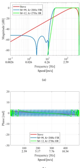
which agrees with Stove’s analysis for stationary targets. With the response shown in Eq. (14), it can be seen that when fDT is an integer, there is a zero in the filter response. These zeros are known as blind speeds as the output of the MTI filter will be absent of any targets moving at these speeds. The filter response of the single-delay filter is shown in Fig. 2, compared with another example higher-order FIR filter (whose design will be explained in Section IV). The filter is designed for a 2ms chirp, hence the first blind speed appears atfD= 1/T = 500Hz≡12.9m/s at5.8GHz in free-space.
These filters reject objects based on speed, and their re-sponse is identical for positive and negative speed (i.e. ve-locity). For unambiguous velocity measurements with FMCW radar, the following sampling rule must be satisfied [17]:
|fD| ≤ 1
2T (16)
T = 1/fs,D (17)
wherefs,D is the Doppler frequency sampling rate.
As has been shown, the single-delay filter is a first-order FIR filter. Hence, it can be extended to implement MTI filters of higher order, different filter types (high-pass or band-pass), and different cut-off frequencies [8], [9]. The cut-off frequencies are designed to attenuate unwanted/clutter signals based on the expectation of the unwanted/clutter signal speed [8]. Fig. 2 shows the response of a M = 99, high-pass FIR filter with a cut-off frequency offc= 20Hz for a 2ms chirp period, or
ωDT = 0.25rad. This filter was designed using the window method and a Hamming window to deliver a low-ripple pass-band [18] and has an improvement factor of some46dB. This filter was designed for use in a through-the-wall scenario, discussed in Section IV. Selection of the best window for a particular application is part of the MTI filter design process. The simplicity of adjusting the FIR MTI filter parameters also makes target segmentation based on target speed possible (something that is not possible with the background subtrac-tion technique). Hence, FIR MTI filtering is an extremely powerful tool as will be shown using measurement data in Section IV.
(a)
(b)
Fig. 2. (a) Magnitude and (b) phase frequency responses of example digital MTI filters.
C. IIR Filters for FMCW MTI
Additionally, IIR filters can be used where linear phase is not a requirement. IIR filters are able to achieve a comparable magnitude response as an FIR filter using many fewer filter taps. As a result, their group delay is much reduced. These characteristics can be of great use in MTI filters where the difference in terms of Doppler frequency between a stationary target and a target in motion can be very small. Such situations demand high-Q filters. With a FIR filter, this can only be achieved with a large number of filter taps, which becomes expensive in terms of logic implementation.
IIR filters are linear time-invariant systems whose outputs are formed from the inputs of the system and, crucially, the previous outputs of the system. They can be described by the following equation: yd[t, n] = N X l=1 al·yd[t, n−l] + M X k=0 bk·xd[t, n−k] (18) where two sets of filter coefficients, the feedback coefficients
of the filter. The order of the filter is defined as M.
Fig. 2 shows the response of a M = 12, high-pass FIR filter with a cut-off frequency of fc= 27Hz for a 2ms chirp period, or ωDT = 0.34rad. This shows the efficiency of a IIR filter relative to a FIR filter; the IIR filter has an order of magnitude less filter taps but has a very similar in-band magnitude performance and a larger improvement factor. As mentioned, this results in a shorter filter group delay and a more memory efficient implementation in digital devices such as a field programmable gate arrays.
As with FIR filters, target segmentation based on target speed is possible with IIR filters. The efficacy of the IIR filter relative to the FIR in theory should be very similar, and this assertion will be tested in the following section. However, the design of an IIR filter is a more complex process as it is possible that the introduction of feedback coefficients can cause the filter to be unstable. The stability of the IIR filter design can be tested but this requires an extra process, which is a disadvantage for adaptive systems.
IV. MTI PERFORMANCE WITHMEASUREMENTDATA
To test the efficacy of the FMCW MTI techniques described in this paper, measurements of humans in motion were taken using the UCL-developed Soprano radar system (the radar system is described in full in [19]) under two scenarios. These scenarios include a through-the-wall measurement of a person and measurement of two people in an open field.
Soprano is an FMCW radar system operating at 5.8GHz with a 20mW transmit power, a maximum bandwidth of
300MHz, and adjustable chirp period and receiver gain. At maximum gain, the receiver single sideband noise figure is some 2.5dB. At baseband, a second order high-pass active filter implements frequency gain control for efficient use of analog-to-digital-converter dynamic range.
A. Movement Detection for Through-The-Wall Radar
Through-the-wall radar is a widely researched and adopted technique for locating concealed individuals in security, mil-itary and disaster rescue applications [20]. In order to detect movements of targets behind the wall, a high performance MTI filter is necessary to remove the strong echo signal from the wall, which can be assumed to be stationary, whose range-sidelobes are likely to dominate echoes from targets behind the wall [2]. In order to test and critically analyse the MTI filters discussed in Section III, through-the-wall measurements using the Soprano radar were carried out.
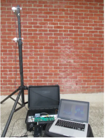
The radar was set up with colocated transmitter and receiver antennas (separated vertically by 0.5m for isolation) facing a wall 0.7m from the antenna phase centres. The antennas were 30◦ yagi antennas with a gain of 12dBi. The chirp parameters were set to a bandwidth of150MHz and a period of 2ms with a sawtooth modulation of up-chirps. From Eq. (16), this chirp period gives a maximum unambiguous velocity of±6.46m/s at5.8GHz. The cross section of the wall had an overall thickness of 300mm. The outer-facing section of the wall was made up of100mm clay brick, and the inner-facing section was made up of 100mm of concrete breeze block.
Both sections were separated by a100mm cavity, filled with insulation material. Fig. 3 shows an image of the experiment setup.
Fig. 3. Through-the-wall experiment setup.
Behind the wall, a person walked in a straight line away from and towards the radar within the main lobe of the antennas. The starting position of the person was up against the wall and they proceeded to walk to a position some 4m away from the wall.
The time domain data was split into returns from individual chirps and the MTI techniques described in Section III were each applied across the chirps. Following MTI filtering, a Hann windowed and zero-padded FFT with a padding factor of 5
was then performed on each individual chirp and the values of associated frequency bins were converted to range using Eq. (4). The result of this process is a 2-dimensional image with a time x-axis, a target range y-axis, and each pixel magnitude representing the target echo power.
The background subtraction filter used an estimate calcu-lated over 50 chirps (0.1s), which was updated every 0.1s. The single-delay, FIR and IIR MTI filters used the same design as those shown in Fig. 2.
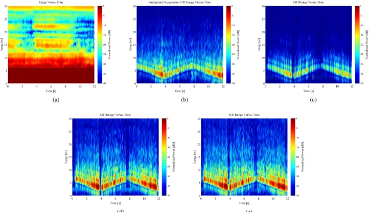
Fig. 4 shows the range versus time plots of the through-the-wall measurement prior to MTI filtering (Fig. 4a) and following MTI filtering using the various techniques.
Fig. 4a demonstrates the dominant response of the wall, masking targets of interest up to some 10m range. Indeed, the wall response dictates the amount of gain permitted in the receive chain, and hence limits the sensitivity level of the radar. The impact of the wall on the receiver sensitivity level cannot be rectified in signal processing. However, provided the targets behind the wall are moving and of great enough radar cross section to exceed the receiver sensitivity level, the targets are revealed following wall-removal using MTI filtering as demonstrated in Figures 4b-4e.
In addition, the Doppler signature of the data was examined by forming Doppler (velocity) versus time images. These were generated by taking an average of the FFT generated range profile for each chirp, and processing a spectrogram with100
-(a) (b) (c)
(d) (e)
Fig. 4. Comparison of performance of the four MTI filtering techniques under discussion on raw measurements of a person walking backwards and forwards behind a brick wall shown in range versus time plot (a); namely (b) background suppression estimated from a clutter frame averaged over and updated every
0.1s, (c) single-delay filter, (d) FIR filter with100taps and (e) an order12IIR filter whose filter responses are shown in Fig. 2.
chirp length, Hann shaped windows of averaged data, and80% window overlap.
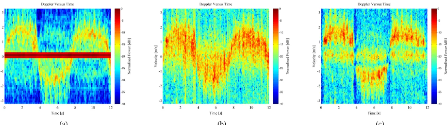
The spectrograms shown in Fig. 5 reveal the characteristic micro-Doppler signature of a walking person following the various MTI techniques. These images show comparable sig-natures to other FMCW human micro-Doppler measurements [21].
It is immediately clear from these images that each of the techniques perform some level of filtering of stationary clutter. The degree of success of each is variable and will be discussed fully in the Section V.
B. Multiple Target Segmentation
Segmentation of targets based on their speed is extremely useful to focus resources on particular targets. Applications of this technique include automotive radar, gesture recognition radar and surveillance radar.
The multi-target measurements described in this paper were again performed using the Soprano radar with chirp waveforms of 100MHz bandwidth and a period of1ms with a sawtooth modulation of up-chirps.
The radar was set up with colocated transmit and receive antennas in an empty field with minimal clutter as shown in Fig. 6. The setup included a 5.8GHz antenna target with an open-circuit feed as a stationary target located 50m from the radar, directed towards the radar transmit/receive antennas. This was used as a calibration target in other experiments. In this paper, we focus on a measurement of the following
sequence of events:
1. Individual person runs away from the radar to some50m range and then back towards the radar.
2. A different individual person runs away from the radar. 3. Both people walk in different directions (the former away from the radar and the latter towards the radar).
Fig. 7 shows a range versus time image of the raw, unfiltered radar data collected during the sequence of events. It is clear that objects are present that are moving in range. In addition, objects that are stationary in range are present. The stationary target at 55m range, which is the response from the antenna target, has some variation in return strength over time. It is believed that the people walking along the transmit/receive antenna and the antenna target baseline caused constructive and destructive interface with the target signal, which results in the target scintillation seen in this raw image. In particular, it is apparent that the target is in shadow when two people are walking between the radar and the target simultaneously between 45 and 70s, appearing strongly only at c. 58s. Between0and3m, the large response is a result of transmit to receiver direct coupling, which is reduced so as to not saturate the front-end and deramping mixer by separating the transmit and receiver antennas vertically. By keeping the receiver in its linear region in the presence of transmitter to receiver leakage, this artefact can be removed by digital MTI filtering.
Out of the three techniques described in Section III, only the FIR and IIR filtering techniques can be used on this dataset to segment the walking person and the running person. This is because the cut-off speed of the background subtraction
(a) (b) (c)
Fig. 5. Comparison of the spectrograms of raw through-the-wall measurements (a) and (b) the background suppression estimated from a clutter frame averaged over and updated every0.1s and (c) an order12IIR filter whose filter responses are shown in Fig. 2.
Fig. 6. Experiment setup in field with stationary target highlighted.
Fig. 7. Raw range versus time image of measurement of individuals running and walking.
technique cannot be specified easily.
Assuming that the preferred walking speed of humans is between 1.4m/s and 2m/s, and the human running speed is between3m/s and 12.4m/s (Usain Bolt, [22]), the two states can be segmented. Employing a bank of digital filters with different cut-off frequencies allows us to distinguish walking human targets, running human targets, and stationary clutter.
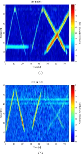
To segment the data, a bandpass filter with a ‘speed pass-band’ of0.5m/s to2m/s is used to capture the walking human data, and a high-pass filter with a ‘speed cut-off’,vc, of3m/s
is used to capture running human data. Using the equation for Doppler frequency
fc=
2fovc
c (19)
at 5.8GHz, this equates to Doppler cut-off frequencies of
19.3Hz and 80Hz for the walking human filter, and 116Hz for the running human filter. These frequencies were used as a guide for the design of the segmentation filters, which is summarised in Fig. 8. The filter orders were selected to provide an improvement factor of more than50dB.
Fig. 9 shows the resulting range versus time images after application of the described MTI filters to the dataset. It is clear from these images that using the described FIR and IIR digital filtering techniques, we are able to segment walking and running personnel, and suppress stationary clutter by more than 20dB. The resultant images are much clearer, giving automatic detection, and potentially classification, processes a greater chance of efficacy.
The cause of the stationary (constant range) features present in Fig. 9 are not known at present. However, it is likely that these are spurs are caused by switch mode power supply noise from the control laptop (these are not seen in the through-wall measurements, during which a metalised laptop was used with improved power supply shielding).
V. DISCUSSION
We have shown the outcomes of applying three different MTI filtering techniques to real FMCW radar measurement data, including through-the-wall and multi-target measure-ments.
The technique of subtracting an estimate of the background stationary clutter has been shown to be effective at removing stationary targets with minimal impact on slow-moving targets. This is particularly apparent when comparing Fig. 4b with Fig. 4d, and Fig. 5b with Fig. 5c, in which it can be seen that in the FIR/IIR filter cases, the person response is removed when stopping to turn around (at c.4s and7.8s). However, the cut-off frequency of the background subtraction filter cannot be adjusted, unless combined with a digital filtering technique. Hence, it is a multi-step process to design for a particular
(a)
(b)
Fig. 8. Magnitude response of segmentation MTI filters in (a) logarithmic frequency domain, and (b) linear speed domain. These filters include FIR and IIR filter with a walking human passband (c.19Hz to80Hz) in red and black, and a FIR and IIR filter with a running human high-passband (c.116Hz cutoff).
performance. Furthermore, the estimate of the background clutter needs to be continually updated, making for a more computationally expensive process. It can also be seen in Fig. 4 that the output signal-to-noise ratio of the moving targets following the subtraction using the aforementioned estimation process was lower than for the FIR/IIR techniques. This is likely to be due to leakage of the moving targets in to the estimate of the background stationary clutter.
The FIR filter technique is shown to have good perfor-mance for both moving target indication and moving target segmentation in both experiments. The filters are simple to design and implement, have easily adaptable parameters, and linear phase. However, achieving a sufficient filter roll-off, particularly for slow moving targets, can require very high order filters. This results in a great resource demand on the digital signal processor. Due to their inherent stability though, they are particularly useful for designing high Q-factor implementations.
The IIR filter technique shows similar performance to the FIR filters for the datasets discussed in this paper. They benefit from using less filter coefficients for the equivalent roll-off of a FIR filter. However, they can present a challenge to design, especially for higher order requirements. They have a non-linear phase characteristic, particularly near
cut-(a)
(b)
Fig. 9. Range versus time images of the same data as plotted in 7 following the application of (a) walking human passband FIR MTI filter, and (b) running human passband IIR MTI filter.
off frequencies. Furthermore, IIR filters are not well-suited to high dynamic range environments (> 60dB) where large clutter returns can produce transient ringing in the filters [23]. This issue can be resolved using tail cancellation techniques, such as truncated IIR filtering [24], [25]. These techniques have not been tested in this work due to the low-dynamic range environment encountered in these measurements.
VI. CONCLUSIONS
In this paper, we have presented several MTI digital filtering techniques for FMCW radar applications; background subtrac-tion, FIR filtering, and IIR filtering. Each of the tested MTI techniques have suitable applications. Background subtraction is well-suited for slow-moving targets. If moving target seg-mentation is required, the FIR and IIR filtering techniques are the simplest, one-step processes.
We have shown that the background suppression technique suppresses stationary clutter without a significant impact on slow moving targets. However, the technique is not flexible and cannot easily be used for target segmentation based on speed.
FIR and IIR digital filters are extremely flexible and their design can be easily managed to implement FMCW MTI filters and target segmentation filters. In particular, IIR filters demonstrate efficiency in terms of logic implementation, a
useful attribute for low-cost systems which normally employ the FMCW radar architecture.
ACKNOWLEDGMENT
The authors would like to thank the UCL Institute of Making for funding the hardware component of this project through the EPSRC Bridging the Gaps grant. In addition, the authors would like to thank the journal reviewers for their insightful suggestions.
REFERENCES
[1] M. Skolnik,Introduction to Radar systems, 3rd ed. McGraw-Hill, 2001, ch. 4, pp. 101–151.
[2] A. Martone, K. Ranney, and C. Le, “Noncoherent approach for through-the-wall moving target indication,”IEEE Transactions on Aerospace and Electronic Systems, vol. 50, no. 1, pp. 193–206, January 2014. [3] A. Martone, K. Ranney, and R. Innocenti, “Through-the-wall detection
of slow-moving personnel,” inProceedings of SPIE7308 Radar Sensor Technology XIII, April 2009.
[4] F. Adib, Z. Kabelac, D. Katabi, and R. C. Miller, “3D tracking via body radio reflections,” inProceedings of the 11th USENIX Symposium of Networked Systems Design and Implementation, Seattle, 2014, April 2014.
[5] H. Griffiths, “New ideas in FM radar,” Electronics Communication Engineering Journal, vol. 2, no. 5, pp. 185 –194, Oct 1990.
[6] J. Lien, N. Gillian, M. E. Karagozler, P. Amihood, C. Schwesig, E. Olson, H. Raja, and I. Poupyrev, “Soli: Ubiquitous gesture sensing with millimeter wave radar,” ACM Trans. Graph., vol. 35, no. 4, pp. 142:1–142:19, Jul. 2016. [Online]. Available: http: //doi.acm.org/10.1145/2897824.2925953
[7] Z. Ali, A. Arshad, and U. Razzaq, “An FPGA based semi-parallel architecture for higher order moving target indication (MTI) processing,” inProceedings of 2010 21st IEEE International Symposium on Rapid System Protyping, June 2010, pp. 1–7.
[8] Y. V. Goncharenko, G. Farquharson, V. Gorobets, V. Gutnik, and Y. Tsarin, “Adaptive moving target indication in a windblown clutter environment,”IEEE Transactions on Aerospace and Electronic Systems, vol. 50, no. 4, pp. 2989–2997, October 2014.
[9] A. Sume, M. Gustafsson, M. Herberthson, A. Janis, S. Nilsson, J. Rahm, and A. Orbom, “Radar detection of moving targets behind corners,”
IEEE Transactions on Geoscience and Remote Sensing, vol. 49, no. 6, pp. 2259–2267, June 2011.
[10] A. Stove, “Linear FMCW radar techniques,”IEE Proceedings For Radar and Signal Processing, vol. 139, no. 5, pp. 343–350, 1992.
[11] E. Hyun, Y.-S. Jin, and J.-H. Lee, “A pedestrian detection scheme using a coherent phase difference method based on 2D range-doppler FMCW radar,”Sensors, vol. 16, no. 1, 2016.
[12] E. Hyun, Y. S. Jin, and J. H. Lee, “Moving and stationary target detec-tion scheme using coherent integradetec-tion and subtracdetec-tion for automotive FMCW radar systems,” in2017 IEEE Radar Conference (RadarConf), May 2017, pp. 0476–0481.
[13] A. Hymans and J. Lait, “Analysis of a frequency-modulated continuous-wave ranging system,”Proceedings of the IEE - Part B: Electronic and Communication Engineering, vol. 107, no. 34, pp. 365 –372, July 1960. [14] L. Qiu, T. Jin, J. Zhang, B. Lu, and Z. Zhou, “An iterative singular vector decomposition based micro-motion target indication in through-the-wall radar,” in 2016 IEEE International Geoscience and Remote Sensing Symposium (IGARSS), July 2016, pp. 6597–6600.
[15] M. Ritchie, M. Ash, Q. Chen, and K. Chetty, “Through wall radar clas-sification of human micro-doppler using singular value decomposition analysis,”Sensors (Basel, Switzerland), vol. 16, no. 9, August 2016. [16] J. H. McClellan, R. Schafer, and M. Yoder,DSP First, 2nd ed.
Prentice-Hall, 2015.
[17] V. Winkler, “Range Doppler detection for automotive FMCW radars,” in
European Radar Conference, 2007. EuRAD., Oct. 2007, pp. 166 –169. [18] F. J. Harris, “On the use of windows for harmonic analysis with the discrete Fourier transform,”Proceedings of the IEEE, vol. 66, no. 1, pp. 51–83, 1978.
[19] M. Ash, M. Ritchie, K. Chetty, and P. V. Brennan, “A new multistatic FMCW radar architecture by over-the-air deramping,” IEEE Sensors Journal, vol. 15, no. 12, pp. 7045–7053, Dec. 2015.
[20] H. Burchett, “Advances in through wall radar for search, rescue and security applications,” in2006 IET Conference on Crime and Security, June 2006, pp. 511–525.
[21] P. van Dorp and F. Groen, “Human motion estimation with multiple frequency modulated continuous wave radars,” IET Radar, Sonar & Navigation, vol. 4, no. 3, pp. 348–361, June 2010.
[22] D. Quarrell. (2016, December) How fast does usain bolt run in mph/km per hour? is he the fastest recorded human ever? 100m record? Online. Eurosport.com.
[23] R. H. F. Jr. and D. W. Burlage, “Improved moving-target-indicator filtering for phased array radar,” Army Missile Command, Tech. Rep., 1973.
[24] A. Kurosu, S. Miyase, S. Tomiyama, and T. Takebe, “A technique to truncate IIR filter impulse response and its application to real-time implementation of linear-phase IIR filters,”IEEE Transactions on Signal Processing, vol. 51, no. 5, pp. 1284–1292, May 2003.
[25] A. Wang and J. O. Smith, “On fast FIR filters implemented as tail-canceling IIR filters,”IEEE Transactions on Signal Processing, vol. 45, no. 6, pp. 1415–1427, Jun 1997.