Speed Control of an Induction Motor Using Ga Based Direct
Torque Control
K. Mohan PG Scholar,
Department of Electrical Engg, Anil Neerukonda Institute of Technology and Sciences, PO Box: 531162, Visakhapatnam, Andhra Pradesh, India
Ch. V. N Raja(Ph. D)
Assistant Professor,
Department of Electrical Engg, Anil Neerukonda Institute of Technology and Sciences, PO Box: 531162, Visakhapatnam, Andhra Pradesh, India
Abstract
Direct torque control (DTC) is a vector control strategy and it became very popular from previous two decades. The popularity is due to very fast dynamic torque response, simple structure, no coordination transformation required and absence of current and PWM controllers. In DTC, reference flux and speed are acts as inputs. Based on the errors between reference and estimated quantities and position of stator flux vector in two dimensional complex plane, voltage vectors are determined by the assisting of switching table. Variable speed control drives plays an crucial role in industrialization, so this paper concentrates on speed control technique of an induction motor using DTC strategy and also to improve the performance characteristics, speed controller gains are tuned by means of Genetic Algorithm (GA). GA gives best fit value and corresponding controller gains are selected to tune the controller which gives better performance characteristics. And also this paper describes, variation of controller parameters and steady state speed with respect to iterations. Induction motor is modeled in stationary reference frame and performance characteristics are observed by the help of SIMULINK/MATLAB.
Keywords: Induction motor (IM), Direct torque control (DTC), Genetic Algorithm (GA). 1. Introduction
In this epoch of industrialization advanced motion control and high performance electric drives plays a central role for the product quality and productivity for a developing economy. Although most of the variable speed drives employs DC machines, they are replaced by AC drives, particularly, squirrel cage induction motor drives due to their advantages. Induction motors are extensively used in industries due to its simple construction, lower maintenance, easier to design than DC machines, reliability, over load capacity and self starting. A continuous research is going on an optimal control of an induction motor drives.
P.L.Alger, et.al, explains the history of induction motor from its invention by Nicole tesla through the various stages [1] of its development as, the innovation of the cast aluminum squirrel cage winding, improvements in magnetic steel and insulation, and the progressive decline of the dimensions for a given horse power rating. T.Kataoka, et.al, proposed a method for induction motor loads in electric power system [2] for determination of the equivalent circuit parameters. PeihuHao, et.al, proposed a new energy saving scheme [3] of voltage regulation control of induction motors at sporadically changing loads by nearly constant speed. He analyzed the current oscillation in voltage regulation with synchronous voltage signal. Aldo Boglietti, et.al, proposed the potential applicability for the determination of efficiency of inverter fed induction motor [4] valid sinusoidal supply and PWM inverter supply standard commission members working on the definition of tests produced.
Pabitra kumar behra, et.al, proposed a scalar control strategy to control the speed of induction motor by varying supply frequency and applied voltage by keeping (v/f) ratio as [5] constant and also presented open loop and closed loop v/f control of an induction motor. Madhavi L.mhaisgawali, et.al, proposed speed control of an induction motor by means of PID controller by using vector control technique and analyzed performance curves without controller and with PID controller[6]. G.Kohlrusz, et.al, distinguished scalar control strategy from vector control strategy [7] of an induction motor. And also stated that vector control is a complex technique, but it is commonly used in industries since scalar control cannot be applied to systems with dynamic behavior. Srujana dabbeti, et.al, proposed speed control strategy of an induction motor with predictive torque [8] and current controllers and without using sensors. Sandeep Goyat, et.al, suggested field orient control (FOC) strategy to control the speed [9] of an induction motor and developed FOC algorithm. D.H Choi, et.al, implemented vector control scheme of induction motor to control speed in field waning region by tuning mutual inductance [10] and rotor time constant.
Takahashi and Noguchi [11] proposed a new technique for the control of induction motor, quite different from field oriented control based on limit cycle control of both torque and flux using optimum PWM
output voltage which gives quick torque response and is highly efficient. Here efficiency optimization in steady state operation has been considered and this proposed control circuit has the disadvantage of making some drift in extremely low frequency operation which can however be compensated easily and automatically to reduce the effect of variation of machine constant. Thomas G Habetler [12] proposed a DTC strategy of an induction machine based on predictive, deadbeat control of the flux and torque. Here variations in torque and flux over the switching period is analyzed by estimating the voltage behind the transient reactance and the synchronous speed. The stator voltage is calculated which is required to track the reference flux and torque. Then Space vector PWM is used to define the inverter switching state. An alternative approach to deadbeat control is also implemented.
Prof.Dr.A.K.M Al-Shaikhil, et.al, suggested DTC scheme of an induction motor based on Genetic Algorithm (GA). Here to improve the performance of DTC, stator resistance is optimized by using GA, generated input/output data is used to train the neural network[13]. R.Essakirai, et.al, proposed speed control technique[14] of an induction motor by employing GA based PID controller. Here optimization is done by using mean of square error and PID parameters are tuned which gives best fit values by GA.
In this paper, induction motor modeling explains in section 2. The DTC control strategy is explains in section 3. Section 4 explains tuning of speed controller by GA technique. Section 5 presents simulation results. 2. Induction Motor Model
For steady state analysis of an induction motor, analysis of per phase equivalent circuit is sufficient. But for transient response analysis of per phase circuit is not sufficient. So induction motor is modeled in dynamic α-β model to examine the transient response. Initially we have to convert three phase voltages to two phase voltages by using simplified clarke transformation. So abc to α-β transformation is given as:
1
0 √ √ (1)
And α-β to abc transformation is done by inverse Clarke transformation as: 0 √ √ (2)
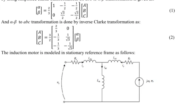
The induction motor is modeled in stationary reference frame as follows: Figure 1. Per phase equivalent circuit of induction motor Consider per-phase equivalent circuit shown by figure 1. The circuit consists, resistance and leakage inductance of stator, mutual inductance, resistance and inductance of rotor and induced voltage. The induction motor in arbitrary reference frame K can be presented per unit rotating angular speed ωk as: !"# $ %& ' (3)
( ( ! $)# %*& &(+' (4)
' , ,- ( (5)
'( ,( ( ,- (6)
The currents relations are: ."' ./ ." ( (7)
( .)'( ../) (8)
The induction motor (IM) model presented in per unit in the rotating frame with arbitrary speed is given by [15] as: 0"1 2 3".)453).4/ .)67 8 3)./ .)67'(8 & 9 &( ./ 67'(9 .) 67 8 (9)
0": 2 3".)453)./4 .)67 9 3)./ .)67'(9 & 9 &( ./ 67'(8 .) 67 9 (10) !)1 2 3) .)'(8 &('(9 3)./ .) 8 (11) !): 2 3) .)'(9 &('(8 3)./ .) 9 (12)
The mathematical model of IM as differential equations of state variables presented in (αβ) stationary reference frame and (ωk = 0) is:
0"; $ < = < '(= &(< '(> <? = (13) 0"@ $ < > < '(> &(< '(= <? > (14) !); $ <A'(= * &(+'(> <B = (15) !)@ $ <A'(> * &C+'(= <B > (16) Where, < ,(, (, -(D , < (, -,(D , < , -D , <? ,D( <A ,D , <( B (,, -( , D G, ,( ,(, ,- , G 1 , -, -,(
3. Direct Torque Control
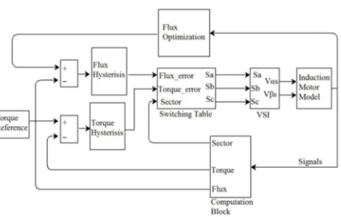
Control of induction motor’s flux and torque is impossible in coupled nature. Both variables are subjected to input voltage, while the speed is dependent on input AC supply frequency. As the control of DC motor, the DTC enables decoupling of torque and flux of induction motor by identifying the effect of voltage source inverter (VSI). The DTC involves direct control of torque and flux by estimation using voltages and currents. The DTC control is sub-divided into three blocks as:
An induction motor model block, which represents the induction motor model in stationary reference frame. This model estimates the electromagnetic torque developed, the rotor speed and the stator flux by measuring motor currents and flux linkages.
Hysteresis controller block, compares flux and torque reference with actual torque and flux estimated by model. Switching state control block, which translates controller outputs into proper signals to the power switching device. If stator resistance is neglected, the voltage space vector HI is related to flux space vector 'JJJas:
HI $*'JJJ+ (17) Or
Δψ
JJJJJ HIΔM (18)
So increment in the stator flux 'JJJ can be obtained by applying stator voltage vector HI in the interval of ΔM. By controlling the proper inverter states, a desired locus of stator flux is obtained [16]. By assuming the rotor flux time constant is large compared to the stator flux time constant, the stator flux changes quickly compared with the rotor flux. The two reference inputs to the DTC strategy are torque and flux signals. A comparison made between the reference and estimated quantities of torque and flux by Hysteresis controllers. Then hysteresis bands are set for two quantities. Increase / decrease in torque and / or flux are determined by hysteresis controllers.
The plane, in which stator flux vector changes its position, is divided into six sectors. The sector number and digital output from hysteresis controller are used to control input voltage, to track desired quantities. At the end of every sampling interval, corresponding voltage vectors are chosen to maintain the magnitude of error of stator torque and flux within the limits determined by hysteresis bands. The switching frequency of inverter is affected by width of the hysteresis bands. Lower the band, wider the switching frequency and rich in response.
The basic DTC scheme of an induction motor drive is shown in the figure 2. The scheme can be divided into two parallel controls: the torque control and the flux control. DTC scheme operates in two modes, The torque control mode, where reference torque command is applied directly and speed control mode, where the reference torque is obtained as output of a speed controller. The torque, flux magnitude and flux vector position is calculated in the signal computation block.
Figure 2. Conventional DTC strategy In essence, the DTC strategy can be categorized into the following sub-units: A. Flux Estimator
From the α-β voltages and currents input to the induction motor model, the stator flux can be estimated using the below equations:
'= N* = = +OM (19)
'> NP > > QOM (20)
|' | S'= '> (21)
B. Torque Estimator
The estimated torque of the motor model can be computed as:
TU VP'= > '> = Q (22) C. Sector Calculator
There are six sectors, each W angle wide. To determine the operating sector of the motor, the flux vector angle X can be determined as:
X M<YZ [!@"
!;"\ (23)
Depending on the angle of the flux vector, the correct sector ]ZB is selected. D. Flux and Torque Hysteresis Comparators
The flux controller is a two level digital output controller which produces output based on the following relations: ^! 1 for _!` ^ ! (24)
^! 0 for _! a ^ ! (25) Where 2^ ! is the total hysteresis band width of the flux controller.
The torque controller has three levels of digital output with the following relations :
^cU 1 for _cU` ^ cU (26) ^cU 1 for _cUa ^ cU (27)
^cU 0 for ^ cUa _cUa ^ cU (28)
The third digital output for the torque controller is used to keep the torque constant. E. Switching Table
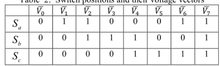
The states from the hysteresis comparator are examined by the controller block together with the calculated sector number and the appropriate voltage vector from Table 1is chosen.
Table 1: Switching table for voltage vectors
Hysteresis Controller Outputs Sector
1 2 3 4 5 6 ^! 1 ^cU 1 HI HI HI? HIA HIB HI ^cU 0 HId HIe HId HIe HId HIe ^cU 1 HIB HI HI HI HI? HIA ^! 0 ^cU 1 HI HI? HIA HIB HI HI ^cU 0 HIe HId HIe HId HIe HId ^cU 1 HIA HIB HI HI HI HI?
Table 2: Switch positions and their voltage vectors HId HI HI HI HI? HIA HIB HIe a
S
0 1 1 0 0 0 1 1 bS
0 0 1 1 1 0 0 1 cS
0 0 0 0 1 1 1 1F. Voltage Source Inverter
DTC wants an inverter to translate the low voltage control signals to high voltage signals to drive the motor. The inverter is linked to the motor terminals and is controlled by three signals Sg,h,i. Each of the three phases has two switches. A low l switch and a high h switch, which are controlled by the signals. When signal ]j is high, switch k is turned on whereas switch l is turned off. When signal ]j is low, switch k is turned off whereas switch l turned on. An analogous approach is used for switches B and C.
The states of the switches are used to implement the VSI. The voltage vector equation as outlined is: HI H m ]j ]nop
4q
r ]soptqr (29) G. Speed Controller
In the torque control mode, a reference torque is applied as input to the control strategy. Whereas, in the speed control mode, a proportional integral or a proportional-integral-derivative controller is used as speed controller. The speed error obtained by comparing the reference speed and the estimated speed acts input to the speed controller.
Figure 3: obtaining reference torque using speed controller Estimated speed &( can be computed by using below equation,
u) $
V
v*TU Tl+ (30)
For improved performance of the controller, an anti-wind up based PI controller is used as a speed controller [15].
4. Genetic Algorithm
GA optimization technique is recently getting growing in the field of sensitive control applications. GA is a form of stochastic global adaptive search optimization technique simulated from genetic and evolution mechanisms located inside the natural choice. GA was first recommended in 1975 by means of John Holland and his colleagues. It makes use of the manner that nature uses for growing the fittest individual – Selection, Crossover, Mutation and accepting. Those are referred to as genetic operators on the idea of which the best individual of a population are selected to supply the subsequent era of individuals with progressed traits as compared to that of the preceding era. The individuals of the population are represented in the form of chromosomes either in binary form represented in the form of bits consisting of ‘0’s and ‘1’s or can be real coded depending upon the application. The illustration in binary form is easier to function on thinking about the crossover and mutation operators. The space which include all possible viable solutions is called search space. Every point in the search space exists of a viable solution.
A fitness function describes the portions on which the manipulation of facts takes place. It can be either a maximization function or minimization function. As an example, the difference between the actual speed and the reference speed of the machine have to be less. Here, the fitness function, which may be the speed error, ought to be minimized in order that the machine overall performance may be advanced [17]. Selection is the system in which members of the population are decided on consistent with their fitness. Fitness is decided by means of calculating how well each member fits an objective function. There are many strategies of selection of which Roulette Wheel Selection (RWS) is marked as the most easiest and simple process. The individuals that are carried to the next generation undergo crossover and mutation. Crossover is a procedure wherein each pair of individuals jointly interchanges a randomly decided on portion of bits to provide variety. There are numerous sorts of crossover particularly, single point crossover where the parental chromosomes are split at a randomly
determined crossover point, two point crossover in which the parental chromosomes are breakup at two arbitrarily determined crossover point, uniform crossover in which the integration ratio of the parents is decided through their offspring, intervening crossover produces a weighted median of the parents and arithmetic crossover generates progeny which the weighted arithmetic median of their parents. Mutation is the subsequent process that alters a gene in the chromosome from ‘0’ to ‘1’ and vice versa to forestall the chromosomes from losing helpful data [18].
4.1 Tuning of speed controller parameters by GA:
The dynamic model of the speed induction motor drive with speed controller is significantly simplified, and can be easily represented with the block diagram shown in Figure 4 [17].
Figure 4 : Block diagram of speed system with controller
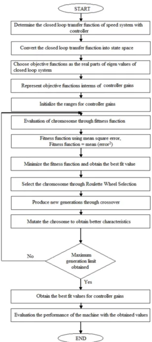
Step by step route is given as flow chart in figure 5 to tune the controller gains by using GA. The controller parameters are tuned by using Genetic Algorithm with the error in voltage, got as an equivalent with respect to speed, as the objective function.
The fitness function is based on Mean Square Error (MSE), w]_ x∑ P&{ ∗*M+ &*M+Q
0 (31)
where &∗*M+ is reference speed, &*M+ is estimated speed and n is the index number.
Implementation of GA based controller for speed control of induction motor is described as algorithm given below.
i. Find out the closed loop transfer function of speed system with controller shown by figure 4. ii. Convert the closed loop transfer function into state space model.
iii. Choose real parts of eigen values of closed loop system as objective functions interms of controller parameters.
iv. Initialize the ranges for controller gains.
v. Run the Genetic Algorithm and choose the best fit values for controller parameters.
The fitness function is minimized by using Genetic Algorithm. The best fit values are achieved for the controller gains by use of genetic operators to determine variety in the individuals of a population. The iteration procedure is achieved until the maximum generation limit is obtained.
5. Simulation Results
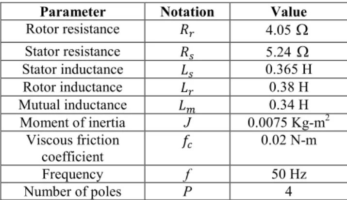
In this paper, speed control of induction motor using DTC strategy proposed in above sections has simulated for 0.6 sec, reference speed is 100 rad/sec and parameters of speed controller are tuned by the GA optimization technique to progress the response characteristics. The parameters of induction motor used in the developed models are shown in table 3.
Table 3 : Parameters of Induction Motor
Parameter Notation Value
Rotor resistance ( 4.05
Ω
Stator resistance 5.24Ω
Stator inductance , 0.365 H Rotor inductance ,( 0.38 H Mutual inductance ,- 0.34 H Moment of inertia J 0.0075 Kg-m2 Viscous friction coefficient |m 0.02 N-m Frequency f 50 Hz Number of poles P 4Figure 6 : Speed performance curves with conventional PI, PID controllers
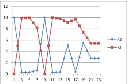
Figure 7 : Variations of Kp, Ki of GA-DTC PI for each iteration
Figure 8 : Variations of Kp, Ki of GA-DTC PID for each iteration 0 2 4 6 8 10 12 1 3 5 7 9 11 13 15 17 19 21 23 Kp KI 0 2 4 6 8 10 12 1 3 5 7 9 11 13 15 17 19 21 23 Kp Ki
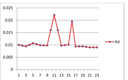
Figure 9 : Variation of Kd of GA-DTC PID for each iterations
Figure10 : Variations in speed with GA-DTC PI for each iteration
From figure 10, all iterations gives good steady state speed but transient response is very poor except last three iterations. But transient response is also a constraint in the case of high performance drives. The last three iteration parameters are approximately same and gave acceptable steady state response as well as transient response. So selected GA-DTC PI controller parameters are }~ 2.757,}0 5.447. And also transient response improved over iteration.
Figure 11 : Variations in speed with GA-DTC PID for each iteration
From figure 11, concluded that all iterations gave good steady state response, but gave poor transient 0 0.005 0.01 0.015 0.02 0.025 1 3 5 7 9 11 13 15 17 19 21 23 Kd 99 99.5 100 100.5 101 101.5 102 1 3 5 7 9 11 13 15 17 19 21 23 Speed 100.6 100.8 101 101.2 101.4 101.6 101.8 102 1 3 5 7 9 11 13 15 17 19 21 23 speed
response except last three iterations. The last three iteration parameters are approximately same. So selected GA-DTC PID controller parameters are }~ 10 , }0 2 and } 0.009. And also observed that, the transient response decreased by increasing number of iterations.
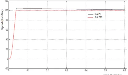
Figure 12 : Speed performance curves with GA-DTC PI, GA-DTC PID controller
From figure 6 and 12, concluded that by using GA based controllers settling time and resonant peak are reduced and also there is negligible change in rise time.
Figure 13 : Torque with GA-DTC PID
Figure 14 : Three phase stator currents with GA-DTC PID 6. Conclusion
In this paper, Initially reference and estimated values of signals are used to generate error signals. These error signals are passed through hysteresis bands, based on the actual stator flux, torque and position of flux vector inverter states are determined to track the reference speed. Finally, speed controller parameters are tuned with the help of GA optimization technique and response characteristics are improved. Hence by using GA based controllers, performance curves of an induction motor are improved and also undesirable conditions are
eliminated, smooth control is possible. References
[1]. P.L.Alger. (1916), “History of induction motors”, Proceedings of the IEEE (Volume:64, Issue:9), pp. 1380-1383.
[2]. T.Kataoka, H.Uchida, T.Kai, T.Funabashi. (2000,December), “Method for aggregation of a group of induction motor loads”, Power system technology, proceedings, powercon international Conference, volume 3, pp. 1683-1688.
[3]. PeihuaHao, Ming Cheng, Ruiwucao and Yubin Wang.(2010), “Induction motor energy saving strategy using voltage regulation control”, ICEMS 2010 International conference, pp. 1351-1356.
[4]. Aldo, Andrea, Macro and Albert Teconi.(2013), “Efficiency determination of converter fed induction motors”, IEEE Energy Conversion congress and Exposition, pp. 230-237.
[5]. Pabitrakumarbehra, Manoj Kumar Behera and Amit Kumar Sahoo.(2014), “Speed control of induction motor using scalar control using scalar control technique”. IJCA, International Conference on emergent trends in computing and communication (ETCC-2014).
[6]. MadhaviL.mhaisgawali, Prof. Mrs. S.P Muley.(2011), “Induction motor speed controlling using PID controller”, IJTES, Vol 1(2), pp. 151-155.
[7]. G.Kohlrusz, D.Fodor.(2011), “Comparison of scalar and vector control strategies of induction motor”, Hungarian journal of industrial chemistry Veszprem, Vol. 39(2), pp. 265-270.
[8]. Srujana Dabbeti, K.Vara Lakshmi. (2013,Jul-Aug), “Sensorless speed control of induction motor drive using predictive torque and current controllers”, IJERA, Vol. 3 ( Issue 4 ), pp. 2683-2691.
[9]. Sandeep Goyat, Rajesh Kr. Ahuja. (2012.July ). “Speed control of induction motor using vector or field oriented control ”, IJAET, Vol. 4 (Issue1), pp.475-482.
[10]. D.H Choi, M.H Shin, T.K Lee, S.B Cho, D.S Hyun. (1997), “Vector control of an induction motor for the Field weaking region wih tuning of the magnetizing inductance”, power conversion Conference,Vol.1. [11]. Takahashi Isao, Noguchi Toshihiko “A new quick response and high efficiency control strategy of an
induction motor”, IEEE transcations on industrial applications, Vol. IA -2. No-5, Sept/Oct 1986.
[12]. Thomas G. Habetler, Francesco Profumo, Pastorelli and Leon M. Tolbert “direct torque control of IM using space vector modulation”, IEEE transcations on industrial applications, Vol. 28, No.5, Sept/Oct 1992. [13]. Prof.Dr.A.K.M Al-Shaikhil, Dr.Saadi A.Khudair, Dr.Kannan A.Jalal, Luay G.Ibrahim, “ Direct torque
control of induction motor based on genetic algorithm”, International Journal of Scientific & Engineering Research, Vol.5, Issue 12, December-2014.
[14]. R.Essakiraj, K.Preetham Rengarajan, S. Visakan, G.S Vinay kaushik and C.Kamalakannan, “Speed control of induction machines using GA based PID controller”, Middle-East Journal of Scientific Research 23 (sensing, signal processing and security), pp. 164-169, 2015.
[15]. Haitham Abu-Rub, Atif Iqbal, and Jaroslaw Guzinski, “High performance control of AC drives ”, First edition. John wiley & Sons. Ltd, 2012.
[16]. Peter Vas, “Sensorless Vector and Direct Torque Control”, Oxford University Press, 1998.
[17]. Mohammad Chebre, Abdelkader Meroufel and Yessama Bendaha, “speed control of induction motor using GA based PI controller”, Acta Polytechnica Hungeria, Vol.8, No.6, pp.141-153, 2011.
[18]. Megha, Jaiswal and Mohna Phadnis, “Implementation of GA based PID Controller for speed control of DC motor”, International Journal of Advanced Research in Computer science and Software Engineering, Vol.3, No.7 pp.247-253, 2013.