Comparative Study between PI and FUZZY Logic Speed
Controller in Vector Controlled PMSM Drive
Kaushik Jash*, Nirban Chakraborty**, Prof. Pradip Kumar Saha***, Prof.
Goutam Kumar Panda****
*(PG scholar, Department of Electrical Engineering, Jalpaiguri Government Engineering College, Jalpaiguri, West Bengal, India, Pin.-735102)
** (PG scholar, Department of Electrical Engineering, Jalpaiguri Government Engineering College, Jalpaiguri, West Bengal, India, Pin.-735102)
*** (Professor, Department of Electrical Engineering, Jalpaiguri Government Engineering College, Jalpaiguri, West Bengal, India, Pin.-735102)
**** (HOD and Professor, Department of Electrical Engineering, Jalpaiguri Government Engineering College, Jalpaiguri, West Bengal, India, Pin.-735102)
ABSTRACT
This paper is concerned with vector control of permanent magnet synchronous motor (PMSM) using two different type of speed controller, one is PI controller and another is FUZZY logic controller. Although Proportional Integral Controller usually preferred as a speed controller due to its fixed gain and integral time constant but the performance of PI controller is affected by parameter variation, such as load changing, speed variation etc. In PI controller THD of the stator phase current is more and torque ripple also more. To avoid this problem here we used FUZZY logic controller. In this paper the mathematical model of PMSM, using the powerful simulation modeling capabilities of Matlab/Simulink is implemented. The entire PMSM control system is divided into several independent functional modules such as PMSM body module, inverter module and coordinate transformation module and Sinusoidal pulse width modulation (SPWM) production module and so on. Here we used two loops, one is outer loop known as speed control loop, another is inner loop called current loop. we can analyzed a variety of simulation waveforms and it provide an effective means for the analysis and design of the PMSM control system.
Keywords
– FUZZY logic speed controller, Mathematical model of Permanent magnet synchronous motor, Park Transformation, Sinusoidal pulse width modulation, Vector control.I.
INTRODUCTION
Compared with other forms of motor, Permanent magnet synchronous motor (PMSM) has better dynamic performance, smaller size and higher efficiency. In recent years, with the rapid development of electric power electronics technical, rare earth permanent magnetic materials and the increasingly sophisticated research in Permanent magnet motor. PMSM is widely used in national defense, agriculture and daily life [1]. PMSM is a multivariable, nonlinear and high coupling system. The output torque and stator current present a complicated function relation. Magnetic field can be decoupled to get a good control performance. It was no slip frequency current, less affected by the rotor parameters, easier to implement vector control [2]. Therefore, the model of PMSM vector control has become a widespread concern. Ideally, a Vector controlled PMSM drive operates like a separately excited dc motor drive. Because of dc machine like performance, Vector control is also known as
decoupling or orthogonal control. DC machine like performance can also be extended to a PMSM if the machine control is considered in a rotating reference frame (rotating with rotor), where the sinusoidal variables appear as dc quantities in steady state. The Vector Control of PMSM consists of controlling the stator currents represented by a vector. This control is based on projections which transform a three phase time and speed dependent system into a two co-ordinate (d and q co-co-ordinates) time invariant system (using Park’s transformation). These projections lead to a structure similar to that of a DC machine control. Vector controlled machines need two constants as input references: the torque component current (aligned with the q co-ordinate) and the flux component current (aligned with d co-ordinate). The torque component current controls the torque and flux component current controls the flux of the machine independently. Therefore by using Vector control, independent control of the torque and flux producing currents are possible. This paper is
concerned with vector control of permanent magnet synchronous motor (PMSM) using two different type of speed controller, one is PI controller and another is FUZZY logic controller. Although Proportional Integral Controller [3] usually preferred as a speed controller due to its fixed gain and integral time constant but the performance of PI controller is affected by parameter variation, such as load changing, speed variation etc. In PI controller THD of the stator phase current is more and torque ripple also more. To avoid this problem here we used FUZZY logic controller.
The concept of FUZZY logic is first developed by Lotfi Zadeh in 1965. FUZZY logic embodies human like thinking into a control system. There is no need of mathematical models to deal with a problem, but skill is needed to create the rules in a particular FL controller [4], [5], [6]. The FLC is a multi-parameter controller, whose performance depends on the selected shape of membership function, rule-base and scaling factor. In this paper, rule base is viewed as control strategy to simplify the FLC. In this paper FLC is used for speed control loop. Here we used three triangular and two trapezoidal membership functions with overlap for speed error and similarly five for change in speed error. Therefore 25 rules are used to design the FUZZY logic controller.
II.
P
MSM DRIVE SYSTEMA general structure of speed control system for vector control of PMSM drive system is shown in Fig.1. The drive consists of FLC, PWM current controller, voltage source inverter, speed sensor, PMSM. The rotor speed ωr is compared with the
reference speed ωr* and the speed error is processed
in the FUZZY logic controller (FLC). The output of the speed controller is the q axis reference current
𝑖𝑞*. The d axis current is normally zero for constant torque region. The q axis and d axis stator current is transformed into 𝑖𝑎𝑏𝑐* current by inverse Park’s transformation. This current is compared with the actual motor (𝑖𝑎𝑏𝑐) current to generate the pulses for sinusoidal PWM inverter. Thus by obtaining the winding currents of system, speed response can be obtained.
Fig.1 Vector control of PMSM drive
III. M
ODELING OFPMSM
The mathematical model is similar to that of the wound rotor synchronous motor. Since there is no external source connected to the rotor side and variation in the rotor flux with respect to time is negligible, there is no need to include the rotor voltage equations. Rotor reference frame is used to derive the model of the PMSM [7], [8].
The electrical dynamic equation in terms of phase variables can be written as:
𝑣𝑎 = 𝑅𝑎𝑖𝑎 + 𝑝𝜆𝑎 𝑣𝑏 = 𝑅𝑏𝑖𝑏 + 𝑝𝜆𝑏
𝑣𝑐 = 𝑅𝑐𝑖𝑐 + 𝑝𝜆𝑐 (1) While the flux linkage equations are:
𝜆𝑎 = 𝐿𝑎𝑎𝑖𝑎 + 𝐿𝑎𝑏𝑖𝑏 + 𝐿𝑎𝑐𝑖𝑐 + 𝜆𝑚𝑎 𝜆𝑏 = 𝐿𝑎𝑏𝑖𝑎 + 𝐿𝑏𝑏𝑖𝑏 + 𝐿𝑏𝑐𝑖𝑐 + 𝜆𝑚𝑏
𝜆𝑐 = 𝐿𝑎𝑐𝑖𝑎 + 𝐿𝑏𝑐𝑖𝑏 + 𝐿𝑐𝑐𝑖𝑐 + 𝜆𝑚𝑐 (2) Considering symmetry of mutual inductances such as Lab = Lba, self inductances Laa = Lbb =Lcc and flux linkage λma = λmb = λmc = λm.
Applying the transformations for voltages, flux linkages and currents from equation (1)-(2), we get a set of simple transformed equations as:
𝑣𝑞 = (𝑅𝑠 + 𝐿𝑞𝑝)𝑖𝑞 + 𝜔𝑟𝐿𝑑𝑖𝑑 + 𝜔𝑟𝜆𝑚
𝑣𝑑 = (𝑅𝑠 + 𝐿𝑑𝑝)𝑖𝑑 - 𝜔𝑟𝐿𝑞𝑖𝑞 (3) The electromagnetic torque Te can be represented as:
𝑇𝑒 = (3/2)(𝑃/2)( 𝜆𝑚𝑖𝑞 + (𝐿𝑑 - 𝐿𝑞)𝑖𝑑𝑖𝑞) (4) The equation for motor dynamics is:
𝑇𝑒 = 𝐽𝑝𝜔𝑟 + 𝐵𝜔𝑟 + 𝑇𝑙 (5)
IV. V
ECTOR CONTROLVector control is also known as decoupling or field orientated control. Vector control decouples three phase stator current into two phase d-q axis current, one producing flux and other producing torque. This allows direct control of flux and torque. So by using vector control, the PMSM is equivalent into a separately excited dc machine. The model of PMSM is nonlinear. So by using vector control, the
model of PMSM is linear. Three phase stator current are:
𝑖𝑎 = 𝑖𝑠sin(𝜔𝑟𝑡 + 𝛿) 𝑖𝑏 = 𝑖𝑠sin(𝜔𝑟𝑡 + 𝛿 −2𝜋3)
𝑖𝑐 = 𝑖𝑠sin(𝜔𝑟𝑡 + 𝛿 +2𝜋3) (6) Now if we transformed into dq rotating reference frame we get:
𝑖𝑞
𝑖𝑑 = 𝑖𝑠 sin 𝛿cos 𝛿 (7) Where iq is the torque producing stator current and id is the flux producing stator current. If we make torque angle δ = 90˚, then id=0 and iq=is. Therefore torque is:
𝑇𝑒 = (3/2)(𝑃/2) 𝜆𝑚𝑖𝑞 (8)
V.
F
UZZY LOGIC SPEED CONTROLLERThe Fuzzy logic is used to control speed of vector controlled PMSM drives. In particular, the FLC used to generate change in torque current command (q-axis stator current) with two input variables which are speed error and change in speed error:
𝑒 𝑘 = 𝜔𝑟∗ 𝑘 − 𝜔𝑟(𝑘)
𝑐𝑒 𝑘 = 𝑒 𝑘 − 𝑒(𝑘 − 1) (9) Where 𝑒(𝑘 − 1) is the error from the previous sampling. The actual value of FLC output is given by:
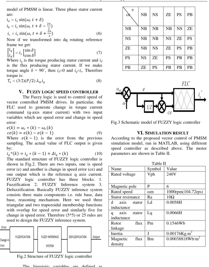
𝑖𝑞* 𝑘 = 𝑖𝑞∗ 𝑘 − 1 + 𝛥𝑖𝑞∗ (𝑘) (10) The standard structure of FUZZY logic controller is shown in Fig.2. There are two inputs, one is speed error (e) and another is change in speed error (ce) and one output which is the reference q axis current. FUZZY logic controller has three blocks. 1. Fuzzification 2. FUZZY Inference system 3. Defuzzification. Basically FUZZY inference system consists three main components i.e. rule base, data base, reasoning mechanism. Here we used three triangular and two trapezoidal membership functions with overlap for speed error and similarly five for change in speed error. Therefore (5*5) or 25 rules are used to design the FUZZY inference system.
Fig.2 Structure of FUZZY logic controller The linguistic variables are defined as {NB,NS, ZE, PS, PB} meaning negative big, negative small, zero, positive small and positive big. The FUZZY rules are summarized in Table I. The type of FUZZY interface engine is MAMDANI.
Table I e ce NB NS ZE PS PB NB NB NB NB NS ZE NS NB NB NS ZE PS ZE NB NS ZE PS PB PS NS ZE PS PB PB PB ZE PS PB PB PB
Fig.3 Schematic model of FUZZY logic controller
VI. S
IMULATION RESULTAccording to the proposed vector control of PMSM simulation model, run in MATLAB, using different speed controller as described above. The motor parameters are shown in Table II.
Table II Name Symbol Value Rated voltage Vph 240V Magnetic pole P 6 Rated speed ωm 1000rpm(104.72rps) Stator resistance Ra 10Ω d axis stator inductance Ld 0.0058H q axis stator inductance Lq 0.0066H Rotor flux linkage Pm 0.1546Wb Inertia J 0.00176Kg.m2 Magnetic flux density Bm 0.00038818Wb/m2
Fig.4 Current response curve for PI controller
Fig.5 Current response for FUZZY logic controller
Fig.6 id and iq for PI controller
Fig.7 id and iq for FUZZY logic controller
Fig.8 Speed response for PI controller
Fig.9 Speed response for FUZZY logic controller
Fig.10 Torque response for PI controller
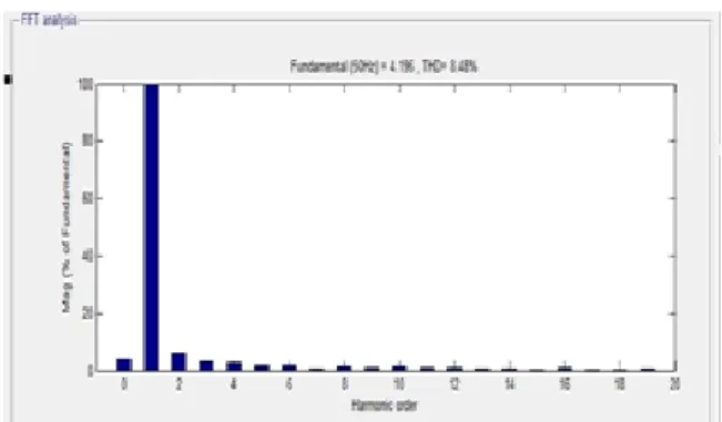
Fig.12 THD for the stator 3ɸ current for PI controller
Fig.13 THD for stator 3ɸ current for FUZZY logic controller
Table III comparison of controller performance PI FUZZY Speed
Rise time(tr) 0.0144 sec 0.0130 sec
Delay time(td) 0.0099 sec 0.00755 sec
Settling time(ts) 0.0257 sec 0.0176 sec Steady state error(ess) 3.46% 0.544% Torque ripple 29% 19.35% THD of Stator 3ɸ current 8.48% 6.29%
iq current 4.05 amp 4.4 amp id current 0 amp 0 amp
VII.
C
ONCLUSIONIn this work we made a comparison between PI and FUZZY logic speed controller in vector control of PMSM. From the above Table III we can see that by using FUZZY logic controller the transient response as well as steady state response of the motor speed is improved than PI controller for the load torque 𝑇𝐿= 3 N-M. And the steady state error is
very small in FUZZY logic controller. The torque ripple and THD of the stator 3ɸ current is improved in FUZZY logic controller. Therefore, from the above discussion we can conclude that the efficiency of the proposed FUZZY logic speed controller is improved rather than PI controller in controlling the vector control of PMSM. Here we set the simulation time is 0.1 second.
R
EFERENCES[1] Chen Junfeng, Permanent Magnet Motor[M], (Beijing, china Machine Press, 2002).
[2] Zhonghui Zhang and Jiao Shu, Matlab based Permanent Magnet Synchronous Motor Vector Control Simulation, IEEE,
978-1-4244-5540-9/10.
[3] Kaushik Jash, Prof. Pradip Kumar Saha and Prof. Goutam Kumar Panda, Vector Control of Permanent Magnet Synchronous Motor Based On Sinusoidal Pulse Width Modulated Inverter with Proportional Integral Controller, international Journal of Engineering Research and Applications,
ISSN : 2248-9622, Vol. 3, Issue 5, Sep-Oct 2013, pp.913-917.
[4] J. N. Lygouras, P. N. Botsaris, J. Vourvoulakis, V. Kodogiannis, Fuzzy Logic Controller Implementation for a Solar Air Conditioning System, Applied Energy 84,
vol. 20, pp. 1305-1318, 2007.
[5] A. G. Aissaoui, M. Abid, H. Abid, A. Tahour, A. K. Zeblah, A Fuzzy Logic Controller for Synchronous Machine, Journal of Electrical Engineering, vol. 58, pp. 285-290, 2007.
[6] Ì. Güney, Y. Oğuz, F. Serteller, Dynamic Behaviour Model of Permanent Magnet synchronous Motor Fed by PWM Inverter and Fuzzy Logic Controller for Stator Phase Current, Flux and Torque Control of PMSM, in Proc. IEMDC’01, pp. 479-485, 2001.
[7] M. Pradeep Kumar, S. Sirisha and M. Chandramouly, Design of Pmsm Base on Dtc method withMras, International Journal of Engineering Research and Applications,
vol. 1, issue 3, Sep-Oct 2013, pp. 646-653. [8] K K Pratap Singh, K V Bhargav and Ch.
Rambabu, Sensorless Speed Control of Surface PMSM using DTC Control Based on Extended Kalman Filter, International Journal of Engineering Research and Applications, vol. 3, issue 1, January-February 2013, pp. 1792-1796.