e-ISSN: 2278-067X, p-ISSN: 2278-800X, www.ijerd.com
Volume 11, Issue 01 (January 2015), PP.36-40
Visible Light Communication
1
Shweta Sagar,
2Deeksha Lal,
3Seema Dahiya
(1, 2,3Assistant Professor, HMRITM College (GGSIP University))
Abstract:- The aim of this paper is to determine the viability of Indoor Optical Wireless Communication System. This paper introduces Visible Light Communication along with its merits, demerits and applications. Then the main characteristics of VLC system are described, around which the project is designed. Multiple Input-Multiple Output (MIMO) technique is used in the project in order to enhance the data rate of transmission. Instead of using a system of only one LED and one APD, which transmits only one bit at a time, a system of 4 LEDs and 4 APDs is introduced, which increases the data rates by 300% from the previous case. We observe the signal, noise, SNR, BER etc. across the room dimension. Finally, in the last chapter we summarize our results on the basis of MATLAB simulations and propose some modifications to this model that can be implemented in future.
I.
INTRODUCTION
Optical wireless communication is a technology that uses light propagating in free space to transmit data for telecommunications or computer networking. The technology is useful where the physical connections are impractical due to high costs or other considerations.The first indoor optical wireless system was developed in 1979.This system used the infrared radiation which was spread in all directions. Such systems are called diffused infrared systems.The advancement of inexpensive opto-electronic devices, such as LEDs, P IN diodes and avalanche photo-diodes (APDs) and various optical components, has resulted in the improvement of these systems.
There are multiple access techniques which define the way that terminals can share the infrared medium simultaneously.Multiple access techniques can be classified into two types: optical and electrical Multiplexing techniques.Optical multiplexing techniques are Wavelength Division Multiple Access (WDMA) and Space-Division Multiple Access (SDMA).The electrical multiplexing techniques are Time -Division Multiple Access (TDMA), Frequency-Division Multiple Access (FDMA) and Code-Division multiple Access (CDMA).
Visible Light Communication (VLC also known as Optical Wireless Communication OR Free-Space Optics) is a technology, which is a result of the union of Optical Communication and Wireless Communication. Inthis communication system, LED/Laser Diodes acts as the transmitter and Photodiodes acts as thereceiver, which is same as that in optical communication. But instead of optical fibers, naturalatmosphere acts as the carrier.VLC can be used for wireless communications in certain areaswhere RF communications exhibits poor performance. The various merits of VLC over RF communication are like limited transmission power, regulated spectrum and also RF communication is banned in some areas.
VLC offers a very wide area of research and applications like position detection, intelligent supermart, intelligent transport system, image sensor communication, networking, audio applications and aesthetics.
II.
VISIBLE LIGHT COMMUNICATION (VLC)
VLC system has mainly three parts namely transmitter, receiver and channel. Every kind of light source can theoretically be used as transmitting device for VLC. However, some are better suited than others.The receiver consists of an optical element to collect and concentrate the radiation onto the receiver photo detector. This converts the radiation into photocurrent, which is then pre- and post-amplified before data recovery.Receivers typically employ either long pass or band pass optical filters to attenuate ambient light. Long passfilters can be thought of as essentially passing light at all wavelengths beyond the cutoff wavelength. They areusually constructed of colored glass or plastic, so that their transmission characteristics are substantially independent of the angle of incidence. Long pass filters are used in almost all present commercial infrared systems.
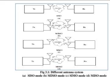
Fig 3.1: Different antenna system
(a) SISO mode (b) MIMO mode (c) SIMO mode (d) MISO mode
MIMO SYSTEM: We consider MIMO channels with NT transmit and NR receive antennas. The block diagram
of such a MIMO channel model is shown above.The channel matrix H is a complex matrix with
The component of the matrix H, hijis the coefficient of the each channel from the jth transmit antenna to the ith receive antenna.the normalization value of the channel matrix H, for a deterministic channel condition as follow,
If the channel coefficients are random, the normalization value will apply to the expected value. The received signal at ith receive antenna is given by
where, sj(t) is the transmit signal at jth transmit antenna and ni(t) is additive white Gaussian noise (AWGN) in the receiver with zero mean and 2 variance. In above equation, a transmit signal sj(t) from each transmit antenna is added to the signal of each receive antenna.
The capacity is defined as the maximum possible transmission rate when the probability of error is almost zero. The capacity of MIMO channel is defined,
𝐶 = max
𝑓 𝑠 𝐼 𝑠; 𝑦
Where, f(s) is the probability distribution function (PDF) of the transmit signal vector s and I(s;y) is the mutual information between transmit signal vectors s and receive signal vector y. The mutual information is given by
𝐼 𝑠; 𝑦 = 𝐻 𝑦 − 𝐻(𝑦/𝑠)
𝐼 𝑠; 𝑦 = 𝐻 𝑦 − 𝐻 𝑛 . (𝑦/𝑠)
For maximize the mutual information, I(s;y), reduces to maximizing H(y). Consequently, mutual information I(s;y) in equation is given by,
where, INRis an identity matrix, ES is the power across the transmitter irrespective of the number of antennas NT , RSS is the covariance matrix for transmit signal and the superscript H stands for conjugate transposition. From equation, the general capacity of the MIMO channel is
Applications of MIMO
Spatial multiplexing techniques make the receivers very complex, and therefore they are typically combined with OFDM where the problems created by a multi-path channel are handled efficiently. The IEEE 802.16e standard incorporates MIMO-OFDMA.
MIMO is also used in Mobile radio telephone standards such as recent 3GPP and 3GPP2. In 3GPP, High-Speed Packet Access plus (HSPA+) and Long Term Evolution (LTE)
In non-wireless communications systems. Eg: the home networking standard ITU-T G.9963, which defines
a power line communications system that uses MIMO techniques to transmit multiple signals over multiple AC wires (phase, neutral and ground).
MIMO AND VLC:In the application considered here each individual LED has very limited bandwidth, but there are many available for data transmission, but it is not possible to precisely align a detector and receiver array as the receiver moves around the coverage area. MIMO provides an opportunity to do this; we consider two ’limiting cases’ of receiver types. In the first an array of receivers, each with their own optical concentrator is considered, and in the second an imaging diversity receiver structure is used.
III.
PROJECT AIM
The aim of the proposed project was to simulate the Optical Wireless Communication (OWC) in the indoor settings. The main reasons for self-initiating this project:
1) The work in this domain has started not before 21st century. A lot of similar experimentations have been done but no experiment concentrated on dual application of LED for lighting and communication purpose in indoor setting.
2) The Visible Light Communication in indoor can be controlled easily. The noise components do not vary
appreciably and hence, can be simulated with reasonable success.
3) There is an amazing scope of increasing the data rate and reliability in indoor OWC using concepts like Optical Multiple Input Multiple Output (OMIMO), Wavelength Division Multiplexing (WDM), Orthogonal Frequency Division Multiplexing (OFDM), Spatial Modulation, Various Modulation schemes. Changing the technology of the components would also impact the performance of the system 4) The applications of this system are extremely versatile which ranges from broadband application, audio
music system, interactive technologies, networking.
5) The implementation of this system over the existing infrastructure is easily possible.
6) Just like CFLs replaced bulbs, LEDs are set to replace CFLs in the near future. The fast switching capability of LEDs places it uniquely for dual application of Lighting and Communication.
7) This technology can be integrated with Power Line Communication, which is another upcoming
development in communication arena.
IV.
PROJECT MODEL
Basic Structure:
With our first basic model, we intended to achieve visible light communication with the white LED light.
The design included only one white LED as the transmitter and only one photodiode as receiver.
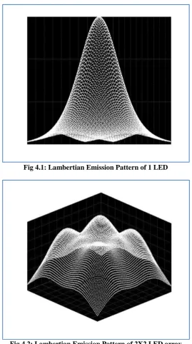
The LED would be programmed according to the lambertian pattern it displays.
The photodiode would be appropriately placed in order to sense the light coming from LED.
The next step was to replicate the process for multiple numbers, an array to be precise, of LEDs. The idea is to prepare base for MIMO system.
Fig 4.1: Lambertian Emission Pattern of 1 LED
Fig 4.2: Lambertian Emission Pattern of 2X2 LED array
After this basic work, we separated our project into two essential portions. The first portion of the project consisted of multiple LEDsand multiple APDs across the room, preferably but not necessary, in an array. The aim of this portion was showcase the phenomenal increase in the data rate transmitted without any compromise on the fidelity of communication. This model shows us the benefits of multiple input multiple output (MIMO) technique in enhancing the data rates.
V.
CONCLUSION
We have already seen, through our simulations, that optical wireless communication system is a very good replacement for the regular communication systems. The SNR and BER that we received from simulation corroborate this claim.
Fig 5.1: Room Matrix of SNR (in dB)
REFERENCES
[1]. Toshihiko Komine and Masao Nakagawa “Fundamental Analysis for Visible-Light Communication
System using LED Lights” IEEE Transactions on Consumer Electronics, Vol. 50, No. 1, FEBRUARY 2004.
[2]. Y. Tanaka, S. Haruyama and M. Nakagawa, “Wireless optical transmission with the white colored LED for the wireless home links, ”Proc. of the 11th Int. Symposium on Personal, Indoor and Mobile Radio Communications (PIMRC 2000), London, US, pp.1325-1329,2000.
[3]. F. R. Gfeller and U. Bapst, “Wireless in-house data communication via diffuse infrared radiation,” Proc. IEEE, vol. 67, no. 11, pp. 1474-1486, 1979.
[4]. A. P. Tang, J. M. Khan and K. P. Ho, “Wireless Infrared Communication Links Using Multi-Beam Transmitters and Imaging Receivers,” Proc. IEEE Int. Conf. on Communications, pp. 180-186, Dallas, TX, June 1996.
[5]. Talha A. Khan, Muhammad Tahir and Ahmad Usman “Visible Light Communication using
Wavelength Division Multiplexing for Smart Spaces”, Science, vol. 308, no. 5726, p. 1274, 2005. [6]. T. Komine and M. Nakagawa, “Fundamental analysis for visible-light communication system using
LED lights,” IEEE transactions on Consumer Electronics, vol. 50, no. 1, p. 100, 2004.
[7]. Kaiyun Cui, Gang Chen, ZhengyuanXu, and Richard D. Roberts, “Line-of-sight Visible Light
Communication”, vol. 16, no. 26,pp. 21835-21842, December 2008.
[8]. J. Grubor, S. C. J. Lee, K.-D. Langer, T. Koonen, and J. W.Walewski, “Wireless high-speed data transmission with phosphorescent white-light LEDs,” Proc. Post Deadline SessionEur. Conf. Opt. Commun. (ECOC 2007), Berlin, Germany, 2007, pp. 1-2.
[9]. JOSEPH M. KAHN AND JOHN R. BARRY, “Wireless Infrared Communications”, PROCEEDINGS
OF THE IEEE, VOL. 85, NO. 2, FEBRUARY 1997
[10]. Z. Wu, J. Chau, and T.D.C. Little,” Modeling and Designing of a New Indoor Free Space Visible Light