Design and Blade Optimization of Contra Rotation
Double Rotor Wind Turbine
Priyono Sutikno
1, Deny Bayu Saepudin
21Institut Teknologi Bandung, Bandung, Indonesia, [email protected] 2
Institut Teknologi Bandung, Bandung, Indonesia, [email protected]
Abstract-- The Intelligent Wind turbine (IWT) has two stages blades contra rotation. This kind of wind turbine has characteristic self regulated on the speed due to the difference torque between two stages horizontal axis wind turbine, than no need the pitch controller to control the speed and cut off the wind turbine due to the high wind speed.
The research of IWT is designed first by optimize several important design parameters, as a blade section profile and the multiplier factor of the angle of attack. The design parameter results are the NACA 6412 is selected as the optimum blade section profile and the optimum value of angle of attack multiplier factor is 0.5. The designed IWT has 3 blades for each front and rear rotor. The research intelligent wind turbine has 600 mm front diameter and 600 mm rear blade diameter. The characteristics of IWT were simulated by using Computational Fluid Dynamic (CFD) software, demonstrated the non entrainment of the contra rotation, each blades should have the same produced torque.
Index Term-– Intelligent Wind Turbine, Numerical S imulation, Contra rotation Wind Turbine
I. INTRODUCTION
The conventional wind turbines with large sized wind rotor generate high output in the moderately strong wind. The output of the small sized wind rotor is low such a wind rotor is suitable for weak wind. That is, the size of the wind rotor must be appropriately selected in conformity with potential wind circumstances. Besides, in general the wind turbines are equipped with the bra ke and or the pitch control mechanis ms, to control the speed due to the abnormal rotation and the overload generated at the stronger wind, and to keep the rotation of generator. In that sense, some studies present a good review of various invented the superior w ind turbine generator, T. Kane moto [1] has invented Intelligent Wind Turbine Generator (IWTG) co mposed of the large sized front wind rotor, the small sized rear wind rotor and the peculiar generator with inner and the outer rotational armatures, as the rotational speeds of the tandem wind rotor are adjusted pretty well in cooperation with the two armatures of the generator in response to the wind speed. The IWTG model is co mposed of tandem wind rotor using the flat b lades, and demonstrated the fundamentally superior operation of the tandem wind rotor. In this paper, the effect of the blade profiles using NACA profiles on the turbine using numerica l simu lation on the turbine performances are investigated to optimized the rotor profiles.
Nomenclature
A Area
a Axial induction factor
a’ Radial Induction factor B Number of blade CD Drag coefficient
CL Lift coefficient
c Chord length Cp Power Coefficient
D Diameter
Fx Axial Force
g Acceleration of gravity L Lift force
P Power
p pressure Q correction factor
r local radius element rotor Re Reynolds number
R Radius
T Torsi
T
ThrustVo Absolute Velocity
w Relative velocity u Tangential velocity x Local speed ratio
α angle of attack (AOA) β stagger angle
e Ratio coefficient Lift and Drag γ pitch angel
η Efficiency λ Tip speed ratio
ρ density
angle of attack relative σ SolidityΩ Angular velocity
II. OPERATION OF TANDEM WIND ROTORS
behaviour of the front and rear wind rotors also depends on the blade profiles and flow condition between both rotors, and will be d iscussed. The rotational direction and speed of the rotors are adjusted in response to the wind circu mstance (see fig. 2)
Fig. 1. Drawing IWT G [1]
Fig. 2. Operation of IWT G [1]
The authors has proposed the optimized blades with adopted the NACA Air foils for rear and front blades of the contra rotation wind turb ine. It is d ifficult, however to know the rotational torque but also to get optimized b lades profiles, using the contra rotation model. In order to elaborate and to get the optimized blades, the model was separated from tandem to single isolated wind turbine, however the rear turbine has the velocity data’s from the front wind turbine blade simulation.
III. AIR FOIL AND ROTOR PERFORM ANCE ANALYSIS
Airfo il has made rotor possible to rotate in high speed and load, early aerodynamics of wind turbine has based on theory of air p lane wings. Ho wever, aerodynamics of wind turbine has been required diffe rent idea, the accuracy of rotor performance analysis depend ma inly on the treat ment of the wake effect, because the wake of propeller type wind turbine is induced a large velocity in rotor plane. For Horizontal A xis Wind Turb ine blades the aviation a irfoils such as NACA series have been widely used. But these air foils have been recognized to be insuffic ient for require ments, such reduction of rapid stall characteristics, in-sensitivity to wide Reynolds number the range of between 5.105 to 2.106. Rotor performance analysis has been performed using several methods. The Blade Ele ment
Momentum (BEM) method is ma inly e mp loyed as a tool of performance analysis because of their simplic ity and readily imple mentation. Vorte x wa ke methods can adequately treat the effect of wa ke vortices and have some advantages over BEM.
3.1 Blade Element Momentum Method
Most wind turbine design codes are based on Blade Ele ment Mo mentum (BEM) method [7]. The basic BEM method assumes the blade can be analyzed as a nu mber of independent ele ments in span wise direction. The induced velocity at each element is determined by performing the mo mentu m balance for an annular control volume containing the blade ele ment. The aerodynamic fo rces on the ele ment are ca lculated using lift and drag coeffic ient fro m e mp irical t wo dimensional wind tunnel test data at the geometric angle of attack (A OA) of the blade ele ment relative to the local flow velocity.
BEM method have aspect by reasonable tool for designer, but are not suitable for accurate estimation of e ffect of wa ke, comple x flow such as three dimensional flo w or dynamic stall because of their assumption.
3.2 Vortex Wake Method
The induced velocity in the rotor plane of Horizontal Axis Wind Turbine (HAWT) is large ly increased in heavy loading condition and the wake vortices of HAWT develop to the downstream constructing highly skewed vorte x sheet in la rgely decele rated a xia l flow near rotor plane. Thus determination of the velocity induced by wake and wake geometry is one of the most important aspects in the rotor performance analysis.
Vo rte x wake method directly calculates the induced velocity fro m the bound vortices of blades and the trailing vortex in wake which are represented by liftin g line or lifting surface model [4]. The treat ment of wa ke geometry can be classified roughly into two type, as a prescribed wake model and free wake model. In the forme r mode l the wake represented by a line a vortex or spira l vortices with fixed pitch. In later one a fractional step scheme is adopted and the configurations of the wa ke are calcu lated at every t ime step using local veloc ity inc luding the co mponents induced by wake and bound vortices. The free wa ke model is generally tackled with vorte x lattice method which can fit on arbitrary blade shape with camber, taper and twist.
Another method of the vorte x wa ke methods is use of an asymptotic acceleration potential. Accelerat ion potential method is basis on the Laplace equation of pressure perturbation. The rotor b lades are represented in the model as discrete surfaces on which a pressure discontinuity is present. The model implies the presence of span wise and chord wise pressure distributions, which are composed of analytical asymptotic solution for Laplace equation. More elaborate model makes it possible to calculate the dynamics load caused by dynamic inflo w and yawed inflow situation [5].
3,3 Computational Fluid Dynamic
calculated aerodynamics of HAWT using RANS mode l and overset grids to facilitate the simu lation of flow about comple x configuration. Recently, so me CFD’s codes actively are developed of CFD analysis of rotor flow by three dimensional Navier Stokes code.
Though the state of the art CFD is needed considerable computer power and validation for Nav ier Stokes model, CFD has potential advantage for detailed understanding of aerodynamic of the HAWT.
IV. OPTIM AL ROTOR BLADE
4.1 The NACA series air foil
The design model, wh ich is composed of tandem wind rotor, designed based on Blade Ele ment Mo mentum (BEM) method. The design is used the 4 (four) d igit NACA a irfoil and to be chosen among 7 (seventh) airfoil profile as shown at fig. 3.
A : 1st digit is the percent of chord B : 2nd digit is the ten percent of the chord C : 3rd and 4th digit is the percent of chord
Fig. 3. Airfoil Profile of 4 digit s NACA XXXX
The criteria of NA CA airfoil to be imple mented to the front rotor and rear rotor, the XFOIL software is used to simu lated the Lift and Drag Coefficient at function of AOA, the criteria’s are
a. The airfoil has a good performance, should have as bigger as possible the ratio of the ratio the Lift and Drag coefficients as shown at Table I.
b. The section of the airfoil has simple fo rm possible, which has a flat suction in order to simply the blades manufacturing, see Fig. 3.
TABLE I
THE MAXIMUM LIFT AND DRAG RATIO OF NACA5 AND 6 SERIES
Beside the Lift and Drag Rat io, the ca mber to chord ratio can be influenced the Lift to Drag Ratio, and as shown at fig. 4. The NA CA airfo il has been chosen, have a certain AOA at the maximu m Lift to Drag Ratio.
The number of blades at the front and rear rotor depend on the velocity to tip rat io as shown at table II [5]. The rotation of the front and rear rotor depend on the tip speed ratio, for tip speed ratio between three and more than four, the number of rotor is three.
TABLE II
THE NUMBER OF BLADE DEP END ON SP EED TIP RATIO Λ
λ B [number of blade]
1 8 – 24
2 6 – 12
3 3 – 6
4 3 – 4
More than 4 1 – 3
The rotor performance analysis of IWT has been calculated by the model Actuator Disc and Blade Ele ment Mo mentu m. This method has been modelled and developed by Glauert (Ingra m, 2005), the inflo w near the rotational b lade or disc as the induced velocity in the rotor plane is large ly increased and represent by rotational inflow factor.
The aerodynamic forces on element are calcu lated using the lift and drag coefficient from XFOIL software.
Fig. 4. T he Lift to Drag ratio of the NACA XXXX series
The optimu m blade can be concluded by comparing the data on table I and performance of b lade in the fig. 1 and 4 with respect to the criterion above, the chosen blade has thickness to chord ratio of 12%, the ca mber to chord ratio is 6% and the air foil NACA 6412 is chosen as airfoil for front and rear rotor.
4.2 Opti mal r otor bl ade using GLAUERT-PRANDTL-XU model.
The calculat ion is based on the Blade Ele ment Momentum (BEM) method, this method is suitable for engineering development and there are two kind s of categories: fixed pitch and variables pitch rotor blade. The blade length is divided into several small ele ments for which the two dimensional airfoil theory can be applied. The dimensionless coeffic ient, CLand CD, the net force, power
For torque:
cos
BcΔc
D
C
sin
L
C
r
2
ρW
2
1
ΔQ
(1)For power:
cos
Bc
r
D
C
sin
L
C
r
2
W
2
1
Q
P
(2)For thrust:
sin
Bc
r
D
C
cos
L
C
2
W
2
1
T
(3)where
sin
u
W
=
cos
w
r
Fig. 5. Local element velocities and flow angles [8]
Based on actuator disc theory and Using dimensionless axia l
and radial induction factor,
0 0V
u
V
a
andr
w
'
a
andsolidity,
R
Bc
we find equation above became
Fig. 6. Local elemental forces [8]
2 D Lsin
sin
C
cos
C
r
8
R
a
1
a
(4)
1
a
'
a
'
8
R
r
C
Lsin
sin
cos
C
D
cos
(5)
Also we have
w
r
u
tan
'
a
1
r
a
1
V
0
x
1
a
'
a
1
(6)where, x = 0
V
r
, is local speed ratio. At the end of the
blades, r beco me R, and we find the most important parameter for wind turbine rotors, the tip-speed-ratio,
or
0
V
R
X
, using X, we canwrite,
'
a
1
a
1
rX
R
tan
, the two dimensional lift anddrag coeffic ients CL and CD are both function of angle of
attack
L D
C
C
, Instead of using the averagesolidity, it’s define a symbol called the blade loading
coefficient,
r
.
8
Bcc
l
, using
and
sin
cot
a
1
a
(7) And
1
a
'
a
'
tan
sin
(8) To obtain a single point optimu m including the effect of drag, deriving a local power coefficient [6],3 0 D L 2 3 0 2 1 ' P
V
2
)
cos
C
sin
C
(
Bc
W
A
V
P
C
(9)where,
C
sin
C
cos
Bc
dr
Ωr
ρV
ΩdQ
dP
L D2 to ta l 2
1
and dA =2 π dr by using :
2 2 2
22 2
total
U
1
a
r
1
a
V
and equation 6, thenequation 9 can be write
1
a
1
cot
4
xλ
sin
φ
ε
cos
C
p
2
2
(10)
Then, eliminating λ using equation 7 and expanding 1/(cot
+ ε) in a Taylor’s series of two terms, there results
1
a
tan
1
tan
xa
4
C
p
(11)Since the optimu m value of a is founded to be quite
insensitive to changes in ε, this imp lies that
C
p decreasesmonotonically as ε increases. By defining a local Froude efficiency (Eq. 12), we can relate the performance o f each blade element to the ideal value of unity [6].
p F
C
16
27
(12)good matched on HWAT (Horizontal A xis Wind Turbine) [10], the Prandtl tip correction factor is
1
2
cos
exp
7
tip tip tip
Q
f
if f
1
7
tip tip
Q
if f
(13)
2 sin
tip
B R r
f
r
And for hub correction factor can be written as
1
2
cos
exp
7
hub hub hub
Q
f
if f
1
7
hub hub
Q
if f
(14)
2
sin
hub hubhub
B r
R
f
R
Ea rly 2001, Xu proposed the correction factor on hub losses by using the Prandtl correction factor as written above and the Xu correction factor for hub can be written as
0,85
0,5
0,5
0,7
1
new
tip tip
r
Q
Q
if
R
(15)
1
/ 0,7
1
0.7
0, 7
tip r R new
tip
r
Q
r
Q
if
R
R
Flowchart in fig. 7 e xp lained the comp lete procedures of rotor turbine design. This flo w chart refers to optimu m design procedure of rotor blade and the source program is written in FORTRAN code, wh ile XFOIL is used to obtain the Lift coeffic ient and Drag coeffic ient of a irfo il data which is chosen for blade design. After obtaining the Lift and Drag Coeffic ients an interpolation is performed to justify Reynolds number and angle of attack (AOA) on calculat ion XFOIL or two dimensional flow over the airfoil by Fluent.
Fig. 7. Flowchart to calculate forces and power at the optimum performance
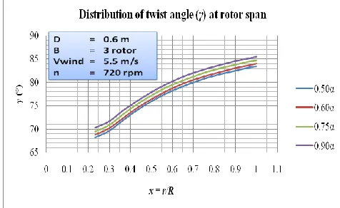
Fig. 8. Graphic of distribution of chord length and twist angle at rotor span
chord length and stagger angle in function of angle of attack (AOA).
Fig. 9 shown graphic of the torque and the efficiency curve versus the rotational speed and the fig. 10 shown graphic of the torque and efficiency versus rotational velocity results of the numerical simu lation using the FLUENT software. Fig. 11 shown graphic of the e fficiency as functions of the velocity source calculated manually and simu lated three dimensional numerically using the FLUENT.
Fig. 9. Graphic of torque versus rotational speed calculated and simulated numerically
Fig. 8 to 9 shown the graphics of chord length versus span length of rotor, the torque versus rotational speed and the efficiency versus rotational speed respectively, these result s has been calculated by PRANDTL-XU correction equation and simulated nu merica lly using the FLUENT 6.3.26. We
can concluded the optimu m performance is used the angle of attack with 0,6 to be chosen with regard of
The Ma ximu m effic iency is near of the working or design point at the rated rotation
The produced torque has relatively high
The values of the effic iency of the wind speed region (2 until 12 m/s) are a lways re latively h igh and stable as shown at fig. 11.
Fig. 10. Simulation result using the Blade Element Momentum and Prandtl_Xu correction factor on efficiency versus rotational speed
Fig. 11. T he efficiency versus wind speed
V. DESIGN AND SIM ULATION OF THE IWT
5.1Design Procedures for Wind Turbine Rotor
Flowchart in fig. 7 e xpla ined the co mplete procedures of rotor turbine design. This flowchart refers to optimu m design procedure of rotor b lade, and the source program is written in EXCELL code, wh ile the XFOIL or FLUENT software is used to obtain lift coeffic ient (CL) and drag
coeffic ient (CD) of airfo il data which is chosen for the blade
design. After obtaining the lift coeffic ient (CL) and drag
coeffic ient (CD), an interpolation is performed to justify
Reynolds number and angle of attack on calculation.
5.2 Simulation Pr oce dures for Intelligent Wi nd Tur bine Front and Rear Rotors
The simulation of Intelligent Wind Turbine front and rear rotors are using computational flu id dynamic (CFD) method through Fluent software. The simulation process consists in t wo parts, the two dimension model and three dimension models. Two dimension model is using FLUENT DDP to calculate lift coefficient (CL), drag coefficient (CD),
pressure coeffic ient and flo w characteristic through airfoil profile in two d imension, wh ile Fluent 3D is used to calculate force components which rotor produced and flow characteristic in three dimension, especially flo w behind the rotor which shown velocity decrease and wind energy, turbulence, and wake.
The two d imension simulat ion proposed to obtain airfoil characteristics which will be used in b lade design with angle of attack variation and Reynolds number variat ions, then served as an input on blade design by using interpolation. The airfoil profile has been calculated and simulated at section 4.
Two dimension simulat ion process is completed by Ga mbit meshing around 66.000 ce lls and iterat ion using FLUENT 2DDP with assumption of co mpressible flow and coupled solver was used including energy calculation using absolute velocity formulation in steady condition. These assumptions are requisite in order to obtain accurate current model on airfoil surface by showing turbulence phenomenon, flow separation, boundary layer, and reversed flow. Th is flow phenomenon is their natural flow characteristic, where the decreasing of whole airfo il performance and rotor effic iency in extreme situation [9].
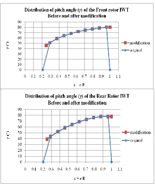
The result of calculat ion for the front and rear rotor can be shown as bellows:
Fig. 12. Result of distribution of chord length (c) of the front and rear rotor span of IWT
Fig. 14. T he front at the left fig. and rear rotor at the right
5.3 The three Di mensional Model Simulati on of the IWT front and rear rotor.
The analyzed aerodynamic proble m is flow detriment including wa ke a round rotor, distribution of ve locity and pressure decrease in axia l direction. The first simulat ion is made to a front rotor with 60 c m dia mete r which placed in a cylinder wind tunnel with 150 c m dia meter and 300 c m length. Flo w condition is steady, front rotor speed constantly at 600 rp m and t ip speed ratio of 3.142 wind condition for rear rotor can show at fig. 15.
Fig. 15. Position of the pickup velocities and pressures from the front rotor blade
directions are assumed uniform ve locity input before hits the rotor. The second simulation is made a rear rotor with 60 c m dia meter, the boundary condition of the input rear blade are the velocity vectors output from the first simu lation of the front blade. The pickup boundary
Three dimension wind turbine rotor is produced using 3D Inventor modeling progra m (Inventor 2008) version. Blade is made of several a irfoil profiles along the span using blend method to form blade with twist pattern, previously these airfo il profiles were kept in *.sec format. Afterwa rds, the blade ma king result that produced by Inventor 2008 are exported to Gambit in *.igs format.
Fig. 16. Intelligent Wind T urbine, the front and rear blades in isometric and front view
Front rotor
Axis of rotor Rotor axis
Blade 3 Blade 2
Modeling process in Ga mb it is making meshing around 6.0 million ce lls (T GRID) and defin ing boundary conditions. Modeling in Ga mb it taking the wind tunnel analogy as boundary conditions, and there is only one volume control around rotor asrotating fra me. In Fluent, the fin ishing process is using segregated solver model with relative ve locity formu lation or mu ltip le re ference fra mes (MRF) mode l and steady conditions . It is important to do the relative veloc ity formu lation because the volume control that used is rotating fra me (non inert ia) [2], in order to analyze relat ive velocity impact to a rotor and e xposed current flo w behind the rotor (wake ) [9]. The e xpected result in 3D simu lation is to get far flo w around rotor, not just only at the rotor surface. The applied viscous model is the same model that applied in 2D simulat ion wh ich is viscous k-ε model [8], [10].
VI. RESULT AND DISCUSSION
Two dimension and three dimension rotor turbine are analysis using optimu m blade design and calculated with BET PRA NDTL-XU methods or designed and simu lated by 3D Fluent indicates a good results and have same similitude. If we co mpare both analyses result by fluent and by BET PRA NDTL-XU methods, it turned out that there is only small d ifference on ca lculation results of resultant velocity. It is showed by calculation result of velocity resultant distribution along the blade shown at fig. 9 and 10, where the torque is 17 Nm and the effic iency is 35% at 500 rp m and by using numerical simu lation Fluent, the torque is 0.14 Nm and the effic iency is 30% at 500 rp m. The sa me way the efficiencies calculated by both methods has a same tend.
Fig. 17. Simulation result of the torque and efficiency curve of the front and rear rotor IWT
The BET -PRANDTL-XU method has been used for the front and rear rotors optimu m design condition and produced the front and rear rotor blades as shown at fig. 14 above. The numerical simulat ion used FLUENT to get the performance shown at fig. 17 is the numerica l simulat ion result give the torque and the effic iency curves in function of rotation speed of the both rotor, front and rear rotor blades. The simu lation is conducted by s eparate the front rotor as a single wind turbine. To get the result of rear rotor numerical simu lation, the boundary condition should be setup from the output of the front rotor numerica l simu lation. The boundary condition for the rear rotor has been taped as shown at fig. 15, there a re several pic k up data’s in the radial direction and data’s at direction of flow in the upstream and downstream as we can see at z1, z2 and
z3. The p ickup data at radia l d irection are indicated by raw r1
until r5. The 3 dimensional IWT design can be seen at fig.
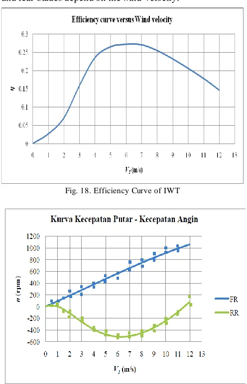
16, the front rotor has 3 blue blades and the rear blade rotor has green color. The result of nu merical simulat ion using the FLUENT has results as shown at fig.18, the effic iency curve of IWT versus wind velocity and fig. 19 shown the characteristic of the rotational velocity relative of the front and rear blades depend on the wind velocity.
Fig. 18. Efficiency Curve of IWT
Fig. 19. IWT Rotational speed versus wind speed
1.Blade pitch controlled wind turbine
2.Stall controlled wind turbines; passive stall controlled wind turbines and active stall controlled
On the Intelligent Wind Turbine (IWT) with contra rotation rotor blades has speed adjustment depend on the wind speed as shown at fig. 17. The IWT both rotors start to rotate at low wind speed, namely cut in wind speed, but the rear rotor contour rotates against the front rotor. The increase of the wind speed ma ke the both rotational speeds increase, and the rotational speed rear rotor become faster than that of the front rotor. At wind speed of 4 m/s the rotational of front rotor is 400 rp m and rotational speed of rear rotor is -400 rpm and until wind speed of the 6 m/s, the rotational of front rotor is 600 rp m and rotation of rear rotor is -500 rp m, that means the relative rotational velocity is 1100 rp m and IWT has maximu m efficiency of 27%.
At the wind speed more than 7 m/s, the rotational speed of rear rotor decreased until the wind speed 11.5 m/s, the rotation speed direction of both rotor, front and rear rotors has a same direction but the relative rotational speed remain same is 1100 rpm.
VII. CONCLUSION
The IWT which composed of tandem rotors and contra rotation has characteristic superior as the conventional wind turbine, than no need pitch control or stall control to controlling the rotational speed when wind speed became too high. The IWT can start rotate on weak wind speed. At moderate wind speed IWT can rotated relatively on adequate rpm, because the IWT has contra rotation rotor. When the wind speed increased, the relative rotational speed re main constant, event at high wind speed the relative rotational speed rema in constant about 1100 rp m, the rear rotor has been entrainment by the front rotor and rotated at same direction.
The numerical simulat ion was de monstrated the direction of the rotation of both front and rear rotor should have a same order torque. The method to get the optimu m blade profile and the nume rica l simu lation can be used as prelimina ry design and to get the estimated characteristic of contra rotation blade span.
ACKNOWLEGM ENT
This works was supported by Riset Unggulan 2010 LPPM (Research and Service to the Co mmunity Institute) INSTITUT TEKNOLOGI BANDUNG.
REFERENCES
[1] Toshiaki Kanemoto. and Ahmed Mohamed Galal. 2006. Development of Intelligent Wind T urbine Generator with T andem Wind Rotor and Double Rotational Armatures, Series B, Vol. 49 No 2, JSME International Journal.
[2] Dahl K. S., et al., Experimental Verification of the new RISO-Al Airfoil family for wind turbine, Proc of EWEC’99, 1999, pp 85-88 [3] Wilson, R.E., and Lissaman, P.B.S., Applied Aerodynamics of Wind Power Machine, NTIS PB 238594, Oregon State University, 1974
[4] Afjeh, A.A., and Keith Jr. T.G. A Vortex Lifting Line Method for the analysis of Horizontal Axis Wind T urbine. Transaction of ASME, Journal of Solar Energy Engineering, Vol. 108, 1986, pp. 303-309
[5] Hasegawa Y., et al., Numerical Analysis of Yawed Inflow Effect on a HAWT Rotor. Proc. of 3rd ASME/JSME. Joint Fluid Engineering Conference FEDSM 99-7820. 1999.
[6] Duque, E.P.N., et al., Navier-Stokes Analysis of T ime Dependent Flow about Wind T urbine, Proc. Of 3rd ASME/JSME Joint Fluid Engineering Conference, FEDSM99-7814, 1999.
[7] Priyono Sutikno, Numerical Optimization of Wind turbine blades.
Proceedings of the International Conference on Fluid and Thermal Energy Conversion 2003.
[8] Verdy Kohuan, Priyono Sutikno., Aerodynamic Design and Analysis of Wind T urbine Blade Propeller Type with Power 500 kW, Proceedings of the International Conference on Fluid and Thermal Energy Conversion 2006, FTEC 2006, Jakarta, Indonesia, December 10 – 14, 2006, ISSN 0854 – 9346
[9] Moriarty P., Hansen A., (2005). Aero Dynamic Theory Manual,
![Fig. 1. Drawing IWTG [1]](https://thumb-us.123doks.com/thumbv2/123dok_us/1392096.1650552/2.596.49.251.155.446/fig-drawing-iwtg.webp)

![Fig. 5. Local element velocities and flow angles [8]](https://thumb-us.123doks.com/thumbv2/123dok_us/1392096.1650552/4.596.44.277.65.397/fig-local-element-velocities-flow-angles.webp)