VOLUME 3, ISSUE 8, Aug. -2017
PERFORMANCE EVALUATION AND COMPARATIVE ANALYSIS OF
MIRROR AUGMENTED, 2D AND 3D COMPOUND PARABOLIC
CONCENTRATOR BASED PV SYSTEMS
J H BHANGALE
Department of Mechanical Engineering Matoshri College of Engineering and Research Center Nashik, India
H M DATE
Department of Mechanical Engineering Matoshri College of Engineering and Research Center Nashik, India
ABSTRACT:
In this present work, the performance
evaluation and comparison between mirror
augmented silicon PV panel system, 2D CPC based silicon PV panel system and 3D compound parabolic concentration for a simple poly-crystalline silicon solar cell of area 10 x 10 mm is examined. We compared all the three systems in view of productivity increment aspect for different inclination angles from ground horizontal surface ranging. The percentage increment in power output found in case of 3D compound parabolic concentrator is maximum of all the above mentioned systems i.e, 23% for 280. As the
solar cell temperature increases, its efficiency reduces. Thus, to keep the solar cell temperature within prescribed range and also to make maximum utilization of the heat received by the sun, a thermal heat exchanger unit is installed at the back of solar panel which extracts the heat from solar cells; thereby
maintaining the solar cell temperature of 250. The
thermal performance in terms of efficiency achievement for utilization of heat available is evaluated for all above three systems. 3D CPC based system found the best with heat conversion efficiency ranging up to 46%
KEYWORDS: Compound parabolic concentrator, mirror augmentation of solar panel, solar cell concentration, non-imaging techniques, solar energy, CPC, solar efficiency, solar heat exchangers.
I. INTRODUCTION:
The global need for energy is constantly increasing and makes it inevitable to reinforce the use of alternative resources. The sun is one of the richest energy sources in this context and is almost inexhaustible. Energy efficiency and solar technology are important elements to any building or community design. Also, they are important to the nation and to the Earth. The Sun is a massive reservoir of clean energy and the power from the sun's rays that reach the earth is called as solar energy. Solar energy is the most readily available source of energy. Solar energy received in the form of radiation can be converted directly or indirectly into other forms of energy such as heat and electricity which can be utilized by the man. Currently, the
installed capacity of solar projects in India is about 4.22 GW. India is planning to produce 100 GW of solar power by 2022. Considering the fact that solar cell efficiency degrades by 3% in a first year and less than 1% per year after that, a special attention must be provided to make effective utilization of such a huge solar installed capacity. In the present work, we have compared different non imaging cost effective solar energy harnessing techniques to judge their effectiveness. The mirror augmented system and 2D compound parabolic concentrator system are used for carrying out experimentations on poly crystalline silicon PV panel. Due to design constrains, experimentation is carried out on a single poly-crystalline silicon solar cell in case of 3D compound parabolic concentrator system.
II. TYPESOFCONCENTRATORS:
A. MIRROR AUGMENTATION SYSTEM:
The mirror augmentation of photo-voltaic panels is a cost effective way of increasing the electrical energy output of the panel. The general idea is to increase the solar energy that reaches the panel by adding a number of mirrors around it. If the mirrors are correctly positioned, a bigger percentage of solar rays will reach the panel, and therefore its effective area, i.e. its solar exposition area, will be increased.
VOLUME 3, ISSUE 8, Aug. -2017
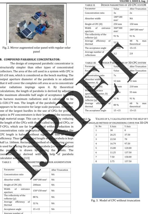
Fig. 2. Mirror augmented solar panel with regular solar panel
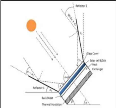
B. COMPOUND PARABOLIC CONCENTRATOR:
The design of compound parabolic concentrator is structurally simpler than other types of concentrated collectors. The area of the cell used in a system with CPC is 10 x10 mm, which is considered as the bench marking. The output aperture diameter of the parabola is so adjusted that it will cover the complete cell area so as to concentrate solar radiations impinge upon it. By theoretical calculations, the length of parabola is derived by adjusting the maximum allowable half angle of acceptance in order to harness maximum radiations and is calculated to be L=328.179 mm. The length of the parabolic concentrator appears to be excessive for large scale purposes. However, one of the largest hurdles in the use of CPCs for primary optics in PV concentrators is their length and the necessary high material usage. This can in part be offset by reducing the length of the CPCs with the so called truncated CPCs, or T-CPCs, which use far less material without reduction in concentration ratio and optical efficiency. In practice the CPC length is halved, without significant loss of optical efficiency. Thus the truncated length of the parabola is kept half i.e. 160mm. Rectangular method of engineering curves is used for tracing the points of parabola (co-ordinates)and the parabola is drawn by joining the points. The coordinates are derived with the help of parabola calculator software.[13]
TABLE I. DESIGN PARAMETERS OF MIRROR AUGMENTATION SYSTEM
Parameter Value After Truncation
Concentration ratio 1x NA
Absorber width 180*180 mm2 NA
Height of CPC (H) 200mm NA
Width of entrance
aperture 150*150 mm2 NA
The reflectivity of the
reflector (ρ) 88 % NA
Average efficiency of
thermal 32 % NA
Acceptance angle 15 +15 NA
Average number of
reflections 1 NA
TABLE II. DESIGN PARAMETERS OF 2DCPC SYSTEM
Parameter Value After Truncation
Concentration ratio 3x 2x
Absorber width 180*180
mm2 NA
Height of CPC (H) 250 mm 150 mm Width of entrance
aperture
300*300
mm2 280*280 mm2
The reflectivity of the
reflector (ρ) 91 % 91 %
Average efficiency of
thermal 52 %
48 % max theoretical The acceptance angle 15 +15 15+15 Average number of
reflections 3.2 2.8
TABLE III. DESIGN PARAMETERS OF 3DCPC SYSTEM
Parameter Value After Truncation
Parameters Value After Truncation
Concentration ratio 7x 5x
Absorber width
(diameter, d) 12 mm 12 mm
Height of CPC (H) 328 mm 210 mm Width of entrance
aperture (diameter, D) 65 mm 55 mm Reflectivity of the
reflector (ρ) 91 % 91 %
Average efficiency of
thermal 80 %
68 % max theoretical The acceptance angle 15 +15 15+15
TABLE IV. VALUES OF X, Y CALCULATED WITH THE HELP OF THE RECTANGULAR METHOD OF ENGINEERING CURVE FOR 3DCPC
Sr. No X Axis Y Axis
1 30 0
2 26.25 37.50
3 22.50 70
4 16.79 97.50
5 15.00 120.00
6 11.25 137.50
7 7.50 150.00
8 3.75 157.50
VOLUME 3, ISSUE 8, Aug. -2017
Fig.4 Model of truncated CPC by taking input aperture diameter as 12mm
III. EXPERIMENTALWORK:
This chapter includes the layout of experimentation, the details of instrumentation used with individual specifications.
The 3D compound parabolic concentrator is mounted on the photovoltaic cell at a fixed angle as the system is non-tracking and the readings are taken during the clear sunny day time. The layout of the experimentation is shown in the figure 8. It consists of a parabolic concentrator, poly crystalline silicon solar cell, wooden stand for mounting the cell, temperature sensor, sun meter, watch, multimeter, electric cables and resistance board. The Setup is placed under the sunlight and the readings are noted with and without concentrators from 10 am to 4 pm, with 30 minutes interval. The sunlight passing through CPC is concentrated onto solar cells. The junction of the solar cell is connected to the ammeter and the voltmeter through the resistance and the readings are taken.
In case of mirror augmentation system and 2D CPC based system, same method is followed for noting the readings of PV and thermal unit.
Fig. 5 PV collector performance evaluation without use of concentrators
Fig.6 PV collector performance evaluation for 2D CPC based system
Fig. 7 Layout of Test setup for 3D Compound Parabolic Concentrator
Fig.8 Experimentation setup for 3D CPC based system
The main components of the setup are as follows.
The solar photovoltaic cells with concentrators.
The temperature measurement system- thermometers, k type thermocouples.
The current and voltage measurement system (DMM)
The solar radiation measurement system- Sun-meter
The data acquisition system (sun simulator), data logger
Considering efficiency and productivity aspect, experimentation is focused on following three main data collection fields.
1. Result of I-V curve of sun simulator.
2. Result of actual performance of Mirror augmentation system and designed unit parabola with solar cell system under natural atmospheric conditions.
3. Optical performance of designed parabola.
VOLUME 3, ISSUE 8, Aug. -2017 by incorporation of a thermal unit. Thus the heat extracted
results in cooling of the photovoltaic panels which further can be utilized in space heating applications.[6]
IV. RESULTANDDISCUSSION:
Experiments are carried out for solar cell panel, with and without concentrators; for Mirror augmentation system and 2D CPC based system. In case of 3D CPC based system, single solar cell is tested with and without 3D CPC. The following results are obtained with the experimental analysis which is ultimately used for comparison between regular solar cell with compound parabolic concentration system and mirror augmented PV system. The results are shown in the tabulated form and the variation in temperature; time and intensity are represented graphically.
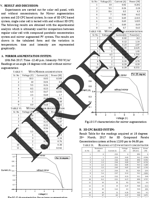
A. MIRROR AUGMENTATION SYSTEM:
10th Feb 2017, Time -12.40 p.m , Intensity-700 W/m2 Readings at an angle 18 degrees with and without mirror augmentation
TABLE V. WITH MIRROR AUGMENTATION Sr. No Voltage (V) Current (A) Power (W)
1 10.3 0.03 0.309
2 10 0.04 0.4
3 9.5 0.26 2.47
4 8.5 0.53 4.505
5 6.5 0.67 4.355
6 2.5 0.68 1.7
7 2 0.68 1.36
8 1 0.68 0.68
9 0.9 0.68 0.612
TABLE VI. WITHOUT MIRROR AUGMENTATION Sr. No Voltage (V) Current (A) Power (W)
1 10 0.02 0.2
2 9.6 0.13 1.248
3 9 0.23 2.07
4 8.2 0.32 2.624
5 7 0.36 2.52
6 5.5 0.38 2.09
7 5 0.38 1.9
8 3 0.38 1.14
9 2 0.38 0.76
10 1 0.38 0.38
11 0.9 0.38 0.342
Fig.9 I-V characteristics for mirror augmentation
Readings at angle 25 degrees with and without mirror augmentation
TABLE VII. WITH MIRROR AUGMENTATION Sr. No Voltage (V) Current (A) Power (W)
1 10 0.02 0.202
2 9.5 0.24 2.28
3 8.6 0.5 4.3
4 7 0.66 4.62
5 3.5 0.69 2.415
6 1.5 0.69 1.035
7 1 0.69 0.69
8 0.9 0.7 0.63
TABLE VIII. WITHOUT MIRROR AUGMENTATION Sr. No Voltage(V) Current(A) Power(w)
1 10 0.02 0.2
2 9.5 0.12 1.14
3 9 0.23 2.07
4 7.5 0.35 2.625
5 5 0.39 1.95
6 4.5 0.39 1.755
7 3 0.39 1.17
8 2 0.39 0.78
9 1 0.39 0.39
10 0.9 0.39 0.351
Fig.10 I-V characteristics for mirror augmentation
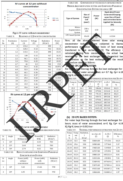
B. 3D CPC BASED SYSTEM:
Result Table for the readings acquired at 18 degrees on 20th March, 2017 for 3D Compound Parabolic Concentration system at from 12.00 pm to 04.00 pm
TABLE IX. READINGS AT12 PM WITHOUT CONCENTRATOR
Sr. No
Resistance
(Ω) Current (I)
Voltage (V)
Radiation (W/m2)
Power (W)
1 0 25.5 0 890 0
2 1 25.3 0.02 912 0.506
3 1.2 24.6 0.02 898 0.492
4 1.5 24.4 0.03 917 0.732
5 2.2 24.1 0.05 914 1.205
6 3.3 24.9 0.07 927 1.743
7 4.7 24.4 0.1 924 2.44
8 5.6 23.7 0.12 912 2.844
9 6.8 23.2 0.15 911 3.48
10 8.2 22.1 0.17 898 3.757
11 10 22 0.2 922 4.4
12 15 19 0.27 928 5.13
13 20 16.2 0.3 918 4.86
14 30 12 0.35 933 4.2
15 47 8.3 0.37 938 3.071
16 56 7 0.38 934 2.66
0 2 4 6 8 1
0. 0.1 0.2 0.3
0.4 0.5 0.6 0.7 0.8
Current (A)
Voltage (V)
For 25 degree with mirror
without mirror
0 2 4 6 8 1 1
0. 0.1 0.2 0.3 0.4 0.5 0.6 0.7
Current (A)
Voltage(V)
For 18 degree with mirror
VOLUME 3, ISSUE 8, Aug. -2017
Fig.11 IV curve without concentrator TABLE X. READINGS AT 12PM WITH CONCENTRATOR
Sr. No Resistance (Ω) Current (I) Voltage (V) Radiation (W/m2)
Power (W)
1 0 153.2 0 890 0
2 1 120.2 0.12 912 14.42
3 1.2 115.5 0.13 898 15.01
4 1.5 109 0.15 917 16.35
5 2.2 94.1 0.21 914 19.76
6 3.3 79.8 0.25 927 19.95
7 4.7 66 0.3 924 19.8
8 5.6 59.3 0.32 912 18.976
9 6.8 52.5 0.34 911 17.85
10 8.2 46.1 0.36 898 16.596
11 10 41.1 0.37 922 15.207
12 15 29.4 0.42 928 12.348
13 20 23.1 0.44 918 10.164
14 30 15.9 0.46 933 7.314
15 47 10.6 0.48 938 5.088
16 56 9 0.48 934 4.32
Fig.12 IV curve with concentrator
TABLE XI. RESULTS OBTAINED FOR MIRROR ARGUMENTATION SYSTEM
Sr no
Angle Power(W) Without mirror
Power(W) With mirror
Radiation (W/m2)
1 180 2.62 4.50 700
2 250 2.60 4.62 700
3 300 2.79 4.42 700
TABLE XII. RESULTS OBTAINED FOR COMPOUND PARABOLIC CONCENTRATION SYSTEM
Sr no
Angle Power (mW) without concentrator Power (mW) with concentrator Radiation (W/m2)
1 180 5.22 21.66 990
2 280 6.35 23.45 992
TABLE XIII. COMPARISON OF THE RESULTS OBTAINED FROM MIRROR ARGUMENTATION SYSTEM AND COMPOUND PARABOLIC
CONCENTRATION SYSTEM FOR ANGLE 180
Type of System
Size of Panel/ Cell (mm2)
Power (W)
Equivalent Power Generated Keeping
same Size of Panel and correction factor Applied for Intensity
(W) Mirror
Augmentation System
200 x
200 4.50 4.50
CPC based System
10x10 21.66 x 10⁻³ 6.1264
Now, all the above referred three solar energy concentrator techniques are subjected to thermal performance evaluation on the basis of heat energy transferred to heat exchanger. [2] The efficiency is calculated taking into consideration the actual heat received by the heat exchanger and theoretical heat concentration on the heat exchanger and the results obtained are stated as follows:
(a) 3D CPC BASED SYSTEM:
For water kept flowing through the heat exchanger for 5 hours, mass of water accumulated, m= 0.7 Kg, Cp= 4.186 KJ/Kg0K, Area A= 0.000121 m2
TABLE XIV. THERMAL PERFORMANCE ESTIMATION FOR 3D CPC Temp in 0C Temp out 0C Radiation, I W/m2
m x Cp x dt (J)
A xTx I (J)
Efficiency % 25.9 26.1 890 586.04 1938.42 30.23 25.5 25.8 980 879.06 2134.44 41.18 25.83 26.1 950 791.15 2069.10 38.23 25.41 25.7 961 849.76 2093.06 40.59 26.6 26.9 935 879.06 2036.43 43.16 25.5 25.86 853 1054.87 1857.83 56.77 26.3 26.7 944 1172.08 2056.03 57.01 25.5 26 972 1465.10 2117.02 69.21 25.8 26.1 956 879.06 2082.17 42.22
(b) 2D CPC BASED SYSTEM:
For water kept flowing through the heat exchanger for 5 hours, mass of water accumulated, m=2 Kg, Cp= 4.186 KJ/Kg0K, Area A= 0.0324 m2
TABLE XV. THERMAL PERFORMANCE ESTIMATION FOR 2D CPC Temp in 0C Temp out 0C Radiation, I W/m2
m x Cp x dt (J)
A xTx I (J)
Efficiency %
VOLUME 3, ISSUE 8, Aug. -2017
(c) SOLAR AUGMENTATION BASED SYSTEM:
For water kept flowing through the heat exchanger for 5 hours, mass of water accumulated, m=2 Kg, Cp= 4.186 KJ/Kg0K, Area A= 0.0324 m2
TABLE XVI. THERMAL PERFORMANCE ESTIMATION FOR MIRROR AUGMENTATION SYSTEM
Temp in 0C
Temp out
0C
Radiation, I W/m2
m x Cp x dt (J)
A xTx I (J)
Efficiency %
25.27 29.56 958 35915.88 558705.6 6.43
24.9 28.55 970 30557.80 565704 5.40
23.28 29.3 985 50399.44 574452 8.77
25.68 26.36 845 5692.96 492804 1.16
24.9 28.96 855 33990.32 498636 6.82
25.33 29.32 879 33404.28 512632.8 6.52
25.5 31.2 890 47720.40 519048 9.19
25.7 27.34 876 13730.08 510883.2 2.69 26.3 28.4 754 17581.20 439732.8 4.00
29 32.3 766 27627.60 446731.2 6.18
V. CONCLUSION:
We proposed a performance evaluation and comparative analysis of compound parabolic concentrator and mirror augmented solar panel. Our goal is to make available more solar radiations to impinge the solar cell area resulting in more energy output by the cell. We observed more output delivered with the use of Compound Parabolic Concentrator at the angle of inclination 280 but the system seems more costly as compared to mirror augmentation system. Mirror augmentation system is observed to be simpler and cost effective with little low productivity. We could get percentage increment in power output of 13% if mirror augmentation is done at an angle 250. We found Compound Parabolic Concentrator system costlier but more effective at ray tracing and actual performance. The percentage increment of energy output in case of CPC system is found 21% for 180 and 23% for 280. The above setup can be arranged in an array of concentrators as per power requirements so as to trap the external light to cover a large solar cell area.also thermal energy collected in mirror augmentation and 2D CPC is low compared to 3D CPC. From the data collected 3D CPC is more effective for better utility of solar energy and highest possible electric and thermal collection.
We demonstrated the effect of heat exchanger on all above mentioned three thermal concentration systems and in view of harnessing extra energy available in the form of solar cell temperature by subjecting the three systems for thermal performance evaluation. The results obtained for the actual thermal performance of the system is compared with the theoretical performance of the system and the efficiency for all the systems is calculated. We found that the thermal performance efficiency in case of 3D CPC system as solar cell is placed on copper heat exchanger;
heat transfer rate is high as compared with 2D CPC based system and mirror augmentation system. It is also observed in case of 3D CPC that the theoretical useful heat conversion between solar cell and the water is around 46%.
REFERENCES:
1) S. Tselepis and Y. Tripanagnostopoulos,2002,
Economic analysis of hybrid Photovoltactic /thermal systems and comparison with standard PV module”.
2) Mohd..Yusof othman, Baharudin Yatim, 2008,
“Performance Analysis Of A Hybrid
Photovoltaic-Thermal Solar Air Heater”, 2nd WSEAS/IASME,Corfu,
Greece.
3) Ibrahim Yakube Tsoho,HAsan,Nawawi Yahya,Musa Momoh,2015, “Design and Construction of a Thermosiphonic Solar Photovoltaic-Thermal Water
Heating System”.Journal of Applied
Physics,2278-4861.Volume 7, Issue 2 Ver. II (Mar. - Apr. 2015), PP 88-96.
4) Husai Matsuoika,2016,“Design and evaluation of thermal - photovoltaic hybrid power generation module
for more efficient use of energy”,NTT Docomo Technial
Journal,Vol.12.382-40.
5) ansi G. Sheth and Prof. Amitkumar Thakur ,2014,
“Development of 2d compound parabolic concentrating solar collector for its different surface temperature analysis”, ISSN Vol. 2,No.1,pp 321-324.
6) Singiresu S. Rao, Hoe-Gil Lee and Yi Hu ,2014, “Optimal Design of Compound Parabolic Concentrator Solar
Collector System”, ASME Vol. 136,pp 348-358.
7) Lun Jianga, Roland Winstona,2014, “Progress on
integrated compound concentrator design“,Energy
Procedia Vol 48,pp 114 – 122.
8) Siti Hawa Abu-Bakar,Firdaus Muhammad-Sukki, Roberto Ramirez-Iniguez, Tapas Kumar Mallick, Abu Bakar Munir, Siti Hajar Mohd Yasin and Ruzairi Abdul Rahim,2014, “Rotationally asymmetrical compound parabolic concentrator for concentrating photovoltaic
applications”, Applied Energy Vol 136, pp 363–372.
9) R. Oommen and S. Jayaraman,2001, “Development and Performance analysis of Compound Parabolic solar concentrators with reduced gap losses oversized reflector”, Energy Convers. Mgmt Vol. 42, No. 13, pp. 1379-1399.
10)Yong Kim, GuiYoung Han and Taebeom Seo ,2008, “An evaluation on thermal performance of CPC solar collector”, Heat and Mass Transfer. Vol 35,pp. 446-457. 11)A.R. El Ouederni1, M. Ben Salah, F. Askri, M. Ben Nasrallah, F. Aloui,2009, “Experimental study of a parabolic solar concentrator”, Energies Renouvelables Vol. 12 N°3 (2009) 395 – 404
12)S Senthilkumar, K Perumal and P S S Srinivasan,2009,
three-VOLUME 3, ISSUE 8, Aug. -2017
dimensional compound parabolic concentrator for spherical absorber”, Vol. 34, Part 3, pp. 369–380 13)S.Senthilkumar, N.Yasodha,2012. “Design and
Development of a Three Dimensional Compound Parabolic Concentrator and Study of Optical and
Thermal Performance” IJES Vol.2 ,No.2, PP.64-68.