s Z
R
esearch
A
rticle
DESIGN AND IMPLEMENTATION OF FORWARD ERROR CORRECTION IN FPGA AND
VERFICATION
1,*
Sunil Prasad, N. and
2Saketh, M.
1
Department of Electronics and Communication Engineering, Sri Ramakrishna Institute of Technology
Coimbatore, Tamilnadu, India
2
Communication System Division, SAMEER-Centre for Electromagnetics, IWMS campus, Perungudi, Chennai,
Tamilnadu, India
ARTICLE INFO ABSTRACT
Quadrature modulation systems are used in satellite communication. I and Q are two channels which are represented in modulated signals. One of the schemes of Quadrature modulation is offset Quadrature Phase Shift Keying. Quadrature Phase Shift Keying produces the phase ambiguity in carrier recovery process which can be eliminated with OQPSK.Also OQPSK ensures high speed transmission in optical Networks. Due to more requirements of the radio channels, spectral effective modulations are intended to diminish spectral overload of communication systems. One such methods of modulation is offset QPSK. Forward Error Correction (FEC) is proposed in this paper for the OQPSK transmitter. Convolutional encoders are used in FEC for the process of encoding. FEC is technique that introduces redundancy to allow correction of error. Forward error correction is achieved by using convolution method. FEC technique is used in audio and video applications.The convolutional encoder with half the rate of input data stream and constraint length k=3 & k=7 are designed and corresponding source codes are generated. The source codes for the two encoders are programmed using MATLAB and VHDL. The outputs of MATLAB source code is used for comparison analysis of VHDL source code outputs. MATLAB is mainly used to check the functionality of the encoder. The convolution encoders are generated using MATLAB and VHDL code and their outputs are verified.
INTRODUCTION
The process of transmission mainly includes encoding and modulation. As Communication systems play a major role in the informational revolution, communication systems have reached extremely high data rates. The channel coding is used for this purpose. A redundancy bits are added to ensure that any error occurs during transmission. Channel coding is the most commonly used technique for encoding. One such a coding is Forward Error Correction (FEC). There are two types in FEC which are block codes and convolutional codes. Convolutional codes are widely used in encoders because it is advantageous than other coding technique. IS-95, A Wireless Cellular Standard for CDMA, employs convolution coding which is the part of convolution coding because FEC is suited to a channel in which the transmitted signal is corrupted because of additive white Gaussian noise [1, 2].Hence, in the design of OQPSK transmitter convolutional encoders are used. Convolutional encoder with half the rate of input data stream is designed with varying constraint length condition. Forward Error Correction is proposed in this paper for the OQPSK transmitter. In OQPSK transmitter, convolution encoder if used in FEC for the process of encoding In below section going to discuss about forward error correction, convolutional coding and they operation with constraint length K=3 and K=7.
FORWARD ERROR CORRECTION
Forward error correction is techniques that introduce redundancy to allow correction of error without transmission
*Corresponding author: Sunil Prasad,
Department of Electronics and Communication Engineering, Sri Ramakrishna Institute of Technology Coimbatore, Tamilnadu, India.
Article History:
Received 15th March 2015
Received in revised form
19th April, 2015
Accepted 25th May, 2015
Published online 29th June, 2015
International journal of Research and Review in Health Sciences, July -2014
International Journal of Recent Advances in Multidisciplinary Research, June -2015
International Journal of Recent Advances in Multidisciplinary Research
Vol. 02, Issue 06, pp.0458-0462, June, 2015
Keywords:
FEC,
CONVOLUTIONAL CODING
One of the powerful widely used error correction code is convolutional code,
Convolutional codes are effective because they are intuitive. In resulting to increases the transmission redundancy, Convolut coding scheme correlates information elements by means of XOR operation
possible transmitted messages are decoded and recovered using Viterbi decoder. Code’s constraint length is known as size of window in bits. In greater resilience to bit errors conjectures with a larger constra
speech transmission and his essential in which low
of communication bandwidth to coding overhead. An example of a convolutional code
EXAMPLE
A sequence of message bits will produce parity bits. The equations are as follows
pa0 [n] = M[n] XOR M [n − 1] XOR M [n − 2]
pa1 [n] = M[n] XOR M [n – 1] ………
An parity equations for a rate 1/3 code is
pa0 [n] = M[n] XOR M [n − 1] XOR M [n − 2]
pa1 [n] = M[n] XOR M [n − 1] ……….
pa2 [n] = M[n] XOR M [n − 2] ………
A Block diagram view of shift register in convolutional coding which represent above equation is shown in Figure 2.
Operation of Convolutional Encoder Constraint Length
A simple half rate convolution code encoder
and contents of the shift registers are shifted from left to right. XOR operation symbolizes circle with a plus sign inside it. A stream of binary digits is multiplexed as Outputs.
times rate of input.The code rate Rcode = k / n
Fig. 2. Block diagram view of shift registers in convolutional coding
One of the powerful widely used error correction code is convolutional code, which is are used in a satellite communications. Convolutional codes are effective because they are intuitive. In resulting to increases the transmission redundancy, Convolut coding scheme correlates information elements by means of XOR operation (Yan Sun and Zhizhong Ding, 2012
possible transmitted messages are decoded and recovered using Viterbi decoder. Code’s constraint length is known as size of window in bits. In greater resilience to bit errors conjectures with a larger constraint length. A convolutional code is employed in speech transmission and his essential in which low-latency in Communication (Han Vinck, 1998)
of communication bandwidth to coding overhead. An example of a convolutional code is shown in Figure 1.
Fig 1. An example of convolutional code
A sequence of message bits will produce parity bits. The equations are as follows
− 1] XOR M [n − 2] ……….. ………
− 1] XOR M [n − 2] ……… ……….
………
convolutional coding which represent above equation is shown in Figure 2.
Constraint Length K =3
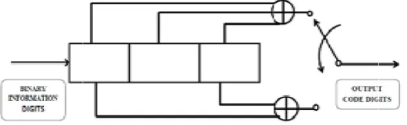
is shown in Figure 3. The rectangular box denotes one element of a
contents of the shift registers are shifted from left to right. XOR operation symbolizes circle with a plus sign inside it. A stream of binary digits is multiplexed as Outputs. One binary digit gives two code digits as output in
= k / n The constraint length K which denotes shifts over message bit for encoder output.
2. Block diagram view of shift registers in convolutional coding
Fig. 3. Block Diagram K=3
are used in a satellite communications. Convolutional codes are effective because they are intuitive. In resulting to increases the transmission redundancy, Convolutional n Sun and Zhizhong Ding, 2012). The set of all possible transmitted messages are decoded and recovered using Viterbi decoder. Code’s constraint length is known as size of int length. A convolutional code is employed in ).The trade-off is a higher amount is shown in Figure 1.
……….. (1)
……… (2)
……… (3)
………. (4)
……… (5)
convolutional coding which represent above equation is shown in Figure 2.
is shown in Figure 3. The rectangular box denotes one element of a serial shift register contents of the shift registers are shifted from left to right. XOR operation symbolizes circle with a plus sign inside it. A serial One binary digit gives two code digits as output in encoder. Hence code rate = ½
Operation of Convolutional Encoder Constraint Length K =7
Seven bit serial shift registers is used for k = 7. The contents of the shift registers are shifted from left to right. Output code word is obtained by performing modulo 2 additions as shown in Figure 4.
R
ESULTSAND
DISCUSSION
CONSTRAINT LENGTH K=3
As per Figure 3 the MATLAB program and VHDL source code have been written and executed for convolutional encoder with
half of input data stream & constraint length k=3.
The code word is obtained based on shifting and XOR operations with given generator polynomial and the input data as follows. Consider the generator polynomials as G1=111=7, G2=101=5 and binary input as 11.
Step 1: Initially if M0=0, M1=0 and M2=0 then the coded bits are First coded bit= 0 XOR 0 XOR 0 = 0
Second coded bit = 0 XOR 0 = 0
As a result, if input=0 then output=00, it displays output for rate ½ convolutional encoder.
Step 2: If input =1, shift registers perform shifting and get M0=1 M1=0 and M2=0 First coded bit= 1 XOR 0 XOR 0 = 1
Second coded bit = 1 XOR 0 = 1 Thus, if input=1 then output=11
Step 3: Similarly if input=1, then M0=1 M1=1 and M2=0 First coded bit= 1 XOR 1 XOR 0 = 0
Second coded bit = 1 XOR 0 = 1 Thus, if input= 1 then output=01.
MATLAB Output
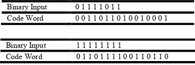
MATLAB program is mainly written to check the functionality of convolutional encoder. An eight bit binary input code is taken as input for K = 3 and the loop is created to process input bit one by one. The main operation shifting and XOR operation are processed and 16 bit output code is generated with help of concatenation of two output switch. The output code word has been obtained from the MATLAB program for the given 8 bit binary input data which is tabulated in 1.
Fig. 4. Block Diagram K=7
Table 1. MATLAB Input and Output
Binary Input 0 1 1 1 1 0 1 1
Code Word 0 0 1 1 0 1 1 0 1 0 0 1 0 0 0 1
Binary Input 1 1 1 1 1 1 1 1
Code Word 0 1 1 0 1 1 1 1 0 0 1 1 0 1 1 0
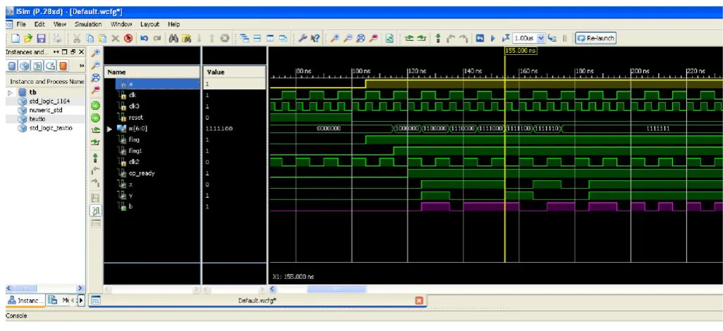
VHDL Output
The output waveform of VHDL source code is shown in Figure 5. The convolutional encoder is saved in text file.
X1=M (0) XOR M (1) XOR M (2) ………..……… (6)
X2=M (0) XOR M (2) ………. (7)
Equation 6 and 7 is represents the operation carried out for constraint length k=3.
CONSTRAINT LENGTH K=7
Accordingto figure 4 the MATLAB program and VHDL source code have been written and executed for convolutional encoder
with half the rate of input data stream & constraint length k=7. There are seven shift-registers where the first register takes the incoming data bit and the rest of register is act as a memory of the encoder for XOR operation.
MATLAB Output
A MATLAB program is written for K= 7 which has seven bit memory registers. The operation is similar to the pervious section up to loop and shifting. XOR operation is not possible for 7 bits at a time, so that operation is dividing in various sub operation and output is placed in respectively and 16 bit output is taken. The MATLAB program output is tabulated as shown in Table 3 where the input is the 8 bit binary data and the output is the 16 bit code word.
Table 2. VHDL waveform output signals and Description
Sl.No SIGNALS DESCRIPTION
1 a Binary input digits
2 Clk Clock signal for all operation
3 Clk2 Used to store X and Y output
4 Clk3 Used to load the output to notepad
5 reset Used to refresh operation
6 flag Used to indicate starting of shift register operation
7 flag1 Used to indicate starting of XOR logic operation
8 Op_ready Used to indicate starting of loading output to notepad
Fig 5. Waveform Output for K=3
Table 3. MATLAB Input and Output (K=7)
Binary Input 1 1 1 1 1 1 1 1
VHDL Output
VHDL source code is written according to figure 4 with many numbers of signals used for specify the operation as shown in Table 2.
X1=M (6) XOR M (5) XOR M (4) XOR M (3) XOR M (0)………... (8) X2=M (6) XOR M (4) XOR M (3) XOR M (1) XOR M (0)……… (9)
Equation 8 and 9 is represents the operation carried out for constraint length k=7.The output for the VHDL source code in waveform format is shown in Figure 6.
Conclusion
The convolution encoder with half the rate of input data stream and constraint length k=3 & k=7 have been designed and corresponding source codes have been generated. The source codes for the two encoders have been programmed using MATLAB and VHDL. The outputs of MATLAB source code has been used for comparison analysis of VHDL source code outputs. MATLAB is mainly used to check the functionality of the encoder. The convolution encoders have been generated using MATLAB and VHDL code and their results are verified.
REFERENCES
Andrew, J., Viterbi and Jim K. Omura, 1979. “Principle of digital communication and coding”, McGraw-Hill, international edition.
Han Vinck, A. J. July 1998. Senior member IEEE, Petr Dolezal and Young Gil Kim, “Convolutional Encoder State Estimation”, IEEE Transactions on Information Theory, Vol. 44, No. 4.
Kavinilavu1, V., Salivahanan, S. and Kanchana Bhaaskaran2, V. S. April 2011. Samiappa Sakthikumaran, B. Brindha and C. Vinoth, “Implementation of convolutional encoder and viterbi decoder using verilog HDL”, IEEE trans. ICECT , vol. 1, pp. 297-300.
Yan Sun, Zhizhong Ding July 2012. "FPGA Design and Implementation of a Convolutional Encoder and a Viterbi Decoder Based on 802.11a for OFDM", Wireless Engineering and Technology, 2012, 3, 125-131, doi:10.4236/wet.2012.33019 Published Online.
Fig 6. Waveform Output for K=7