MODELLING AND ANALYSIS OF A
CAR FOR REDUCING
AERODYNAMIC FORCES
A.Anish1, Suthen.P.G2, Viju.M.K31
Assistant Professor, Department of Mechanical Engineering, Ponjesly college of Engineering Nagercoil, Kanyakumari, India
2
Student, Department of Mechanical Engineering, Ponjesly college of Engineering Nagercoil, Kanyakumari, India
3
student, Department of Mechanical Engineering, Ponjesly college of Engineering Nagercoil, Kanyakumari, India
Abstract
Performance, handling, safety, and comfort of a car are significantly affected by its aerodynamic properties. Getting high power directly from the engine is just not enough to judge the performance of the car. Aerodynamics affects the performance of vehicle due to change in parameters such as lift and drag forces which play a significant role at high speed. With improvement in computer technology, manufacturers are looking toward CFD instead of wind tunnel testing to reduce the testing time and keep the cost of R&D low. In this project by reducing the difference in pressure the drag force will be reduced hence the fuel consumption will be reduced. The car body is often optimized for reducing the drag resistance but in this project some of the additional components are added to reduce the drag and lift. The additional components are diffuser, vortex generator, spoiler, tyre cover and air ducts. Thereby reducing the drag and lift will improve the car handling behavior, acceleration and fuel efficiency. The approach needed to justify the amount of drag and lift that can be reduced by addition of those components as compared to the Maruti Suzuki Swift Dzire car model without those additional components.
Keywords: CFD, Acceleration, fuel efficiency, drag, lift
I. INTRODUCTION
Aerodynamics is the branch of dynamics that deals with the motion of air and other gaseous fluids and with the forces acting on bodies in motion relative to such fluids. For some classes of racing vehicles, it may also be important to produce desirable downwards aerodynamic forces to improve traction and thus cornering abilities.
exhaust system into the rear diffuser, you can also help extract the air from the rear of the car more effectively. In the second modification Rear Spoiler is added. Adding a rear spoiler creates a longer, gentler slope or angle of attack from the roof to the aerodynamic aid. This will help delay flow separation of the fast moving air and increase the flow dynamics of the rear airflow. This decreases drag, increases fuel economy, and also can helps keep the rear window clean when rear wipers are not fitted
II. METHODOLOGY
2.1 Objectives
1) To analyze the effect of diffuser, vortex generator, spoiler, tyre cover and air ducts with diffuser on vehicle in term of velocity and pressure.
2) To estimate percent reduction and compare the drag coefficient and Lift coefficient of vehicle between with and without diffuser, vortex generator, spoiler, tyre cover and air ducts with diffuser.
3) To improve the fuel efficiency, acceleration and handling behaviour of the car.
2.2 Scopes
1) Study on aerodynamics drag reduction by diffuser, vortex generator, spoiler, tyre cover and air ducts with diffuser.
2) Redevelop the existing model of diffuser, vortex generator, spoiler, tyre cover and air ducts with Solid Work 2016.
3) Simulate the model by using Computational Fluid Dynamic (CFD) in Solid Works Flow Simulation 2016.
4) To compare the drag and lift for both with and without diffuser, vortex generator, spoiler, tyre cover and air ducts with diffuser
2.3 Modelling
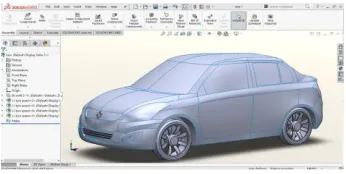
Modelling, in which the geometries of the reference and non-tested store configurations are created. The geometric modelling is performed in the surface modelling software Solid Works 2016. The basic building objects of the sumo models are bodies and wings. Each model may consist of an arbitrary number of such objects. The user also has the option to define parts of objects as inflow and outflow regions. Bodies are defined by specifying points at the body surface at a series of cross-sections. The software connects the cross-sections using interpolation, thereby creating a continuous body surface.
Fig 2.1: Original Car Model of Swift Dzire in Solid Works 2016
Pre-processing
Preprocessing, in which the computational mesh is created and prepared for simulation and input files, which contain relevant information for the simulation, are created.
Computational Domain
The computational domain is designed to lead to a free flow with neglect able blockages, which essentially means a box that consists of an inlet, an outlet, two sides, a roof and a ground surface. The total dimensions are presented in Table 2.1.
Size of Computational Domain
X min -4.332 m
X max 7.506 m
Y min -0.809 m
Y max 3.609 m
Z min -2.048 m
Z max 2.145 m
Table 2.1: Size of Computational Domain
Fig 2.2: Computational Domain
Mesh Generation
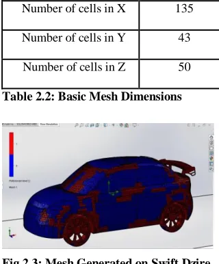
The surface mesh for the finished, integrated model is obtained using the built-in meshing Features of Solid Works 2016. The unstructured mesh is generated automatically, based on the geometries of the supplied model and a number of user-defined parameters. Of these parameters, which can be set separately for each surface – body, inflow/outflow region or control surface – in the model, the most prominent are the definitions of maximum and minimum element edge length. These allow the user to choose which surfaces should be resolved in greater detail and which should be resolved in less detail.
Basic Mesh Dimensions
Number of cells in X 135
Number of cells in Y 43
Number of cells in Z 50
Table 2.2: Basic Mesh Dimensions
Fig 2.3: Mesh Generated on Swift Dzire
For each surface, the software provides a default setting for each parameter, based on geometric properties such as curvature. The mesh is automatically adapted near the intersections of different surfaces, in order to obtain a complete, closed mesh.
Boundary Condition
In this section a short description of boundary conditions is presented in order to give an overview of the driving condition during the simulation enclosure inlet plane was named “velocity-inlet”. The road and the vehicle body were both made walls. The surrounding enclosure surfaces, being imaginary surfaces, were all named symmetry planes having a ‟no slip‟ condition. The outlet was named a “pressure-outlet” with its pressure set constant and equal to atmospheric pressure.
Simulation
The model was further imported to simulation software Solid Works Flow Simulation 2016
which specializes in solving CFD problems. In a view to simulate real life conditions we decided to simulate the forces acting on the car when it moves at a speed of 40 m/s (approx. 144 km/hr.) the choice for speed is for the purpose of magnifying the effects of drag force so that it is easily measurable. No slip conditions were given to both road and the body of the car. We decided to go ahead with a comparatively coarse mesh considering our hardware and time limitations. On first solving with steady state conditions we encountered ripples in residual output and in both Cd and Cl values and then we changed to transient solver. We kept a time step value of 0.001 which was enough to ensure convergence within 120-135 iterations per time step. This parameter is very important in order to ensure fidelity of the solution.
Post Processing
The velocity, pressure contours of modified Swift Dzire is analyzed in this process. When the simulations have reached convergent or at least satisfying non-divergent, solutions, the post-processing step follows. Initially, the solutions must be inspected to determine whether the results can be assumed to be reliable. This is particularly important if the convergence criteria were not met. The first source for information about convergence rate etc. is the residual output file, to which the Edge solver regularly writes residual data during the solution process. This allows the user to assess global convergence by monitoring the magnitude of the residuals and the integrated values of forces and moments as functions of iteration number for the entire mesh.
2.4.CASE DESCRIPTION
Diffuser
A diffuser, in an automotive context, is a shaped section of the car under body which improves the car's aerodynamic properties by enhancing the transition between the high-velocity airflow underneath the car and the much slower free stream airflow of the ambient atmosphere.
Fig 2.4: Diffuser normal Function
It works by accelerating the velocity of the airflow underneath the car. The pressure under the car is affected by the diffuser so that it can expand back to ambient in the diffuser, as the car moves through the air. It uses Bernoulli's principle, such that the pressure decreases while the velocity increases. Since the pressure below the car is lower than on the side and above the car, downforce is produced if implemented correctly. The diffuser "drives" the underbody, which produces the downforce. Front diffusers also exist; however, they generate downforce purely from momentum exchange with the air, as there is nothing ahead of them to drive. A poorly designed front diffuser can create a low pressure region toward the front of the car which slows the air behind it down and reduces the effectiveness of the rest of the underbody. Front diffusers usually route air away from the car so
that it doesn't affect the rest of the underbody. The air can be vented through a channel.
Fig 2.5: Modified Swift Dzire with Rear Diffuser
The reduction in pressure at the throat area as the velocity increases and the subsequent reduction in pressure for the under floor as the diffuser sucks the car to the ground. The velocity of the air decrease as it moves along the diffuser, which in turn creates the increase in pressure. This fast-moving air helps evacuate the diffuser more quickly, which helps drop the pressure at the underbody. However, this makes the diffuser rather sensitive to engine speed.
Vortex Generator
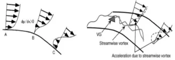
A vortex generator (VG) is an aerodynamic device, consisting of a small vane usually attached to a lifting surface (or airfoil, such as an aircraft wing) or a rotor blade of a wind turbine. VGs may also be attached to some part of an aerodynamic vehicle such as an aircraft fuselage or a car. The purpose of adding VGs is to supply the momentum from higher region where has large momentum to
lower region where has small momentum by stream wise vortices generated from VGs located just before the separation point.
Fig 2.6: Schematics of velocity
Vortex generators are most often used to delay flow separation. To accomplish this, they are often placed on the external surfaces of vehicles. Vortex generators are positioned obliquely so that they have an angle of attack with respect to the local airflow in order to create a tip vortex which draws energetic, rapidly moving outside air into the slow-moving boundary layer in contact with the surface. A turbulent boundary layer is less likely to separate than a laminar one, and is therefore desirable to ensure effectiveness of trailing-edge control surfaces. Vortex generators are used to trigger this transition.
Fig 2.7: Modified Swift Dzire with Vortex Generator
level, which suggests that there must be an optimum size for VGs.
Spoiler
A spoiler is an automotive aerodynamic device whose intended design function is to 'spoil' unfavourable air movement across a body of a vehicle in motion, usually described as turbulence or drag. Spoilers on the front of a vehicle are often called air dams. Spoilers are often fitted to race and high-performance sports cars, although they have become common on passenger vehicles as well. Some spoilers are added to cars primarily for styling purposes and have either little aerodynamic benefit or even make the aerodynamics worse. While a mass is travelling at increasing speeds, the air of the environment affects its movement. Spoilers in racing are used in combination with other features on the body or chassis of race cars to change the handling characteristics that are affected by the air of the environment.
Fig 2.8: Modified Swift Dzire with Spoiler
The goal of many spoilers used in passenger vehicles is to reduce drag and increase fuel efficiency. Passenger vehicles can be equipped with front and rear spoilers. Front spoilers, found beneath the bumper, are mainly used to decrease the amount of air going underneath the vehicle to reduce the drag coefficient and lift. Sports cars are most commonly seen with front and rear spoilers. Even though these vehicles typically have a more rigid chassis and a stiffer suspension to aid in high speed, a spoiler can still be beneficial. This is because many vehicles have a fairly steep downward angle going from the rear edge of the roof down to the trunk or tail of the car which may cause air flow separation. The flow of air becomes turbulent and a low-pressure zone is created, increasing drag and instability (see Bernoulli effect). Adding a rear spoiler could be considered to make the air "see" a longer, gentler slope from the roof to the spoiler, which helps to delay flow separation and the higher pressure in front of the spoiler can help reduce the lift on the car by creating downforce. This may reduce drag in certain instances and will generally increase high speed stability due to the reduced rear lift.
Tyre Cover
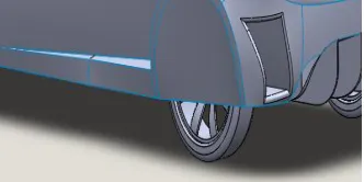
The flow that originates from the rear wheel has a major impact on the air flow in the diffuser and by restricting this flow some interesting results can be obtained. This case simply be performed by covering the rear tyre and restricting the air flow on the rear tyre zone. It should be pointed out that this has the major influence on the cooling of the brake and therefore air ducts are provided on the both side of the rear end.
Fig 2.9: Modified Swift Dzire with Tyre Cover
Air Ducts
While you control your vehicle, the Air Ducts controls the airstream. This is because it reduces the air resistance of the body in an astonishingly simple, yet highly effective way. Its narrowing channels speed up the airstream and guide it past the wheels. This reduces the air turbulence in the wheel housings and decreases the drag due to the body as well as the fuel consumption. You’re moving faster and faster. But you still cannot detect any air resistance. This is because the air ducts channel the air on the rear wheels. It reduces turbulence on the wheel housings and breaks down the air swirls. Fuel consumption is decreased.Air ducts are primarily seen on race cars for two reasons, because brake and engine cooling. They are found behind front or rear wheel. They were first adapted for racing coupes
Fig 2.10: Modified Swift Dzire with Air Duct
side of the car. This reduction of air stagnation inside the tire bay also helps pull more fresh air through the cooling system. Air ducts can come separate or with customized body kit assemblies. Air ducts will improve your car's speed and make fuel consumption less. The holes on the air ducts are usually large enough to prevent obstruction from objects coming from the vehicle's travel environment.
2.5. BOUNDARY CONDITIONS FOR THE CFD ANALYSIS
To simulate a passenger car moving on an actual road. The dimension of the computational domain is chosen such that the aerodynamic force is not affected by the domain size. Although numerous studies have investigated aerodynamic drag reduction on the configuration of a car, most did not consider the moving ground and rotating wheel effects, which have a critical effect on the automobile’s rear flow characteristics. Given the moving ground and rotating wheel conditions, it is known that a Swift Dzire shows quite different aerodynamic characteristics from that on stationary ground and under a stationary wheel condition. Therefore, every numerical simulation in this study was performed under the moving ground and rotating wheel conditions. The angular velocities of the rotating wheels and the speed of the moving ground were set according to the driving speed.
Table 2.3: Boundary Conditions for the CFD analysis
Flow analysis
The model was further imported to simulation software SolidWorks Flow Simulation 2016 which specializes in solving CFD problems. In a view to simulate real life conditions we decided to simulate the forces acting on the car when it moves at a speed of 40 m/s (approx. 144 km/hr.) the choice for speed is for the
purpose of magnifying the effects of drag force so that it is easily measurable. For simulation a control volume was made on similar lines of Ahmed body control volume, in order to make sure that all the relevant characteristics of turbulence in the flow are captured.
#
Fig 2.11: Flow analysis
No slip conditions were given to both road and the body of the car. On the output pressure gradient was given as 0-gauge pressure. We decided to go ahead with a comparatively coarse mesh considering our hardware and time limitations. On first solving with steady state conditions we encountered ripples in residual output and in both Cd and Cl values and then we changed to transient solver. We kept a time step value of 0.001 which was enough to ensure convergence within 10-15 iterations per time step. This parameter is very important in order to ensure fidelity of the solution.
III. RESULT AND DISCUSSION
To be able to analyze a different configuration a detailed analysis of unmodified reference is done in order to get an overview of the flow behavior and establish a starting point for improvements. Pressure Contour, Velocity Contour, analyzed goals and Global max-min tables are presented for Swift Dzire with all modifications and without modifications to show the clear variations.
3.1.Actual Reference of Maruti Suzuki Swift Dzire without modifications
Fig 3.1: Swift Dzire without modifications
Pressure 101325 Pa
Temperature 293.2 K
Defined By 3D Vector
X-Direction 40 m/s
Y-Direction 0 m/s
Z-Direction 0 m/s
Intensity 0.1 %
Length 0.0150529346 m
Coordinate System
Global Coordinate System
Flow Type Inlet mass flow
Flow Rate
0.0001 kg/s (Uniform mass flow
rate)
Maruti Suzuki Swift Dzire without Modification
Fig 3.1.a: Pressure Contour without modifications
Fig 3.1.b: Velocity Contour without modifications
Analyzed goals
Name Value
Cd 0.3089
Cl 0.3407
Drag force 646.30 N
Lift force 712.42 N
Table 3.1.a: Analyzed goals of without modifications
Global Max-Min table
Table 3.1.b: Global Max-Min
Name Minimum Maximum
Density (Fluid)
[kg/m^3] 1.19 1.21
Pressure [Pa] 100073.94 102341.46
Temperature [K] 292.68 294.03
Temperature
(Fluid) [K] 292.68 294.03
Velocity [m/s] 0 50.907
Velocity (X) [m/s] -15.133 49.312 Velocity (Y) [m/s] -35.332 32.846 Velocity (Z) [m/s] -34.231 33.978
Mach Number [ ] 0 0.15
Velocity RRF [m/s] 0 50.907
Velocity RRF (X)
[m/s] -15.133 49.312
Velocity RRF (Y)
[m/s] -35.332 32.846
Velocity RRF (Z)
[m/s] -34.231 33.978
Vorticity [1/s] 9.28e-003 1509.42 Relative Pressure
[Pa] -1251.06 1016.46
Shear Stress [Pa 0 22.45
Bottleneck Number [ ]
4.2243792e-014 1.0000000
Heat Transfer Coefficient
[W/m^2/K] 0 0
ShortCut Number [ ]
1.7124823e-012 1.0000000
Surface Heat Flux (Convective)
[W/m^2] 0 0
Turbulence
Intensity [%] 0.09 1000.00
Turbulence Length
[m] 4.398e-004 0.083
Turbulent
Dissipation [W/kg] 9.75e-004 15105.71 Turbulent Energy
[J/kg] 0.002 84.283
Turbulent Time [s] 0.002 2.136
Turbulent Viscosity
Data Analysis with Diffuser
Maruti Suzuki Swift Dzire with Diffuser
Fig 3.2.a: Pressure Contour with Diffuser
Fig 3.2.b: Velocity Contour with Diffuser
Analyzed goals
Table 3.2.a: Analyzed goals of Diffuser
Global Max-Min table
Table 3.2.b: Global Max-Min
Name Minimum Maximum
Density (Fluid)
[kg/m^3] 1.19 1.21
Pressure [Pa] 100053.14 102340.79
Temperature [K] 292.69 294.09
Temperature (Fluid)
[K] 292.69 294.09
Velocity [m/s] 0 50.574
Velocity (X) [m/s] -14.921 49.191
Velocity (Y) [m/s] -35.135 34.392
Velocity (Z) [m/s] -34.078 33.778
Mach Number [ ] 0 0.15
Velocity RRF [m/s] 0 50.574
Velocity RRF (X)
[m/s] -14.921 49.191
Velocity RRF (Y)
[m/s] -35.135 34.392
Velocity RRF (Z)
[m/s] -34.078 33.778
Vorticity [1/s] 0.01 1952.87
Relative Pressure [Pa] -1271.86 1015.79
Shear Stress [Pa 0 22.39
Bottleneck Number [ ]
4.2243792e-014 1.0000000
Heat Transfer
Coefficient [W/m^2/K] 0 0
ShortCut Number [ ]
1.3405936e-013 1.0000000
Surface Heat Flux
(Convective) [W/m^2] 0 0
Turbulence Intensity
[%] 0.09 1000.00
Turbulence Length [m] 3.719e-004 0.066 Turbulent Dissipation
[W/kg] 9.73e-004 16170.42
Turbulent Energy
[J/kg] 0.002 108.772
Turbulent Time [s] 0.002 2.137
Turbulent Viscosity
[Pa*s] 1.9000e-005 0.1593
Name Value
Cd 0.2633
Cl 0.2783
Drag force 550.88 N
Data Analysis with Vortex Generator
Maruti Suzuki Swift Dzire with Vortex Generator
Fig 3.3.a: Pressure Contour with Vortex Generator
Fig 3.3.b: Velocity Contour with Vortex Generator
Analyzed goals
Table 3.3.a: Analyzed goals of Vortex Generator
Global Max-Min table
Name Minimum Maximum
Density (Fluid)
[kg/m^3] 1.19 1.21
Pressure [Pa] 100086.50 102341.50
Temperature [K] 292.68 294.03
Temperature (Fluid)
[K] 292.68 294.03
Velocity [m/s] 0 50.896
Velocity (X) [m/s] -17.755 49.298
Velocity (Y) [m/s] -35.326 32.923
Velocity (Z) [m/s] -34.244 33.976
Mach Number [ ] 0 0.15
Velocity RRF [m/s] 0 50.896
Velocity RRF (X)
[m/s] -17.755 49.298
Velocity RRF (Y)
[m/s] -35.326 32.923
Velocity RRF (Z)
[m/s] -34.244 33.976
Vorticity [1/s] 0.01 2170.35
Relative Pressure [Pa] -1238.50 1016.50
Shear Stress [Pa 0 22.44
Bottleneck Number [ ]
9.9814325e-014 1.0000000
Heat Transfer Coefficient
[W/m^2/K] 0 0
ShortCut Number [ ]
1.3405936e-013 1.0000000
Surface Heat Flux
(Convective) [W/m^2] 0 0
Turbulence Intensity
[%] 0.09 1000.00
Turbulence Length
[m] 4.304e-004 0.084
Turbulent Dissipation
[W/kg] 9.75e-004 15376.18
Turbulent Energy
[J/kg] 0.002 91.023
Turbulent Time [s] 0.002 2.137
Turbulent Viscosity
[Pa*s] 1.0539e-005 0.2837
Table 3.3.b: Global Max-Min
Name Value
Cd 0.3078
Cl 0.3358
Drag force 644.01 N
Data Analysis with Spoiler
Maruti Suzuki Swift Dzire with Spoiler
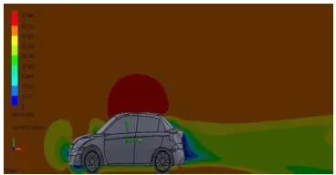
Fig 3.4.a: Pressure Contour with Spoiler
Fig 3.4.b: Velocity Contour with spoiler
Analyzed goals
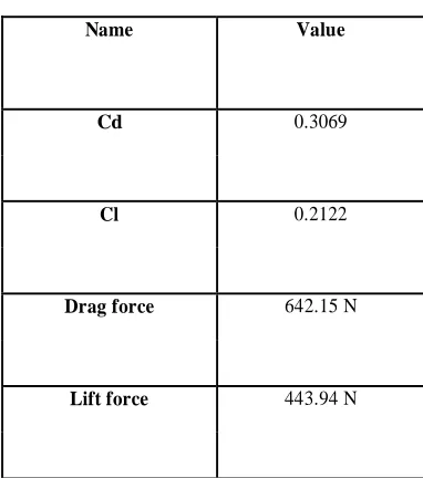
Table 3.4.a: Analyzed goals of Spoiler
Global Max-Min table
Table 3.4.b: Global Max-Min Name Value
Cd 0.3069
Cl 0.2122
Drag force 642.15 N
Lift force 443.94 N
Name Minimum Maximum
Density (Fluid)
[kg/m^3] 1.19 1.21
Pressure [Pa] 100213.45 102341.41
Temperature [K] 292.69 294.03
Temperature (Fluid)
[K] 292.69 294.03
Velocity [m/s] 0 50.765
Velocity (X) [m/s] -17.805 49.122
Velocity (Y) [m/s] -35.313 32.734
Velocity (Z) [m/s] -34.305 34.013
Mach Number [ ] 0 0.15
Velocity RRF [m/s] 0 50.765
Velocity RRF (X)
[m/s] -17.805 49.122
Velocity RRF (Y)
[m/s] -35.313 32.734
Velocity RRF (Z)
[m/s] -34.305 34.013
Vorticity [1/s] 0.01 2254.81
Relative Pressure [Pa] -1111.55 1016.41
Shear Stress [Pa 0 23.56
Bottleneck Number [ ]
2.8178274e-012 1.0000000
Heat Transfer Coefficient
[W/m^2/K] 0 0
ShortCut Number [ ]
1.3405936e-013 1.0000000
Surface Heat Flux
(Convective) [W/m^2] 0 0
Turbulence Intensity
[%] 0.09 1000.00
Turbulence Length
[m] 4.289e-004 0.088
Turbulent Dissipation
[W/kg] 9.75e-004 15341.81
Turbulent Energy
[J/kg] 0.002 92.917
Turbulent Time [s] 0.002 2.136
Turbulent Viscosity
Data Analysis with Tyre Cover
Maruti Suzuki Swift Dzire With Tyre Cover
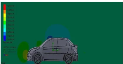
Fig 3.5.a: Pressure Contour with Tyre Cover
Fig 3.5.b: Velocity Contour with Tyre Cover
Analyzed goals
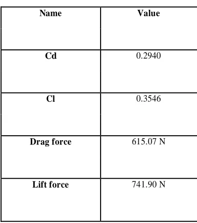
Table 3.5.a: Analyzed goals of Tyre Cover
Global Max-Min table
Table 3.5.b: Global Max-Min Name Value
Cd 0.2940
Cl 0.3546
Drag force 615.07 N
Lift force 741.90 N
Name Minimum Maximum
Density (Fluid)
[kg/m^3] 1.19 1.21
Pressure [Pa] 100042.77 102341.56
Temperature [K] 292.68 294.09
Temperature (Fluid)
[K] 292.68 294.09
Velocity [m/s] 0 50.958
Velocity (X) [m/s] -14.487 49.358
Velocity (Y) [m/s] -35.304 31.516
Velocity (Z) [m/s] -34.240 33.981
Mach Number [ ] 0 0.15
Velocity RRF [m/s] 0 50.958
Velocity RRF (X)
[m/s] -14.487 49.358
Velocity RRF (Y)
[m/s] -35.304 31.516
Velocity RRF (Z)
[m/s] -34.240 33.981
Vorticity [1/s] 0.01 1126.54
Relative Pressure [Pa] -1282.23 1016.56
Shear Stress [Pa 0 22.18
Bottleneck Number [ ]
1.0534235e-012 1.0000000
Heat Transfer Coefficient
[W/m^2/K] 0 0
ShortCut Number [ ]
1.2816187e-013 1.0000000
Surface Heat Flux
(Convective) [W/m^2] 0 0
Turbulence Intensity
[%] 0.09 1000.00
Turbulence Length
[m] 3.313e-004 0.069
Turbulent Dissipation
[W/kg] 9.75e-004 14981.51
Turbulent Energy
[J/kg] 0.002 93.608
Turbulent Time [s] 0.002 2.136
Turbulent Viscosity
Data Analysis with Air Ducts including diffuser Maruti Suzuki Swift Dzire with Air Ducts including diffuser
Fig 3.6.a: Pressure Contour with Air Ducts including diffuser
Fig 3.6.b: Velocity Contour with Air Ducts including diffuser
Analyzed goals
Name Value
Cd 0.2688
Cl 0.2969
Drag force 562.38 N
Lift force 621.30 N
Table 3.6.a: Analyzed goals of Air Ducts with diffuser
Global Max-Min table
Table 3.6.b: Global Max-Min
Name Minimum Maximum
Density (Fluid)
[kg/m^3] 1.19 1.23
Pressure [Pa] 100029.93 103884.82
Temperature [K] 292.70 294.06
Temperature (Fluid)
[K] 292.70 294.06
Velocity [m/s] 0 50.483
Velocity (X) [m/s] -14.777 49.067
Velocity (Y) [m/s] -35.159 26.933 Velocity (Z) [m/s] -34.218 36.862
Mach Number [ ] 0 0.15
Velocity RRF [m/s] 0 50.958
Velocity RRF (X)
[m/s] -14.777 49.067
Velocity RRF (Y)
[m/s] -35.159 26.933
Velocity RRF (Z)
[m/s] -34.218 36.862
Vorticity [1/s] 0.01 1219.35
Relative Pressure [Pa] -1295.07 2559.82
Shear Stress [Pa 0 22.16
Bottleneck Number [ ]
9.2483583e
-013 1.0000000
Heat Transfer Coefficient
[W/m^2/K] 0 0
ShortCut Number [ ]
5.0407698e
-013 1.0000000
Surface Heat Flux
(Convective) [W/m^2] 0 0
Turbulence Intensity
[%] 0.09 1000.00
Turbulence Length
[m] 2.783e-004 0.064
Turbulent Dissipation
[W/kg] 9.75e-004 14981.51
Turbulent Energy
[J/kg] 0.002 93.608
Turbulent Time [s] 0.002 2.137
Turbulent Viscosity [Pa*s]
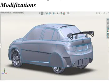
Maruti Suzuki Swift Dzire with Full Modifications
Fig 3.7: Swift Dzire with full modifications
Maruti Suzuki Swift Dzire with full modification
Fig 3.7.a: Pressure Contour with full modifications
Fig 3.7.b: Velocity Contour with full modification
Analyzed goals
Table 3.7.a: Analyzed goals of Air Ducts with full modification
Global Max-Min table
Table 3.7.b: Global Max-Min
Name Minimum Maximum
Density (Fluid)
[kg/m^3] 1.19 1.23
Pressure [Pa] 100212.14 103594.73
Temperature [K] 292.70 294.07
Temperature (Fluid)
[K] 292.70 294.07
Velocity [m/s] 0 50.392
Velocity (X) [m/s] -14.737 48.908
Velocity (Y) [m/s] -35.159 26.933
Velocity (Z) [m/s] -34.218 36.862
Mach Number [ ] 0 0.15
Velocity RRF [m/s] 0 50.958
Velocity RRF (X)
[m/s] -14.777 49.067
Velocity RRF (Y)
[m/s] -35.160 25.305
Velocity RRF (Z)
[m/s] -34.308 34.113
Vorticity [1/s] 7.15e-003 1498.63
Relative Pressure
[Pa] -1112.86 2269.73
Shear Stress [Pa 0 22.15
Bottleneck Number [ ]
8.1372090e-013 1.0000000
Heat Transfer Coefficient
[W/m^2/K] 0 0
ShortCut Number [ ]
1.7944486e-013 1.0000000
Surface Heat Flux (Convective)
[W/m^2] 0 0
Turbulence Intensity
[%] 0.09 1000.00
Turbulence Length
[m] 2.933e-004 0.066
Turbulent
Dissipation [W/kg] 9.77e-004 16024.03 Turbulent Energy
[J/kg] 0.002 280.688
Turbulent Time [s] 0.002 2.135
Turbulent Viscosity
[Pa*s] 2.0576e-005 0.1313
Name Value
Cd 0.2732
Cl 0.1800
Drag force 571.60 N
Maruti Suzuki Swift Dzire with excluded Air Ducts from the Full Modifications
Fig 3.8: Swift Dzire with excluded Air Ducts from the full modifications
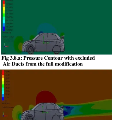
Maruti Suzuki Swift Dzire with excluded air ducts from full Modifications
Fig 3.8.a: Pressure Contour with excluded Air Ducts from the full modification
Fig 3.8.b: Velocity Contour with excluded Air Ducts from the full modification
Analyzed goals
Name Value
Cd 0.2680
Cl 0.1608
Drag force 560.74 N
Lift force 336.57 N
Table 3.8.a: Analyzed goals with excluded Air Ducts from the full modification
Global Max-Min table
Table 3.8.b: Global Max-Min
Name Minimum Maximum
Density (Fluid)
[kg/m^3] 1.19 1.21
Pressure [Pa] 100203.42 102340.44
Temperature [K] 292.69 294.10
Temperature
(Fluid) [K] 292.69 294.10
Velocity [m/s] 0 50.527
Velocity (X)
[m/s] -14.948 49.026
Velocity (Y)
[m/s] -35.148 33.059
Velocity (Z)
[m/s] -34.166 33.838
Mach Number [
] 0 0.15
Velocity RRF
[m/s] 0 50.527
Velocity RRF
(X) [m/s] -14.948 49.026
Velocity RRF
(Y) [m/s] -35.148 33.059
Velocity RRF
(Z) [m/s] -34.166 33.838
Vorticity [1/s] 0.01 1330.76
Relative
Pressure [Pa] -1121.58 1015.44
Shear Stress [Pa 0 22.15
Bottleneck Number [ ]
3.5774168e-013 1.0000000
Heat Transfer Coefficient
[W/m^2/K] 0 0
ShortCut Number [ ]
1.4557382e-012 1.0000000
Surface Heat Flux (Convective)
[W/m^2] 0 0
Turbulence
Intensity [%] 0.09 1000.00
Turbulence
Length [m] 2.740e-004 0.059
Turbulent Dissipation
[W/kg] 9.79e-004 16136.92
Turbulent
Energy [J/kg] 0.002 81.556
Turbulent Time
[s] 0.002 2.134
Turbulent
Table 3.9: Comparison of Analyzed goals with and without modifications
The above Table 3.9 clearly shows the corresponding changes in values of Cd, Cl, Drag and Lift forces with individual modifications, without any modification and with full modification and with all modification excluding air ducts. From the Table 3.9 of comparison results shows the Cd and Cl values changes for the corresponding modifications at a speed of 40 m/s (approx.144km/hr.).Normally Swift Dzire has 0.3089 of Cd and 0.3407 of Cl at a speed of 40 m/s.By adding Diffuser alone, the Cd value is reduced to 15% and the Cl value reduced to 18%.By adding Vortex Generator alone, the Cd value is reduced to 0.35% and the Cl value reduced to 1.44%.By adding Spoiler alone, the Cd value is reduced to 0.65% and the Cl value reduced to 37.7%.By adding Tyre Cover alone, the Cd value is reduced to 4.82% and the Cl value increased to 4.08%.By adding Air Ducts with diffuser, the Cd value is reduced to 13% and the Cl value reduced to 12.8%.Therefore, we have got two good alternative results to choose the best drag and lift reduction techniques.
OPTION A: By adding all the modifications,(Diffuser,Vortex Generator, Spoiler, Tyre Cover andAir Ducts with diffuser)The Cd value is reduced to 11.5% and the Cl value is reduced to 47.2%.OPTION B: By excluding Air Ducts from the above all modifications,(Diffuser,Vortex Generator, Spoiler, and Tyre Cover) The Cd value is reduced to 13.24% and the Cl value is reduced to 52.8%
Chart Plotted for the Comparison of Analyzed goals with and without modifications
Fig 3.9: Comparison of Analyzed goals with and without modification
Name Without
Modifications
With Individual Modifications With Full
Modifications
With All Modifications Excluding Air
Ducts Diffuser Vortex
Generator
Spoiler Tyre Cover
Air Ducts with diffuser
Cd 0.3089 0.2633 0.3078 0.3069 0.2940 0.2688 0.2732 0.2680
Cl 0.3407 0.2783 0.3358 0.2122 0.3546 0.2969 0.1800 0.1608
Drag force
646.30 N 550.88 N 644.01 N 642.15 N 615.07 N 562.38 N 571.60 N 560.74 N
Lift force
Indications on Chart
____ = Drag Coefficient (Cd)
____ = Lift Coefficient (Cl)
____ = Drag Force in N (FD)
____ = Lift Force in N (FL)
The above Fig 3.9 clearly shows the corresponding variations in the values of Cd, Cl, Drag and Lift forces with full modification and without any modification at a speed of 40 m/s.
IV. CONCLUSION
CFD analysis was successfully carried out on the production vehicle. Once the validity of the simulation was achieved, the next step was to make modifications in the geometry of the original model which could positively affect performance characteristics (lift and drag). The results obtained showed that by modifying the Swift Dzire by adding diffuser, Vortex Generators, Spoilers, and Tyre Cover. The Cd value is reduced from 0.3089 to 0.2680 (13.24%) and the Cl value is reduced from 0.3407 to 0.1608 (52.8%) at a speed of 40m/s. Though this number may appear to be substantially low, this reduction in drag and lift coefficient are considerable from aerodynamic point of view as it reduce the power consumption, improve the acceleration and handling behaviour.
From the above result, we prefer OPTION B which gives the best drag and lift reduction result from the two alternatives. We have chosen the best techniques based on the decreased drag and lift values obtained. Therefore, by comparing all the modifications techniques, we have obtained the best result when excluding Air Ducts from the all modifications.
REFERENCE
1. J. D. Anderson, Fundamentals of Aerodynamics (Boston: McGraw-Hill, 2001)
2. Introduction to Computational Fluid Dynamics ( Dmitri Kuzmin)http://www.mathematik.unidortmund.de/kuzmin/ cfdintro/cfd.html
3. Wolf-Heinrich Hucho, Aerodynamics of Road Vehicles, 4th Revised Edition, Society of Automotive Engineers, U.S., 1998, ISBN: 978-0768000290
4. Aerodynamic Analysis of a Car for Reducing Drag Force (Gavin Dias, Nisha R. Tiwari, Joju John Varghese, Graham Koyeerath)
5. Aerodynamic Analysis of a Car Model using Fluent- Ansys (Nov 2014)
6. Design and Analysis the Effect of Rear spoiler and Rear diffuser on Aerodynamic Forces using CFD (Apr 2016) 7. CFD-based Optimization for Automotive Aerodynamics
(Laurent Dumas)
8. An aerodynamic study on mpv spoiler (Raguvaran A/L Jayahkudy)
9. Hucho, W. H., Aerodynamics of Road Vehicles, Fourth Edition, SAE International 1998
10. Cfd report 3d aerodynamic analysis of “AEROCAR” hatchback concept at 80kmph