GSJ: Volume 6, Issue 11, November 2018, Online: ISSN 2320-9186
www.globalscientificjournal.com
D
ESIGN AND IMPLEMENTATION OF AN ABANDONED OBJECT
USING DETECTION METHOD
Y.A Samaila
1, M.B Lawan
1, Ibrahim Tijjani
1, M.A Sarki
1, M.M Gujja
21
Department of Electrical and Electronics Engineering University of Maiduguri, Nigeria
2
Department of Electrical Engineering, Ramat Polytechnic Maiduguri, Nigeria
KeyWords
Abandoned object, Database, Background, Frame Difference, Foreground, Centroid Difference, Stationary
ABSTRACT
1. INTRODUCTION
A digital image can be considered as a discrete representation of data possessing both spatial (layout) and intensity (colour) information. The word pixel is an abbreviation of ‘picture element’. Indexed as an (x; y)or column-row(c; r)location from the origin of the image, it represents the smallest, constituent element in a digital image and contains a numerical value which is the basic unit of information within the image at a given spatial resolution and quantization level. Commonly, pixels contain the colour or intensity response of the image as a small point sample of coloured light from the scene. However, not all images necessarily contain strictly visual information. An image is simply a 2-D signal digitized as a grid of pixels, the values of which may relate to other properties other than colour or light intensity. The information content of pixels can vary considerably depending on the type of image we are processing. A blob is a Collection of Pixels [1].
Digital Image Processing encompasses processes whose inputs and outputs are images and in addition, encompasses processes that extract attributes from images, up to and including the recognition of individual objects. Thus, object detection and recognition stands as an area of research due to its application in surveillance system for abandoned object detection, Removed object detection among others [2].In many cases, terrorists typically put a bomb in personal materials (bag, small box, etc.) and then leave it in a public area. The preventive action is imperative and wide scale deployment of surveillance systems are in demand. In spite of the Sophisticated Surveillance System deployed in many places today, the problem still persist. Such limitations are connected with human involvement in system. Due to human nature, a man cannot continuously monitor a scene round the clock, the manual surveillance fails. Semi-automatic surveillance using close circuit Television (CCTV) also seems ineffective for the fact that man can effectively monitor one scene at a time and with possible distraction. To ease this problem and improve scene monitoring system, a computer based object detection and monitoring system is proposed. From this fact, the surveillance system here is to detect the left/abandoned object and activate the alarms to let the security personnel act on it.
2. RELATED WORK
This section review related work so as to have a clear picture of the research in focus.
2.1 Foreground (FG) Detection
The first stage in the detection of Stationary Foreground Object (SFO) consists of separating the Foreground (FG) from the rest of elements (Background) in the scene using a FG Detection algorithm. The essence of FG Detection is to separate the FG (foreign object to a given scene) from the Background (objects present in the initial scene), for the purpose of detecting the SFO. The FG Detection methods used to detect SFOs vary widely [3].Frame Difference, Gaussian Mixture Model and Optical Flow are some of the renowned method of detecting foreground Object.
The authors in [3] use non-statistical models such as optical flow that, in the simplest cases, the background (BG) models are never updated. The optical flow is based on calculation of optical flow field of image or video frame. Clustering is performed on the basis of the optical flow distribution information obtained from the image .This method allows for obtaining the complete knowledge about the moving target from the scene, which aids in determining it from the background .The disadvantages are large quantity of calculations are required to obtain optical flow information, and cannot be used in real-time without specialized hardware [3].The optical flow method is mainly used for non-stationary cameras and hardly used due to noise problem, complexity, and as well has high computational cost [3].
that are based on using three BG models (Gaussian mixture models) [7,8]. However, it is possible to find some of them using single BG model [9, 10].
2.2 Stationary Foreground Object (SFO) detection
Once the foreground (FG) has been detected through the frame difference method, it is necessary to discriminate between moving objects and stationary foreground objects (SFOs). Tracking of foreground and dual foreground comparison are some of the renowned methods of SFO Detection. Most of the authors in recent times used the tracking algorithm to determine stationary foreground objects. The algorithm allows detecting short term and long term SFOs and additionally deal with occluded SFOs, though detecting of partially stationary foreground objects (PSFO) becomes impossible since they work at object level. Blobs statistics (area, centroid, major axis length, eccentricity) are used by [11,12] to determine if an object is static/stationary or not.
3. MATERIALS AND METHOD
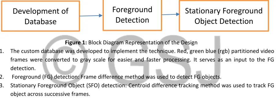
This section gives a detailed description of the materials used and how the objectives of the research were achieved. The block diagram in Figure 1 represents the main stages.
Figure 1: Block Diagram Representation of the Design
1. The custom database was developed to implement the technique. Red, green blue (rgb) partitioned video frames were converted to gray scale for easier and faster processing. It serves as an input to the FG detection.
2. Foreground (FG) detection: Frame difference method was used to detect FG objects.
3. Stationary Foreground Object (SFO) detection: Centroid difference tracking method was used to track FG object across successive frames.
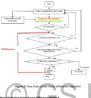
Figure 2 shows the flow chart of the frame difference algorithm.
3.1 Development of Database
The database contains 720p HD video recorded at 20 frames per seconds, captured using a digital cannon Camera. The description of the database is given in Table 1.
Table1: Description of the Abandoned Object Detection Database.
Video Description No. of Frames Object of Interest Size(Pixels)
A Man carrying along a Polythene Bag 297 Polythene Bag 1390
The custom video (data) was used as an input to the Matlab Image Processing Toolbox after pre-processing. Pre-processing involves converting the red, green, blue video frames to gray for easier Pre-processing.
The video featured event that is characterized by object of irregular shape (Polythene Bag). The video was then partitioned to frames (images) for the purpose of processing. Thereafter, the images (rgb) were converted to gray scale for easy processing and manipulation.
Development of
Database
Foreground
Detection
Figure 2: Flow Chart of the Frame Difference Algorithm
3.2 Foreground Object Detection Using Frame Difference Method
The frame difference method identifies the presence of moving object by considering the difference between two consecutive frames. Subtracting the second image from the first image using image subtraction operator in consecutive frame to get the desired output required. It is an efficient method for detecting gray level changes between images by using frame differencing algorithm .The algorithm may be subdivided into three (3) parts. Initial step is the selection of perfect reference or background. Second step is the arithmetic subtraction operation and the third step is the selection of a suitable threshold. Reference image can be selected as a frame which is temporally adjacent image from a dynamic sequence. A threshold is put on this difference image to improve the subtraction. This means that the difference image's pixels' intensities are 'thresholded' or filtered on the basis of value of Threshold. The accuracy of this approach is dependent on speed of movement in the scene. Faster movements may require higher thresholds.
3.2.1 Thresholding
A threshold was used to convert the difference image to a foreground image, such that all pixels with differences greater than a pre-determined threshold are foreground pixels.
Mathematically;
[ ( ( )) ( ( ))] ˃ Threshold (1)
For separation of foreground and background image make image pure black and white select the threshold value from 0-255[13].
Pixel=0; // set Pixel as black else
Pixel=255; // set Pixel as white
The choice of threshold will also impact the number of foreground pixels detected. A low threshold will allow smaller changes to be qualified as foreground pixels. A high threshold will remove too many pixels, causing holes and gaps in foreground blobs. The resulting image here is the detected FG objects/blob.
3.2.2 Post-Processing Using Morphological Filtering
Clutter removal and morphological filtering (dilation using a disk structural element of radius ‘4’ was applied to the resulting Foreground image in the previous stage to Mitigate the residual noise. Clutter refers to Foreground pixels that are not associated with real objects. These may occur due to sensor noise, environmental effects such as moving foliage, or illumination variations due to clouds or indoor lights. Additional clutter may result from shadows, glare and reflections. Simple motion detection does not adequately remove clutter and will cause false detections. A morphological filter was used to fill in holes and gaps and remove small blobs (with the help of area opening).
3.3 Stationary Foreground Object Detection Using Centroid Difference Tracking Method
The centroid is one of the easiest region property used for determining whether FG object is stationary or otherwise. It comprise of two(2) axis-x and y.
Centroid ̅= ∑( ) , ̅= ∑( ) (2) (2)
Where
r=row; c=column; R=region; A=area.
Note: For a FG object/ blob to be considered static, it has to satisfy two requirements; (i) The centroid difference must be less than the set threshold.
(ii) That difference should be maintained for at least some consecutive frames (25 consecutive frames).
Centroid Difference Algorithm
Counter(c)=0,Threshold(Th)=[5 5],No. of consecutive frames=25. 1. The Centroid and area of blobs in each frames was obtained
2. The maximum area and its index as well its corresponding centroid(maximum centroid) for each frame was determined
3. The maximum centroid was labelled as k1 (xl,yl) for the 1st frame,k2 for the second, up to kn for the last frame.
4. If kl-k2<Th, the condition is satisfied and c=c+1,then k1-k3.Otherwise k2-k3.
5. If the condition is satisfied for at least 25 consecutive frames, an abandoned object is detected at that coordinates as shown in Figures 5, 6 and Table 2.
6. Use the coordinates and draw a bounding box around the detected blob/object (See Figure 7).
7. The aspect ratio will be used to distinguish human from other static objects.
Aspect Ratio= which is> 2.0 for human.
4. EXPERIMENTAL RESULTS
The results were also presented in two parts; foreground and stationary foreground.
4.1 Foreground (FG) Detection Results
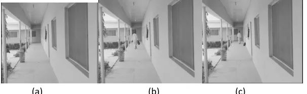
The rgb image was converted to grayscale for faster processing. Figure 3(a) is an empty scene (Background). Figure 3(b) shows objects introduced into the scene (FG). The last frame was shown in Figure 3(c), with the object left by the owner.
(a) (b) (c)
Figure 3.Grayscale image of (a) Frame 10 (b) Frame 150 (c) frame 297(last Frame)
Figures 4(a-c) show the FG of the corresponding frames of Figures 3(a-c).
(a) (b) (c)
Figure 4.Frame Difference FG detection results of Corresponding frames of Figures 3 (a-c)
4.2 Stationary Foreground Object (SFO) Detection Results
The FG object was traced across varying frames to know if it is stationary or otherwise. Table 2 gives the results of centroid in x and y direction as well as its variation across varying frames.
Table 2: Stationary Foreground Object Detection Results Based on Centroid Difference S/No. Frame No. Max. Centroid ‘xi’ Max. Centroid
‘yi’
Centroid Difference dxi dyi
1. 40 0 0 - -
2. 80 186 517 186 517
3. 120 244 440 58 77
4. 160 293 385 49 55
5. 200 351 409 59 24
6. 240 351 408 0 1
where the condition for the set threshold and preset time was satisfied. Hence abandoned object is declared at that point.
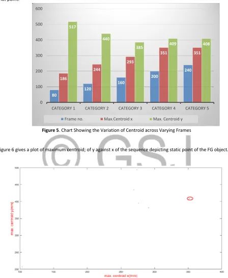
Figure 5. Chart Showing the Variation of Centroid across Varying Frames
Figure 6 gives a plot of maximum centroid; of y against x of the sequence depicting static point of the FG object.
Figure 6:Plot of Centroid(y against x),indicating abandoned object at points(409,351 and 408,351)
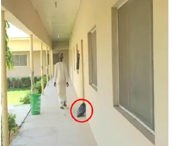
Going by Table 2 and Figures 5 and 6,an abandoned object is detected at frame 240 and hence declared abandoned. Figure 7shows the Frame240,where the abandoned object is detected and declared.
80
120
160
200
240
186
244
293
351 351
517
440
385 409 408
0 100 200 300 400 500 600
CATEGORY 1 CATEGORY 2 CATEGORY 3 CATEGORY 4 CATEGORY 5
Figure 7.Abandoned Objects Detected at Frame 240
5. CONCLUSION
Several techniques of FG detection and SFO detection were reviewed in this work toward achieving the set objectives. This formed the basis for the selection of frame difference method for FG detection and the centroid difference tracking method for SFO detection. Customized database was used for testing/evaluation of the technique. The method gives a better detection of the foreground. The centroid obtained from the FG blobs aided in determining the static or dynamic status of the detected FG objects.
The result obtained indicated a better detection of the abandoned object. The method is limited to simple scenario detection, but will go a long way in minimizing death and injuries in public places. Other researchers should build upon this, so as to handle complex scenarios.
REFERENCES
[1] C. Solomon T. Breckon Fundamentals of Digital Image Processing A Practical Approach with Examples in Matlab. John Wiley & Sons, Ltd.First published 2011.
[2] C. Cuevas, R. Martinez, N. Garcia“Detection of stationary foreground objects: “A survey Computer Vision and Image Understanding”, 2016.
[3] S.S.Sengar, S.Mukhopadhyay“Moving object area detection using normalized self-adaptive optical flow”, - International Journal for Light and Electron Optics,2016.
[4] C. Stauffer, W.E.L.Grimson “Adaptive background mixture models for real-time tracking”, in Computer Vision and Pattern Recognition, IEEE Computer Society Conference on volume 2, IEEE1999.
[5] P.KaewTraKulPong, R.Bowden “An Improved Adaptive Background Mixture Model for Real time tracking with Shadow Detection”, In Proc. 2nd European Workshop on Advanced Video Based Surveillance Systems (AVBS01): Computer Vision and Distributed Processing, Kluwer Academic Publishers,September, 2001.
[6] C.Stauffer, W. E. L.Grimson “Learning patterns of activity using real-time tracking”, IEEE Transactions on Pattern Analysis and Machine lntelligence, vol. 22, no. 8, August 2000.
[7] A. Singh, S.Sawan, M.Hanmandlu, V. K.Madasu, B. C Lovell“An abandoned object detection system based on dual background segmentation”, in Advanced Video and Signal Based Surveillance (AVSS’09), Sixth IEEE International Conference on IEEE, pp. 352–357, 2009.
[9] J. C. S. Miguel, J. M.Mart´ınez.“Robust unattended and stolen object detection by fusing simple algorithms”,in Advanced Video and Signal Based Surveillance(AVSS’08), IEEE Fifth International Conference, pp. 18–25, 2008.
[10] A. Bayona J. C. S. Miguel, J. Martínez “Comparative evaluation of stationary foreground object detection algorithms based on background subtraction techniques”, Video Processing and Understanding Lab .Escuela Politécnica Superior, Universidad Autónoma de Madrid, SPAIN, Advanced Video and Signal Based Surveillance, 2009.
[11] A. Gupta, V.R. Stapute, K.D. Kulat and N.Bokde “Real-time abandoned object detection Using Video Surveillance”, Proceedings of the International Conference on Recent Cognizance in Wireless Communication & Image Processing,Springer India 2016.
[12] R.Singh, S. Vishwakarma, A. Agrawal, M. Tiwari “Unusual activity detection for video surveillance”, in Proceedings of the First International Conference on Intelligent Interactive Technologies and Multimedia, pp. 297–305,2010.