GLOBAL JOURNAL OF ADVANCED ENGINEERING TECHNOLOGIES AND
SCIENCES
MULTIPHYSIC MODEL DEVELOPMENT OF A HYBRID VEHICLE WITH
TWO-WHEEL DRIVE
Nissrine Mhaiti*, Mohammed Radouani, Benaissa El Fahime
*
Equipe de recherche Ingénierie Multidisciplinaire et Systèmes Mécatronique – IMSM Laboratoire de
recherche Mécanique, Mécatronique et Commande – L2MC, University of Moulay Ismaïl, ENSAM
Meknès, Maroc
ABSTRACT
Vehicles are a fundamental part of our daily lives. However, conventional cars are the main source of pollution in the 21st century. For that reason, industries have to concentrate more on alternative energy and transport’s means in order to avoid energy crisis. Environmental worries motivate the world’s automobile industries to change conventional vehicles into low-emission and zero-emission vehicles. So far, the most promising technologies are hybrid vehicles that contain two or many power sources and which we find several architectures.
In this paper, we developed a dynamic model of hybrid vehicle with two-wheel drive and its control unit using AMESim environment. The simulation results of this multidisciplinary system were used for an operating cycle NEDC (New European Driving Cycle) to optimize fuel and battery consumptions.).
KEYWORDS: Hybrid vehicle, two-wheel drive, Multiphysic model, Simulation, AMESim.
INTRODUCTION
It is known, on one hand, that conventional vehicles are the main cause of environment pollution and poor fuel economy despite of providing good performances using the high-energy-density advantages. On the other hand, the high-energy efficiency and the zero environment pollution are advantages of electric vehicles over conventional vehicles. Still, its performances is much less competitive than conventional vehicles, and precisely the operation range per battery charge [1]. Hybrid Electric Vehicles (HEV) that use two power sources, have overcome disadvantages of the two other types of vehicles. Compared to conventional ones, there is more electrical components used in hybrid vehicles, such as electrical machines, power electronics, electronic continuously variable transmissions (CVT). The energy storage devices, such as Li-ion batteries, super capacitors and fuel cells are introduced into the next generation powertrains. In addition to these components or subsystems electrification, conventional internal combustion engines (ICE) and mechanical and hydraulic systems may still be present.
The dynamic interactions between the different components and its multidisciplinary nature make it difficult to analyze a HEV. Each of the design parameters should be carefully chosen to make better fuel economy, enhanced security, ease of exceptional driving dynamics and competitive performance at an acceptable price for the consumer market. Prototyping and testing every combination of design is heavy, expensive, and time consuming. For that reason, modeling and simulation are essential for the evaluation, the prototyping and the analysis of HEV. Thus, in this work, we study different characteristics of this vehicle’s configuration and we propose a model of a HEV with two-wheel drive. The idea is to associate to the classic conventional drivetrain an electric drivetrain and replacing two non-driving wheels by wheel-motors in a perspective of full-hybrid vehicle. This model is under a multi-physics modeling software. We finally present the simulation results comparing to the operating cycle NEDC.
DESCRIPTION OF HYBRID VEHICLE WITH TWO-WHEEL DRIVE
Hybrid electric vehicleA HEV is a vehicle with two or more different powertrains. The most common hybrid vehicles are hybrid electric vehicles involving propulsion system with conventional internal combustion engine and an electric propulsion system [2].
The architecture of a hybrid vehicle is defined as the connection between the components of the energy flow routes and control ports. The HEV architectures are organized into three main classes [6]:
Series hybrid vehicle:
The fuel tank, ICE and the generator are the primary energy source and battery function like the energy bumper. The purpose of the energy storage device is to allow more power to be drawn by the electric motor during more demanding driving conditions (hill climbing, hard accelerations, etc.) [4].
Figure 1. Series hybrid vehicle.
The advantage of this architecture is that the engine operates at a high efficiency, which means a low level of pollutant emissions, but the energy, in this configuration, is loss in the driveline.
Parallel hybrid vehicle:
For the parallel architecture, shown in Fig. 2, two mechanical powers are added together in a mechanical coupling. The ICE is the primary power source and the batteries and the electric motor drive are the energy dumper. Only the engine and the electric motor can control the power flows [5].
Figure 2. Parallel hybrid vehicle.
In this architecture, the loss of energy in the driveline is minimum.
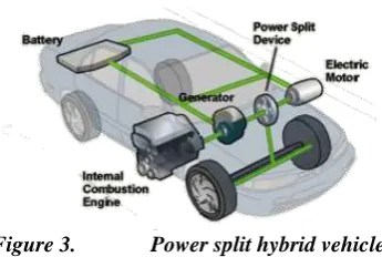
Power split hybrid vehicle:
The Fig. 3 shows the third architecture which is distinguished by the employment of two power couplers: mechanical and electrical. This configuration is the combination of the other two architectures, series and parallel, in order to benefit from advantages of both systems [6].
Figure 3. Power split hybrid vehicle.
The advantages of this configuration is that the power for the wheels or for charging the battery is provided by multiple solutions.
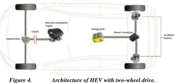
Hybrid vehicle with two-wheel drive
The hybrid vehicle with two-wheel drive, which constitutes our system, is a parallel hybrid vehicle with a different philosophy. The concept of this architecture is to associate to the unmodified conventional thermal power train, a propulsion chain on the rear axle with two in-wheel motors, also called hub motors [7].
Figure 4. Architecture of HEV with two-wheel drive.
Fig. 4 synthetically reflects the general philosophy of the vehicle. It consists of an engine mounted on the front axle, two wheel motors mounted on the rear axle, of an energy pack, power converters and a control unit.
MODELING OF HEV WITH TWO WHEEL-DRIVE
Modeling environment descriptionThe multidisciplinary nature of the hybrid vehicle with two-wheel drive requires a multiphysics model using modeling and simulation tool designed to this purpose.
To implement a blocks diagrams model of the vehicle, we use AMESim (Advanced Modeling Environment for performing simulations) of LMS International, which is a dynamic simulation environment of various engineering fields: mechanical, electrical, thermal systems and physical multidomain systems. Indeed, the models of components of these fields can be combined harmoniously in an easy to use interface. AMESim’s multi-port modeling of physical components as well as its block-diagram approach for control systems enables the coupling of all its libraries together, within a built-in and comprehensive workflow [8].
Internal Combustion Engine’s model
The ICE enables the production of mechanical power from the chemical energy released by the fuel [11]. It allows the drive of the front axle of the vehicle; and it is mainly used for conventional operating mode. The model used of ICE, shown in Fig. 5, is an AMESim model that computes the torque, the emissions (CO, HC, NOx, soot) and the fuel consumption as well as the exhaust gas’s flow rate and the combustion thermal losses.
Figure 5. Model of the Internal Combustion Engine
speed, the number of deactivated cylinders, the reference mode associated with the deactivated combustion mode, the variation of the displacement, and the overconsumption during engine start. It also receives the coolant temperature that is used to determine if the engine is cold or hot.
In-wheel motor and its control circuit
The in-wheel motors are two rotary electric machines incorporated in rear wheels. These electric machines are modeled as permanent magnet synchronous motors (PMSM). The PMSM are used to drive the vehicle's rear axle in full electric operation mode; however, they are also used as a generator or as a motor in conventional operation mode (recuperative braking and deceleration)
Both electric machines have a speed related to the vehicle speed without slippage. In order to establish a general model of PMSM, we need to make a transition from three axes ABC to two axes d-q. To do this rotation transition we use Park's transformation [10].
Using this transform, we could model the control circuit of each electric motor given in Fig. 6:
Figure 6. Model of the electric motor and its control circuit.
Battery’s model
This is the main power source to vehicle propulsion in full-electric mode and it mainly supplies the DC traction inverters. The battery is also used to supply power to the control unit.
The model used of the battery is an internal resistance model, which characterizes the battery with a voltage source and an internal resistance.
The expression of the battery output voltage is as follows:
V = 𝑉0− R ∗ I (1)
Where:
V: is the output voltage (V), V0: is the open circuit voltage (V),
R: is the equivalent internal resistance (Ohm), I : is the input current (A).
The battery consists of banks in serial and parallel arrangements; each battery bank consists of cells [4]. In the example shown in Fig. 7, the number of battery banks in series is Sbank = 4; the number of battery banks in parallel is Pbank = 7; and the number of cells in series per battery bank is Ncell = 3.
The battery is charged either by the electric motor (used as a generator) during braking phases, or by the internal combustion engine (through the electric motor): when the engine is started, if its optimum power is higher than the requested one, the difference can be used to charge the battery.
The Fig. 8 shows the modeled battery for our system.
Figure 8. Model of the battery.
Control unit’s model
In order to minimize the consumption of the battery, we introduce in our model a control unit, Fig. 9, that analyses various information received from other elements of the vehicle:
• Acceleration, braking commands and gearbox ratio from the driver • Rotary velocity from the electric motor
• Rotary velocity from the engine
• State of charge and voltage from the battery • And the vehicle speed
Figure 9. Model of the control unit.
The control unit manages the power requested to the engine and the electric motor and in function of the cooling temperature received "Twater". It calculates the value of the overheating combustion coefficient "Ktherm".
Simulation parameters and results
The interconnection of all sub-models, which represent the system, allows the assembly of the complete model of the hybrid vehicle with two drive wheels shown on Fig. 10.
Figure 10. The complete model of the HEV with two wheel drive.
Parameters values of the simulation
The parameters used in simulation are summarized in Table below:
Table1. Parameters values of the vehicle’ submodels
Component Parameter Value
Internal Combustion Engine
Engine type Spark ignition
Swept volume 1.6 L
Fuel specific heating value 42700 kJ/kg
Maximum torque 80 Nm
Electric motor
Permanent magnet flux linkage at reference
temperature 0.07 Wb
Maximum RMS current 50 A
Stator cyclic inductance on Park’s d axis 0.00175*0.9 H Stator cyclic inductance on Park’s q axis 0.00175*1.1 H
Battery
Potential 144 V
Number of cells in series per battery bank 5 Number of battery bank in parallel 1 Number of battery bank in series 20
Gearbox
Maximum Coulomb friction torque on
secondary shaft 300 Nm
Powered axle gear ratio 4.25
Transmission gear ration (1st gear) 3.5 Transmission gear ration (2nd gear) 2 Transmission gear ration (3rd gear) 1.4 Transmission gear ration (4th gear) 1 Transmission gear ration (5th gear) 0.85
Vehicle
Total vehicle mass 1.4 tonne
Wheel inertia 0.75 kg.m²
Wheel rim diameter 15 in
Air penetration coefficient (Cx) 0.31 Vehicle active area for aerodynamic drag 2.1 m²
The simulation results
Using the multiphysic modeling approach under LMS AMESim environment, we can simulate the input and output variables of every component of our system’s model. These variables can be visualized in evolution curves and compared to those of real models.
To validate the results of the modelled HEV a simulation of model was performed and the results were compared to those of the New European Driving Cycle (NEDC), presented in Fig. 11.
Figure 11. Speed profile and speed set point
The principle of this cycle is a "scenario" consisting of acceleration, deceleration and constant speed bearings over a period of 20 minutes. For more details about driving cycles see [12].
The simulation result of our system’s speed is shown in Fig. 12:
Figure 12. Speed profile and speed set point
By merging the two speed curves, we obtain the curve in Fig. 13.
In this figure, we can see more closely that the speed of the vehicle model follows the speed's set point given by the NEDC cycle. In this cycle, when the vehicle speed is low, only electric machines operate. The vehicle is in electric mode. As speed increases, the power required is large and the engine is operated; then the vehicle is in hybrid mode.
Figure 14. ICE model’s torque compared to torque command
In Fig. 14, we have compared the torque of our model system to the torque command giving by the control unit. In the Fig.15, we compare the torque result of the in-hub motor of our system to the torque command from the control unit.
Figure 15. EM model’s torque compared to torque command
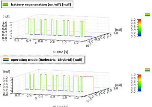
Finally, the Fig. 16 presents a comparison between battery regeneration (when it should be recharged) and the operating mode of the vehicle (electric or hybrid):
The battery is charged either by the electric motor (used as a generator) during braking phases, or by the internal combustion engine (through the electric motor): when the engine is started, if its optimum power is higher than the requested one, the difference can be used to charge the battery.
CONCLUSION
In this paper, we compared existing hybrid architectures and presented advantages and weaknesses of each one. We identified and studied operating characteristics of each component of the parallel hybrid vehicle with two wheel-drive. Then we developed a physical model of this system using a multiphysic modeling and simulation tool.
Moreover, we could simulate and analyze the vehicle parameters due to the interconnection of these components. In addition, we were able to validate the dynamic parameters of our system and compare these parameters with those of a normalized driving cycle: NEDC cycle.
REFERENCES
[1] C.D. Anderson and J. Anderson, “Electric and hybrid cars/ history”, Mcfarland & Company, Inc. publishers, Second edition, ISBN 978-0-7864-3301-8 2010, pages 269.
[2] G. Bailly, “ Simulation multi-domaines d'un système de propulsion hybride électrique sous l'environnement matlab/simulink ”, thesis presented at école de technologie Supérieure of Montréal, Canada 2006.
[3] N. Mhaiti, M. Radouani, B. El Fahime, “Multi-Physic Modeling and Simulation of a Hybrid Vehicle with Range Extender”, International Journal of Engineering Sciences & Research Technology, Volume 3, Issue: 4, April 2014, Pages 7058-7062.
[4] B.T. Fijalkowski, “Automotive Mechatronics: Operational and Practical Issues”, ISBN 978-94-007-0408-4, Volume I, 2011, pages 612.
[5] I. Husain, “Electric and Hybrid Vehicles: Design Fundamentals”, ISBN 0-8493-1466-6, published in the Taylor & Francis e-Library, 2005, pages 373.
[6] M. Ehsani, Y. GAO, A. Emadi, "Modern Electric, Hybrid electric, and Fuel cell vehicles/ Fundamentals, theory, and Design", ISBN 978-1-4200-5398-2 (Hardback), Second Edition, 2010, by Taylor and Francis Group, Power electronics and applications series.
[7] Y. Hung, C. Wub, “A combined optimal sizing and energy management approach for hybrid in-wheel motors of EVs”, Applied Energy, Elsevier, 2015, pages 260–271.
[8] LMS International, http://www.lmsintl.com/imagine-amesim-1-d-multi-domain-system-simulation [9] I.Y. Onel, M.E. Benbouzid, “Induction Motor Bearing Failure Detection and Diagnosis: Park and
Concordia Transform Approaches Comparative Study”,Mechatronics, IEEE/ASME Transactions, Volume: 13, Issue: 2, April 2008
[10]V. Reinbold, “Méthodologie de dimensionnement d'un moteur électrique pour véhicules hybrides : optimisation conjointe des composants et de la gestion d'énergie”, thesis presented at Université de Grenoble, 2014. French.
[11]J.B. Heywood, “Internal Combustion Engine Fundamentals”, ISBN 0-07-028637-X, McGraw-Hill series in mechanical engineering Inc., 1988.