IJEDR1904020 International Journal of Engineering Development and Research (www.ijedr.org) 112
Analysis Of Dynamic Behaviour Of Rc Elevated
Water Tank
1Ravi S. Gupta, 2Dr. Vikram. A. Patil, 3Mr.Somangoud Takkalki 1Student, 2Project Guide, 3Head of Department
B.R. HARNE College of Engineering
_____________________________________________________________________________________________________
Abstract - As known from the very past experiences, elevated water tanks were collapsed or heavily damaged during earth quakes throughout the world. These unusual events showed that the supporting system of the elevated tanks has more critical importance than the other structural types of tanks. The main aim of this project is to understand the seismic behaviour of the elevated water tank and finite element technique is used to investigate the seismic effect of the elevated reinforced concrete water tank with consideration and modelling of impulsive and convective water masses inside the container in Two Mass Model as per IS: 1893(part 2)-2002. The behaviour of elevated water tanks with Shaft staging pattern is analysed using from the codes IS 1893 (part 1): 2002 and IS 1893 (part 2): 2002.In addition analysis is done manually as IS standards and Finite element model and result are compared. Six cases are chosen for the analysis for Zone II and Zone V for Hard, medium and soft soil condition and there Base Shear and Overturning moments results are compared with SAP result. Finally the compared results have been presented in the form of graphs and tables.
keywords - Elevated water tank, Design, Analysis, Comparative study.
_____________________________________________________________________________________________________
I.INTRODUCTION
Water is human basic needs for daily routine. Actual water distribution depends on design and type of a water tank in certain area. An elevated water tank is a large water storage container constructed for the purpose of holding water supply at certain height to Pressurization the water distribution system. Many new ideas and innovations have been made for the storage of water and other liquid materials in different forms . There are many different ways for the storage of liquid such as underground, ground supported, elevated etc,. Liquid storage tanks are used extensively by municipalities and industries for storing water, inflammable liquids and other chemicals. Thus Water tanks are very important for public utility and for industrial structures.
1. Sloshing
Liquid sloshing is a kind of wave motion inside a partially filled tank. The sloshing phenomenon is of great theoretical and practical importance in coastal and offshore engineering with regard to the safety of sea transport of oil and liquefied natural gas (LNG). Under external excitations that are of large amplitude or near the natural frequency of sloshing, the liquid inside a partially filled tank is prone to violent oscillations and large impact pressure on the tank.
The cycle time for one floor with the use of conventional formwork is minimum 3-4 weeks. Also, the block or Brick work and plastering is needed in order to get the finished surface. This takes more time and skilled labours too. This ultimately increases the time required for the completion of the project.
2. Seismic Analysis of Over Head Water Tank.
Analytical studies dealt with the hydrodynamics of liquids in rigid tanks resting on rigid foundations. It was shown that a part of the liquid moves in long-period sloshing motion, while the rest moves rigidly with the tank wall.
Tanks supported on flexible foundations, through rigid base mats, experience base translation and rocking, resulting in longer impulsive periods and generally greater effective damping. These changes may affect the impulsive response significantly. The convective (or sloshing) response is practically insensitive to both the tank wall and the foundation flexibility due to its long period of oscillation. Failure of tanks during Chilean earthquake of 1960 and Alaska earthquake of 1964 led to beginning of many investigations on seismic analysis of liquid storage tanks. Following two aspects came to forefront.
a) Due consideration should be given to sloshing effect of liquid and flexibility of container wall while evaluating the seismic force of tank.
b) It is recognized that tanks are less ductile and have low energy absorbing capacity and redundancy compared to the conventional building systems.
3. Lumped Mass Modal Method (IS 1893:2002):
For the purpose of this analysis, elevated tanks shall be regarded as systems with a single degree of freedom with their mass concentrated at their centre of gravity. The damping in the system may be assumed as 5 percent of the critical for concrete The Time period T, in seconds, of such structure shall be calculated from the following formula.
𝑇 = 2𝜋√𝑚k
𝑠 …….. (3.1)
Where,
IJEDR1904020 International Journal of Engineering Development and Research (www.ijedr.org) 113 ks= lateral stiffness of the staging.
Using time period T calculated in above and 5 percent damping, the spectral acceleration shall be read off from the average acceleration spectra given in Figure.3.2 The design horizontal seismic coefficient.
The lateral force shall be taken equal to:
αh* W …….. (3.2)
Where,
αh= Design horizontal seismic coefficient
W= Seismic Weight.
The design shall be worked out both when the tank is full and when empty. When empty, the weight W used in the design shall consist of the dead load of the tank and one-third the weight of the staging. When full, the weight of liquid is to be added to the weight under empty condition.
Design horizontal seismic coefficient shell be calculated W by response spectra method
αh= β.I.F0 (Sa/g) ... (3.3)
Here:
β = a coefficient depending upon the soil foundation I = a factor depend upon the importance of the structure F0= seismic zone factor for average acceleration spectra
Sa/g = average acceleration coefficient as read from the Fig.3.2 for above time period T And 5% damping.
4. Two Mass Modal Method (Is 1893: 2002) (Part 2 Draft)
Most elevated tanks are never completely filled with liquid. Hence a two-mass idealization of the tank is more appropriate as compared to a one mass idealization. Failure of tanks during Chilean earthquake of 1960 and Alaska earthquake of 1964 led to beginning of many investigations on seismic analysis of liquid storage tanks and this aspect came to forefront that consideration should be given to sloshing (convective) effect of liquid and flexibility of container wall while evaluating the seismic force of tank.
(1) Impulsive mode
Time period of impulsive mode, in seconds, is given by Ti=2𝜋√𝑚𝑖+𝑚𝑠
𝑘𝑠 …….. (3.8)
Where,
mi= impulsive mass,
ms= mass of container one-third mass of staging, and ks= lateral stiffness of the staging.
(2) Convective mode
Time period of convective mode, in seconds, is given by Tc=2𝜋√𝑚𝑐
𝑘𝑐 …..… (3.9)
Parameters of circular tank i.e. Impulsive mass (mi), convective mass (mc), height at which impulsive mass is acting (hi), height
at which convective mass is acting (hi), height at which impulsive mass is acting considering base pressure (hi*), height at which
convective mass is acting considering base pressure (hc*) and convective stiffness (kc) based on h/D ratio
Fig 1. Base Shear in lumped mass model
II.OBJECTIVE
To study behaviour of elevated circular R.C. water tanks supported on shaft staging under earthquakes,.
Seismic analysis of elevated circular R.C. water tanks supported on shaft staging considering lumped mass model as per IS 1893-Part 1.
Seismic analysis of elevated circular R.C. water tanks supported on shaft staging considering two mass model as per draft code 1893-Part 2, (2005).
IJEDR1904020 International Journal of Engineering Development and Research (www.ijedr.org) 114
III.LITERATURE REVIEW
Here various methods for Seismic analysis of elevated water tanks parameters such as spring mass model parameters, time period, base shear, base moment, hydrodynamic pressure, sloshing height of liquid was presented by various eminent persons from different parts of the world were discussed.
A. M. Kalani and S. A. Salpekar: They have observed that for different staging configuration, results gives a comparative study between conventional and matrix methods of analysis for staging of overhead water tanks. In this report design have been carried out using computer program economic dimensions. The geometrical dimensions of the system remains the same except that the number of columns considered as 6, 8 and 10 with inclination of column varies with 0°, 30° and 60°. Here, straight bracings are provided at three levels, which divide the staging in four panels.
Sameer U. Sajjad and Sudhir K. Jain: This paper Presents an improved procedure for lateral-load analysis of polygonal braced staging with columns fixed at foundation level. The axial force in the columns is obtained assuming that it is proportional to the distance of the column from the bending axis of the staging. The shear in bracing is then obtained by considering vertical equilibrium of structural units isolated from the staging. Finally, the shear in columns is obtained from moment equilibrium in the plane of bending. The point of inflection is assumed at mid spans of columns in the intermediate panels and bracing girders.
Veletsos A.S and Shivakumar P: studied the response to horizontal ground shaking of a rigid cylindrical tank containing an in viscid liquid with a continuous vertical variation in density is presented. In addition to the free vibrational sloshing characteristics of the liquid, the responses examined include the vertical displacements at the free surface, and the impulsive and convective components of the hydrodynamic wall pressures and associated tank forces. The equations of motion for the system are formulated for an arbitrary variation in liquid density but the solutions presented are for a density that increases exponentially from top to bottom.
Aliakbar Qutubuddin and Ali Deepa P. Telang: They have Effects of hydrodynamic forces on tank walls are calculated. History of earthquake reveals that it have caused numerous losses to the life of people in its active time, and also post-earthquake time have let people suffer due to damages caused to the public utility services. Either in urban or rural areas elevated water tanks forms integral part of water supply scheme, so its functionality pre and post-earthquake remains equally important.
Sekhar Chandra Dutta: has review of past earthquakes reveals damage/failure of important lifeline facilities like elevated water tanks in recurrence, leading to serious hazards even after the event. In the context of such hazards indicating deficiencies in the existing seismic design strategy of such structures, dynamic characteristics of elevated tanks supported by cylindrical shaft (shaft staging) are comprehensively studied in their first part of investigation. The same is made through analytical formulations developed and validated by rigorous finite element analysis and small-scale experimentation. Subsequent examination on seismic response of representative tanks indicates that the columns of the frame-supported tanks (tanks with frame staging) and the wall of the shaft-staging of such reinforced concrete (R.C.) tanks are susceptible to tension, particularly at tank empty condition.
IV.METHODOLOGY
IJEDR1904020 International Journal of Engineering Development and Research (www.ijedr.org) 115 Fig 2. Elevated Water Tank.
V.CALCULATION:
VI.RESULT
Results of base shear and overturning moments of lumped mass model and two mass model are shown below, and those results are compared with SAP result.
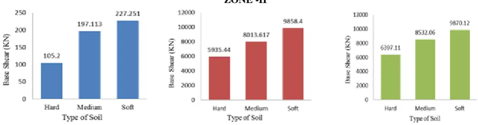
ZONE -II
Fig 3. Base Shear in lumped mass model Fig 4. Base Shear in two mass model Fig 5.Base Shear in SAP result.
Components Calculations
Weight (kN)
Top Dome
Radius of dome,r1 = [((8.8/2)2 / 1.69) + 1.69)] / 2 = 6.57
2 x π x 6.57 x 1.69 x (0.12 x 25) 209.3
Top Ring Beam π x (8.6 + 0.25) x 0.25 x 0.30 x 25 52.1
Cylindrical Wall π x 8.8 x 0.20 x 4.0 x 25 552.9
Bottom Ring Beam π x (8.6 + 0.5) x 0.5 x 0.30 x 25 107.2
Circular Ring Beam π x 6.28 x 0.50 x 0.60 x 25 148
Bottom Dome
Radius of dome, r2 = [(6.28/2)2 /1.40) + 1.40] / 2 = 4.22
2 x π x 4.22 x 1.40 x 0.20 x 25 185.6
Conical Dome
Length of Cone, Lc = (1.652 + 1.412)1/2 = 2.17
π x ((8.80 + 6.28) / 2.0) x 2.17 x 0.25 x 25 321.3
Water
[ (π x 8.62 x 3.7 /4) +( π x1.5( 8.62 + 5.632 + (8.6 x 5.63)) / 12 - (π
IJEDR1904020 International Journal of Engineering Development and Research (www.ijedr.org) 116 Fig 6.Overturning Moment in Fig 7. Overturning Moment in Fig 8. Overturning Moment in SAP
lumped mass model two mass model result.
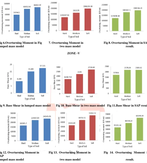
ZONE -V
Fig 9. Base Shear in lumped mass model Fig 10. Base Shear in two mass model Fig 11.Base Shear in SAP result.
Fig 12. Overturning Moment in Fig 13. Overturning Moment in Fig 14. Overturning Moment in SAP
lumped mass model two mass model result.
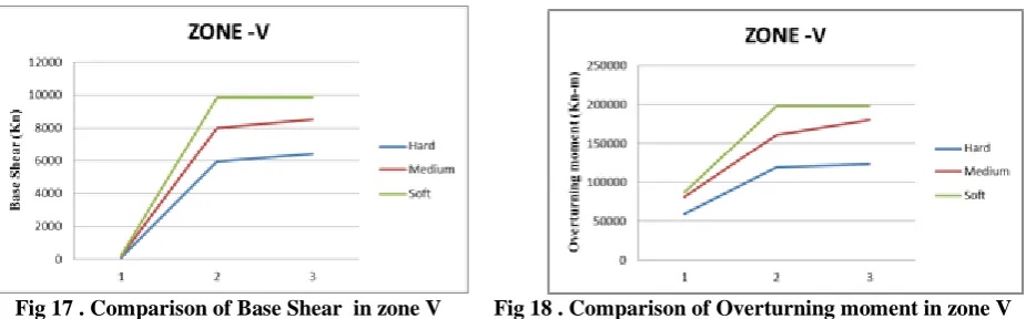
IJEDR1904020 International Journal of Engineering Development and Research (www.ijedr.org) 117
Fig 17 . Comparison of Base Shear in zone V Fig 18 . Comparison of Overturning moment in zone V
VII.CONCLUSION
From the present studies we can observe that, base shear & overturning moments in Two Mass model are comparatively less in lumped mass model. Idealization of water tank as single degree of freedom system is not appropriate for seismic analysis of water tanks with large capacity - two mass idealization should be used for dynamic analysis of water tanks.
REFERENCES
[1] A. M. Kalani S. A. Salpekar (1978), ―A comparative study of different methods of analysis for staging of elevated water tanks‖, Indian Concrete Journal, JulyAugust – 1978, Pg No.210-216.
[2] Sameer U. Sajjad and Sudhir K. Jain Lateral Load Analysis of Frame Staging’s for Elevated Water Tanks, Journal of Structural Engineering, Vol.120, No. 5, pp. 1375-1394.
[3] Veletsos A.S and Shivakumar P;. Tanks containing liquids or solids, S.A, Computational mechanics publication, Southampton, U. K, Boston, U.S.A., (1997).