ANALYSIS OF OPEN LOOP AS WELL
AS CLOSED LOOP V/F CONTROLLED
INDUCTION MOTOR DRIVE
NEHA MAROTHIADepartment of Electrical Engineering, Institute of Technology Nirma University, Sarkhej Gandhinagar Highway,
Ahmedabad, Gujarat 382481, India [email protected]
SIDDHARTHSINGH K. CHAUHAN
Department of Electrical Engineering, Institute of Technology Nirma University, Sarkhej Gandhinagar Highway, Ahmedabad, Gujarat 382481, India
Abstract:
This Paper presents scalar control technique of induction motor drive whereby controlling the frequency and amplitude of stator voltage of induction motor so as to make the v/f ratio constant. The most basic requirement for this v/f control scheme is the PWM inverter. This paper presents both open loop and closed loop control of induction motor drive. The simulations of both open loop and closed loop v/f control method have been carried out using MATLAB/SIMULINK environment. Under this simulation, different loads have been given to the drive to observe the rotor speed.
Keywords: Induction motor(IM), Voltage source inverter (VSI), Sinusoidal pulse width modulation (SPWM) control scheme, Open loop v/f control, Closed loop v/f control.
1. Introduction
Due to recent advances in power electronic switching devices, electric drives have got a lot of importance [1]. In most of the applications AC machines are being preferred rather than DC machines. The reason being that AC machines are simple to implement, have robust construction and do not have any commutator [2]. In conventional open loop control method, the stator resistance has more dominant voltage drop compared to the voltage drop which occurs in production of main flux at low frequencies. Hence at low frequencies the stator resistance voltage drop must be taken into consideration. The simplest method to compensate the stator resistance is by boosting the stator resistance voltage drop [3]. However, it is easy to get flux saturated but it is not easy to get boosted voltage [3,4,5]. The methods to boost the voltage needs machine parameters which is quite complex [1, 4]. The open loop scalar control method cannot maintain speed accuracy both at low as well as high frequency and suffer oscillations also at light load conditions [1,7,4,6]. Many solutions regarding this instability problem have been carried out [8,6]. To overcome these limitations, an outer loop is connected to compare the reference speed with actual speed and feed that error into PI controller. Constant v/f method is widely suggested for constant and variable speeds of induction motor [9]. The power electronics based drives, especially IGBT based Pulse Width Modulation (PWM) inverters for efficient frequency changing made their use more frequent. Different modulation techniques have been used to obtain variable voltage and variable supply. The most extensively used PWM technique is carrier based PWM scheme for three phase voltage source inverters. The PWM based firing provides best smooth v/f control of an induction motor by controlling both output voltages of inverter and frequency simultaneously. In this paper, three phase two level voltage source inverter has been used with sinusoidal PWM technique because it provides harmonic elimination, four quadrant operation and smooth transition of v/f in both the open and closed loop control applications [10]. The three phase induction motor drives have got some new developments and features in it which are as follows:
1. Possess IGBT based PWM inverters for efficiently frequency changeover and minimized losses with high power density.
All these features have caused widespread use of induction motors hence they are called as Racehorse of the Industry
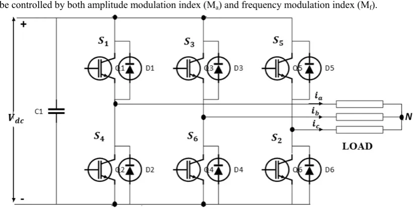
2. Three Phase Two Level Inverter
The main purpose of this inverter is to provide three phase voltage source where the phase, frequency, amplitude of the voltages should always be controllable. The primary task of this VSI is to convert fixed dc into variable three phase voltage and frequency. The inverter has six switches from S1 to S6. The switches of same leg cannot be switched on simultaneously because then it will result in short circuit across the dc link and cannot be switched off simultaneously otherwise it will result in voltages which will depend upon respective line current polarity [11]. To generate a given voltage waveform inverter moves from one state to another. Thus the output voltage achieves +Vi, 0, -Vi hence generating discrete voltages. In order to generate this given waveform, the selection of states is done by choosing the modulating technique which is SPWM technique here.
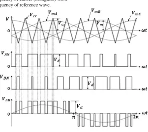
As we know the principle of PWM technique is by adjusting the on and off periods of inverter, we can control the ac output voltage provided fixed dc is given as a supply. This method of controlling is known as PWM control. Fig. 1. Shows the three phase sinusoidal modulating waves which are , , and is the high frequency triangular carrier wave. The amplitude modulation index controls the fundamental frequency component in inverter output voltage which is given by
Ma =
(1)
Where Ma = modulation index = Reference voltage = triangular carrier wave
And the normalized carrier frequency which is also known as frequency modulation index is given by
Mf = (2)
Where = frequency of carrier (triangular) wave
= frequency of reference wave.
which is across phase a with respect to negative dc link N is equal to (DC voltage). Now when < then Switch S1 is turned off and switch S4 becomes on which gives = 0 as can be seen from Fig. 2. Thus waveform has two levels hence the inverter is known as two level inverter. Also while doing this, it should be kept in mind that always provide some blanking time while turning on and off the switches to prevent any kind of short circuits [12]. In SPWM scheme the amplitude and frequency of line voltage which is determined by
= - (3)
can be controlled by both amplitude modulation index (Ma) and frequency modulation index (Mf).
Fig. 2: Three Phase Two Level Inverter
3. Open Loop V/F Control Topology
It is the most well-known technique for speed control which is broadly utilized in view of its straightforwardness. Conventionally we use 50 Hz control supply for steady speed applications and for movable speed drive, it is evident to control frequency. However, voltage is required to be controlled in relative with frequency to make stator flux consistent if stator resistance is neglected. The power circuit comprises of a DC source and PWM voltage-based inverter [13]. The PWM converter is converged with the inverter block. A few issues experienced in the operation of this open loop drive are accompanying:
• The speed of the motor can't be controlled accurately, due to the fact that the rotor speed will not be exactly equal to the synchronous speed, it will be less than the synchronous speed while synchronous speed is the main control variable
.
• The slip speed which is difference between the synchronous speed and the electrical rotor speed, can't be kept constant, as the rotor speed is not measured in this scheme. This can lead to operate in the unstable area of the torque-speed characteristics.
• The impact of the above can make the stator current exceed the rated current by an extensive sum thus causing failure of the inverter-converter combination.
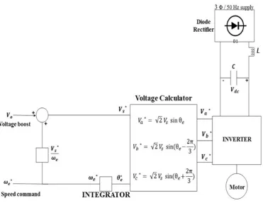
Fig. 3: Basic Open Loop V/f control block diagram
Fig. 3. shows the basic block diagram of open loop volts/Hz speed control method. The circuit consists of a diode rectifier with three phase ac supply, filter and a PWM voltage source inverter. Here, we are neglecting the small slip frequency and controlling the reference velocity ∗ . The actual velocity is added to the
reference velocity ∗ of the motor to result in reference synchronous frequency, ∗. This frequency is to be
multiplied with the number of pole pairs Pp to get reference output frequency, ∗of the inverter and this
frequency is also used as an input to voltage regulator. The phase voltage Vs*command is directly generated by frequency command so that the air gap flux remains constant. Also this ∗is integrated further to get an
angle ∗ through which the corresponding sinusoidalphase voltages ( ∗, ∗, ∗) are being generated as per
following equations: -
∗ √2 sin (4)
∗ √2 sin 2
3 (5)
∗ √2 sin ) (6)
Table 1. Simulation Parameters
S. No PARAMETERS RATING
1. Rated Voltage 400 V
2. Rated Frequency 50 Hz
3. Rated Power 4000 VA
4. Stator Resistance 1.405 ohm
5. Stator Inductance 0.005839 H
6. Rotor Resistance 1.395 ohm
7. Rotor Inductance 0.005839 H
8. Moment of Inertia 0.0131 Kg.m2
9. Pole Pair 2
10. DC link Voltage 560 V
3.1. Simulation Results
Fig. 4: Stator line voltage ( in an open loop model [X axis: 0.02 sec/div; Y axis: 200V/div]
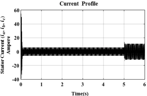
Fig. 5: stator current ( , , in an open loop model
Fig. 6: stator current of all phases ( , , in an open loop model
[X axis: 0.05 sec/div; Y axis: 20 Ampere/div]
Fig. 7: stator current ( in an open loop model [X axis: 0.1 sec/div; Y axis: 20 Ampere/div]
Fig. 9: Variation of Electromagnetic torque with respect to change in load [X axis: 1 sec/div; Y axis: 10 Nm/div]
From the above results we can see that due to the SPWM technique the magnitude of inverter output voltage (Fig. 4.) has been maintained constant i.e., 560V. The behavior of stator current (Fig. 5.) is distorted and non-sinusoidal which indicates high amount of THD. Fig. 6. is zoomed in view of all three phases of stator current. Fig. 7. shows the stator current of single phase ( which indicates that as the load is given at 5 secs, the magnitude of stator current increases. The speed is controlled as can be seen from Fig. 8., however as we are giving load of 20 N-m at 5 seconds then speed tumbles down and doesn't return to its original speed. The variation of electromagnetic torque with respect to change in load can be seen from Fig. 9. The torque profile is not smooth and thus does not maintain constant torque.
Thus, in order to achieve constant torque and sinusoidal current profile irrespective of any variation in load, we are moving towards closed loop V/F control method.
4. Closed Loop V/F Control Topology
The basis of constant V/F speed control of induction motor is to apply a variable magnitude and variable frequency voltage to the motor. Both the voltage source inverter and current source inverters are used in adjustable speed ac drives [14]. The following block diagram shows the closed loop V/F control using a VSI. A speed sensor or a shaft position encoder is used to obtain the actual speed of the motor . It is then compared to a reference speed *. The difference between the two generates an error and the error so obtained is processed in a Proportional controller and its output sets the inverter frequency.
The synchronous speed * obtained by adding actual speed and slip speed * determines the inverter frequency. The reference signal for the closed-loop control of the machine terminal voltage is generated from frequency. Also the synchronous speed is processed through block which is used to maintain volts/hertz constant and generates the phase voltages correspondingly using the three equations (4), (5), (6).
4.1. Simulation Results
Fig. 11: stator line voltage ( of a 3ϕ IM [X axis: 0.1 sec/div; Y axis: 150 V/div.]
Fig. 14: Variation of Electromagnetic torque due to sequential change in load [X axis: 1 sec/div; Y axis: 10 N-m/div.]
Fig. 11. shows the stator line voltage of inverter in closed loop model which maintains its magnitude constant due to the SPWM technique. As the load of 20 N-m is given at 4 secs, the magnitude of all three phases of stator current ( , , increases which is shown in Fig.12. But in closed loop model the current profile is sinusoidal and smooth due to low THD. The variation in rotor speed due to step change in load torque can be seen from Fig. 13. which signifies that as the load of 20 N-m and 30 N-m is given at 4 secs and 7 secs, the speed takes a dip but returns back to its original speed thus maintains a constant speed throughout. The variation of Electromagnetic torque due to change in load is shown in Fig. 14. Initially the motor runs at no load thus torque remains constant but as the load of 20 N-m and 30 N-m is given at 4 and 5 secs respectively, the torque increases and remains constant throughout.
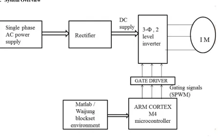
5. System Overview
The Fig. 15. gives the schematic diagram of overall system review of the V/F controlled induction motor drive using ARM-Cortex. First, the rectifier has been given Three phase AC supply. The DC link obtained through the rectifier is given to three phase two level inverter. After this, the sinusoidal pulses (SPWM) are being generated with the help of Waijung in Matlab environment. These pulses are given to ARM-CORTEX microcontroller through which gating pulses (SPWM) will be given to Gate driver of the inverter. The gate driver will drive the switches of the inverter. Finally, the output of the inverter is connected to three phase Induction Motors.
6. Conclusion
This paper presents the implementation of v/f scheme for the induction motor drive. This method has been studied for both the open loop and closed loop models and superior results have been achieved in closed loop model. Initially the motor was started at a reference speed and a constant load torque. Then the load torque was varied and according to that the rotor speed responded. The speed was taken as a feedback and the error in the speed was calculated and the frequency was adjusted accordingly by proportional controller. This corrected frequency is given to the voltage source inverter. Simultaneously the voltage is varied such that the V/f ratio remains constant for any value of frequency. Hence we are able to achieve constant speed for different loading conditions.
References
[1] M.S. Aspalli.1, Asha.R2, P.V. Hunagund,” Three Phase Induction Motor Drive Using Igbts and Constant V/F Method”, International Journal of Advanced Research in Electrical, Electronics and Instrumentation Engineering Vol. 1, Issue 5, November 2012.
[2] Rodolfo Echavada, Sergio Horta, Marc0 Oliver,” A Threephase motor drive using IGBT‟ s and Constant V/F speed control with slip regulation”, 0- 7803-3071-4/95 1995 IEEE.
[3] A. Oteafy, J. Chiasson, ‘‘A Study of the Lyapunov Stability of an Open- Loop Induction Machine IEEE Transactions on Control Systems Technology,’’ Vol. 18, No. 6, Nov. 2010, pp. 1469 – 1476.
[4] A. Munoz-Garcia, T.A. Lipo, D.W. Novotny,‘‘A new induction motor V/f control method capable of high-performance regulation at low speeds, ’’ Vol. 34, No. 4, July/August 1998, pp. 813 – 821.
[5] Wei Chen; Dianguo Xu; Rongfeng Yang; Yong Yu; Zhuang Xu ‘‘A novel stator voltage oriented V/F control method capable of high output torque at low speed,’’ International Conference on Power Electronics and Drive Systems, PEDS2009, 2-5 Nov. 2009, pp 228 – 233.
[6] Y. Q. Xiang, ‘‘Instability compensation of V/Hz PWM inverter-fed induction motor drives,’’ in Conf. Rec. IEEE IAS Annu. Meeting, vol. 1, Oct. 1997, pp. 613-620.
[7] A. M. Trzynadlowski, Control of Induction Motors. Academic Press, CA, USA, 2001.
[8] C.J. Francis, H. Zelaya De La Parra, ‘‘Stator resistance voltage-drop compensation for open-loop AC drives,’’ Electric Power Applications, IEE Proceedings, Vol. 144, No. 1, January 1997, pp.21 - 26.
[9] Ku. Trupti Deoram Tembhekar “A constant v/f open loop and closed loop speed control of a three phase induction motor drive”. [10] F. Blaabjerg, J. K. Pedersen, and P. Thgersen, Improved modulation techniques for PWM-VSI drives, IEEE Trans. Ind. Electron. , vol.
44, pp. 8795, Feb. 1997.
[11] Keliang Zhou and Danwei Wang, "Relationship between space-vector modulation and three-phase carrier-based PWM: a comprehensive analysis [three-phase inverters]," in IEEE Transactions on Industrial Electronics, vol. 49, no. 1, pp. 186-196, Feb
2002.
[12] K. Basu, J. S. S. Prasad, and G. Narayanan, Minimization of torque ripple in PWM ac drives, IEEE Trans. Ind. Electron. , vol. 56, no. 2, pp. 553558, Feb. 2009.
[13] Dr. Bimal K. Bose "Modern Power Electronics and AC Drives" New York: IEEE Press, 1996.
![Fig. 6: stator current of all phases (�� , �� , �� � in an open loop model [X axis: 0.05 sec/div; Y axis: 20 Ampere/div]](https://thumb-us.123doks.com/thumbv2/123dok_us/9669919.1494906/6.595.154.445.506.683/fig-stator-current-phases-open-loop-model-ampere.webp)
![Fig. 9: Variation of Electromagnetic torque with respect to change in load [X axis: 1 sec/div; Y axis: 10 Nm/div]](https://thumb-us.123doks.com/thumbv2/123dok_us/9669919.1494906/7.595.156.440.78.255/fig-variation-electromagnetic-torque-respect-change-load-axis.webp)
![Fig. 12: stator current of all three phases of a 3ϕ IM [X axis: 0.05 sec/div; Y axis: 10 Amperes/div.]](https://thumb-us.123doks.com/thumbv2/123dok_us/9669919.1494906/8.595.155.440.530.740/fig-stator-current-phases-im-axis-axis-amperes.webp)