www.ijiarec.com
Volume-5 Issue-1
International Journal of Intellectual Advancements
and Research in Engineering Computations
Efficient routing protocol for MANET using
STP and BRM
First A.Muthumuniyandi, second G.Prabhu, Third A.Navinkumar, Fourth C.Ranjitha, Fifth V.Selina, Sixth K.Mahendhrakan Assistant Professor,department of ECE,
Hindusthan institute of technology,
ABSTRACT:
Manet routing protocols are designed based on the assumption that all nodes cooperate without maliciously disrupting the operation of the routing protocol. aodv is a reactive manet routing protocol that is vulnerable to a dramatic collapse of network performance in the presence of black hole attack. the paper introduces a new concept of self-protocol trustiness (spt) in which detecting a malicious intruder is accomplished by complying with the normal protocol behavior and lures the malicious node to give an implicit avowal of its malicious behavior. we present a blackhole resisting mechanism (brm) to resist such attacks that can be incorporated into any reactive routing protocol. it does not require expensive cryptography or authentication mechanisms, but relies on locally applied timers and thresholds to classify nodes as malicious. no modifications to the packet formats are needed, so the overhead is a small amount of calculation at nodes, and no extra communication. using ns2 simulation, we compare the performance of networks using aodv under black hole attacks
with and without our mechanism to saodv, showing that it significantly reduces the effect of a blackhole attack.
I.
INTRODUCTION
a mobile ad hoc network (manet) is a decentralizedinfrastructureless network in which nodes cooperate to forwarddata from a source to a destination. each node in a manetacts both as a router and as a host. several routing protocolshave been designed for manets to optimize network routing performance. the major issues involved in designing a routing protocol for manet are node mobility, bandwidthconstrained and error prone wireless channel, resource constrainednodes, and dynamic changing of the network topology.
manet routing protocols can be classified as proactive orreactive routing protocols. in proactive (table-driven) routingprotocols, each node maintains one or more tables containingrouting information to every other node in the network. Whilein reactive (on-demand) routing protocols, routes are created
371
whenever a source requires to send data to a destination node which means that these protocols are initiated by a sourceon-demand. in this paper, we focus on the aodv protocol which is one of the extensively studied reactive protocols, considered by the ietf for standardization. conventional manet routing protocols assume that all nodes cooperate without maliciously disrupting the operationof the protocol and do not provide defense against maliciousattackers. however, the existence of malicious nodes cannot be ignored in computer networks, especially in manets becauseof the wireless nature of the network.
manet inherits securitythreats that are faced in wired as well as wireless networksand also introduces security attacks unique to itself due itscharacteristics. nodes in manet have limited computationand power capabilities that make the network more vulnerableto denial of service (dos) attacks. it is difficult to implementcryptography and key management algorithms which need substantial computations like public key algorithms. Node mobility introduces also a difficulty of distinguishing between stale routes and fake routes.
security mechanisms can be added to existing routing protocols to resist attacks. cryptographic techniques are usedto ensure the authenticity and integrity of routing messages. a major concern is the trade off between security andperformance, given the limited resources available at manymanet nodes. both symmetric and asymmetric cryptographyhave been used as well as hash chaining. in addition to the power andcomputation cost of using cryptographic techniques, the performanceof secured mechanism is worse than non-secured in thepresence of some attacks. securing the routing messagesdoes not guarantee the detection of these malicious nodes.
we introduce a new black hole resisting mechanism(brm) that can be used for all on-demand routing protocols.each node in this
mechanism is responsible for monitoringthe behaviour of its neighbors to detect malicious nodes andexclude them. we incorporate our proposed mechanism intoaodv as an example of its use with on-demand routing protocols. this paper demonstrates a significant improvementin performance when using our mechanism.
II.
EXISTING SYSTEM:
existing system based on sensing the wireless channel. this approach assigns a max trust value to all its neighboring nodes. a node will not do any further communication with a neighbor whose trust value is less than min trust value.
when a source node receives a rrep message, it updates its routing table, starts transmitting the data packets and inserts a unique sequence number with each transmitted data packet. when a node forwards a data packet, it sets a timer and listens to the wireless channel in promiscuous mode to ensure that this packet is forwarded by a next hop neighbor.
when the timer expires without hearing the retransmission of this packet, the node reduces the trust value for its next hop node. trust value information is updated and disseminated to other neighboring nodes. if the trust value of a node decreases below min trust value, it will be isolated by all the nodes in the network.
III.
DISADVANTAGES
OF
EXISTING SYSTEM:
high energy consumption due to expensive cryptography and authentication schemes
increases system complexity.
increases communication overhead.
detection of malicious node consumes more time.
372
we propose a new black hole resisting mechanism (brm) that can be used for all on-demand routing protocols. each node in this mechanism is responsible for monitoring the behavior of its neighbors to detect malicious nodes and exclude them.
we incorporate our proposed mechanism into aodv as an example of its use with on-demand routing protocols. the mechanism introduces a new concept of self-protocol trustiness (spt) which clarifies that the detection of a malicious intruder is accomplished by complying with the normal protocol behavior and lures the malicious node to give an implicit avowal of its malicious behavior.
this paper demonstrates a significant improvement in performance when using our mechanism.
V.
BLACKHOLE RESISTING
MECHANISM:
Blackhole Resisting Mechanism(BRM) that can be used for all on-demand routing protocols. Each node in this mechanism is responsible for monitoring the behaviour of its neighbors to detect malicious nodes and exclude them.Blackhole
Resisting Mechanism behaves as
follows:
• A node periodically sends a fake RREQ from a random non-existing source node to a random non- existing destination node. The node stores these fake source and destination addresses in a trustiness table for later examination. The node also sets an expiry time for this entry to avoid the table inflation.
• A node initialises its trust level to normal and sends fake RREQs at random time intervals between MIN NORMAL and MAX NORMAL. If a node receives a reply to one of its fake
RREQs, it changes its trust level to threat and sends fake RREQs at random time intervals between MIN THREAT and MAX THREAT. The node upgrades it trust level from threat to normal or from normal to trust if it sends two successive fake RREQs without receiving a reply during RREP VALIDATE period. A node that set its trust level to trust sends fake RREQs at random time intervals between MIN TRUST and MAX TRUST. The MIN NORMAL and MAX NORMAL interval, and their equivalents for thread and trust levels, are chosen to give a greater rate of testing of a neighbor when it is less trusted. These three intervals introduce more difficulty for a malicious node looking to subvert our proposed mechanism by tracing fake RREQs rate and differentiating it among valid RREQs.
• To solve the trade-off between flooding the network with fake RREQs which increases the routing over-head and detection of validity of the RREQ by a malicious node, it is suggested that the TTL value of this fake RREQ is set to a random number between TTL MIN and TTL MAX. We suggest values of 1 and 4 for these limits. This limit as well convinces any malicious neighbor that the node which sent the RREQ to it is a forwarding node and it did not originate it for testing the malicious trustiness.
TABLE I. BRM-AODV PARAMETERS
MAX CONFIDENCE 7
RREP VALIDATE 5 s
TRAFFIC TIME 10 s
MIN THREAT 5 s
MAX THREAT 30 s
MIN NORMAL 30 s
MAX NORMAL 90 s
MIN TRUST 90 s
MAX TRUST 150 s
373
addresses are found in the trustiness table and either the source address of this reply or the number of hops identifies that RREP originator is the neighbor (i.e. number of hops is 2), the node identifies the originator as a blackhole node by setting its black list value to 1 and removes it from its routing table and drops any upcoming RREPs received from this neighbor without processing. This check forces a malicious node looking to launch a blackhole attack to impersonate as other node has originated this RREP and guarantees that malicious neighbor will stop claiming it has best route to a destination by setting its reply hop count to 2.
• If a RREP is received from a neighbor for this fake RREQ and both fake source and destination addresses are found in the trustiness table and the source address of this reply is not identical to the forwarding neighbor and the number of hops is greater than 2 which implies that this neighbor may be a victim used to forward this RREP or a malicious node that tries to subvert our algorithm. The node drops this RREP and computes the latency between sending the corresponding RREQ and this RREP and then divided this value by the hop count received in this RREP to calculate the per hop time for the received RREP. Then, the node compares this value to the average hop time of all routes included in the routing table taking into account that each route has three previously stored per hop time values. If the per hop time of the received RREP is less than the average per hop time of all stored routes in the routing table, the node decrements this neighbor confidence level for each received RREP of a fake RREQ. The node clarifies that this neighbor trying to use the blackhole feature of replying without checking its RREP which is a reason of receiving the RREP faster than those from other normal nodes.
• If a neighbor confidence level becomes zero, the node identifies this neighbor as a blackhole node or a colluding node. If this neighbor is not malicious, it might be a colluding node as it should detect its malicious neighbor that uses it as victim node to forward RREPs. Decrementing a confidence level for a neighbor ensures that the node gives plenty of time for it neighbor to discover its malicious neighbor which is implicating it in misbehaving. So, the node sets the neighbor‟s black list value to 1 and removes it from its routing table and ignores any RREPs received from this neighbor.
VI.
SIMULATION
PARAMETERS:
Packet Delivery Ratio (PDR):
The ratio of packets that are successfully delivered to a destination compared to the number of packets that have been sent out by the sender.
Throughput:
The number of data bits delivered to the appli-cation layer of destination node in unit time measured in bps.
End-to-End Delay (EED):
The average time taken for a packet to be transmitted across the network from source to destination.
Routing Overhead:
The number of routing packets for route discovery and route maintenance required to deliver the data packets from sources to destinations.
VII.
SELF PROTICOL
374
The mechanism introduces a new concept of Self-Protocol Trustiness (SPT) which clarifies that the detection of a malicious intruder is accomplished by complying with the normal protocol behavior and lures the malicious node to give an implicit avowal of its malicious behavior. The mechanism does not use cryptographic techniques which conserves the power and computation resources. Furthermore, the mechanism neither adds new routing packets nor modifies the existing ones. We introduce a small modification to the original AODV by storing the last three per hop times for a RREP received for a destination. The per hop time is calculated as the latency between sending a RREQ and receiving its corresponding RREP divided by the hop count value included in the RREP.
VIII.
ADVANTAGES
OF
PROPOSED SYSTEM:
it does not require expensive cryptography or authentication mechanisms.
no modifications to the packet formats are needed, so the overhead is in small amount.
decreases communication overhead.
accuracy in mitigation of malicious node.
IX.
SYSTEM
ARCHITECTURE:
Fig1. system architecture
X.
SYSTEM
REQUIREMENTS:
hardware requirements
: system :pentium dual core.
hard disk : 120 gb.
monitor : 15‟‟ led
input devices : keyboard, mouse
ram : 1 gb
software requirements:
operating system : windows xp/ubuntu.
implementation : ns2
ns2 version : 2.34
front end : otcl (object oriented tool command language)
tool : cygwin (to simulate in windows os)
UML DIAGRAM:
class diagram:
375
use case diagram:
fig3.
use case diagram
sequence diagram
:fig4. sequence diagram
activity diagram:
Fig5.
activity diagram:
XI.
LITERATURE SURVEY
:paper 1: analysis of security attacks on aodv routing. in8th international conference for internet technology
and secured transactions
author: m. a. abdelshafy and p. j. king.
year:2013
376
protocol using ns-2 network simulator. these attacks are blackhole, grayhole, selfish and flooding attacks. theblackhole and flooding attacks have a severe impact on the network performance while the selfish and grayhole attacks have less significant effect on the network performance.
paper2:aodv&saodv under attack: performance comparison
author:m. a. abdelshafy and p. j. king.
year:2014
aodv is a reactive manet routing protocol that does not support security of routing messages. saodv is an extension of the aodv routing protocol that is designed to fulfil security features of the routing messages. in this paper, we study the performance of both aodv and saodv routing protocols under the presence of blackhole, grayhole, selfish and flooding attacks. we conclude that the performance of saodv is better than aodv in the presence of blackhole, grayhole and selfish attacks while its performance is worse than aodv in the presence of flooding attack. theblackholeand flooding attacks have a severe impact on the aodv and saodv performance while the grayhole and selfish attacks have less significant effect on it. paper3:improving aodv protocol against blackhole attacks.
author: n. mistry, d. c. jinwala, and m. zaveri
year:2010
the proliferation of mobile adhoc networks (manets) help to realize the nomadic computing paradigm with ubiquitous access. though they ensure self-maintainable, dynamic and temporary topology, the manets also suffer
from constraints in power, storage and computational resources. in addition, the pervasiveness, ubiquity and the inherent wireless nature, warrant appropriate security provisions in these networks that becomes difficult to support, amidst the lack of sufficient resource strengths. as a result, the manets are more vulnerable to various communications security related attacks.
XII.
SOFTWARE
REQUIREMENTS:
1:introduction
ns (version 2) is an open source network simulation tool. it is an object oriented, discrete event driven simulator written in c++ and otcl. the primary use of ns is in network researches to simulate various types of wired/wireless local and wide area networks; to implement network protocols such as tcp and upd, traffic source behavior such as ftp, telnet, web, cbr and vbr, router queue management mechanism such as drop tail, red and cbq, routing algorithms such as dijkstra, and many more.
ns2 is written in c++ and otcl to separate the control and data path implementations. the simulator supports a class hierarchy in c++ (the compiled hierarchy) and a corresponding hierarchy within the otcl interpreter (interpreted hierarchy).
the reason why ns2 uses two languages is that different tasks have different requirements: for example simulation of protocols requires efficient manipulation of bytes and packet headers making the run-time speed very important. on the other hand, in network studies where the aim is to vary some parameters and to quickly examine a number of scenarios the time to change the model and run it again is more important.
377
where every packet of a flow has to be processed. for instance, if you want to implement a new queuing discipline, then c++ is the language of choice. otcl, on the other hand, is suitable for configuration and setup. otcl runs quite slowly, but it can be changed very quickly making the construction of simulations easier. in ns2, the compiled c++ objects can be made available to the otcl interpreter. in this way, the ready-made c++ objects can be controlled from the otcl level.
1.1.
otcl basics
this chapter introduces the syntax and some basic commands of the otcl language that are used by ns2. it is important to understand how otcl works before moving to the part that deals with the creation of the actual simulation scenario.
1.1.1.
assigning values to variables
intcl, values can be stored to variables and these values can be further used in commands: set a 5
set b [expr $a/5]
in the first line, the variable a is assigned the value “5”. in the second line, the result of the command [expr $a/5], which equals 1, is then used as an argument to another command, which in turn assigns a value to the variable b. the “$” sign is used to obtain a value contained in a variable and square brackets are an indication of a command substitution.
1.1.2.
procedures
one can define new procedures with the proc command. the first argument to proc is the name of the procedure and the second argument contains the list of the argument names to that
procedure. for instance a procedure that calculates the sum of two numbers can be defined as follows:
proc sum {a b} {
expr $a + $b
}
the next procedure calculates the factorial of a number:
proc factorial a {
if {$a <= 1} {
return 1
}
#here the procedure is called again
expr $x * [factorial [expr $x-1]]
}
it is also possible to give an empty string as an argument list. however, in this case the variables that are used by the procedure have to be defined as global. for instance:
proc sum {} {
global a b
expr $a + $b
}
1.1.3.
files and lists
intcl, a file can be opened for reading with the command:
settestfile [open test.dat r]
the first line of the file can be stored to a list with a command:
378
now it is possible to obtain the elements of the list with commands (numbering of elements starts from 0) :
set first [lindex $list 0]
set second [lindex $list 1]
similarly, a file can be written with a puts command:
settestfile [open test.dat w]
puts $testfile “testi”
1.1.4.
calling sub processes
the command exec creates a subprocess and waits for it to complete. the use of exec is similar to giving a command line to a shell program. for instance, to remove a file:
execrm $testfile
the exec command is particularly useful when one wants to call a tcl-script from within another tclscript. for instance, in order to run the tcl-script example.tcl multiple times with the value of the parameter “test” ranging from 1 to 10, one can type the following lines to another tcl-script:
for {set ind 1} {$ind <= 10} {incr ind} {
set test $ind
exec ns example.tcl test
}
1.2.
creating the topology
to be able to run a simulation scenario, a network topology must first be created. in ns2, the topology consists of a collection of nodes and links.
before the topology can be set up, a new simulator object must be created at the beginning of the script with the command: set ns [new simulator]
the simulator object has member functions that enable creating the nodes and the links, connecting agents etc. all these basic functions can be found from the class simulator. when using functions belonging to this class, the command begins with “$ns”, since ns was defined to be a handle to the simulator object.
1.2.1.
nodes
new node objects can be created with the command:
set n0 [$ns node]
set n1 [$ns node]
set n2 [$ns node]
set n3 [$ns node]
the member function of the simulator class, called “node” creates four nodes and assigns them to the handles n0, n1, n2 and n3. these handles can later be used when referring to the nodes. if the node is not a router but an end system, traffic agents (tcp, udp etc.) and traffic sources (ftp,cbr etc.) must be set up, i.e, sources need to be attached to the agents and the agents to the nodes, respectively.
1.2.2.
agents, applications and traffic
sources
the most common agents used in ns2 are udp and tcp agents. in case of a tcp agent, several types are available. the most common agent types are:
agent/tcp – a tahoetcp sender
379
agent/tcp/sack1 – tcp with selective acknowledgement
the most common applications and traffic sources provided by ns2 are:
application/ftp – produces bulk data that tcp will send
application/traffic/cbr – generates packets with a constant bit rate
application/traffic/exponential – during off-periods, no traffic is sent. during on-periods, packets are generated with a constant rate. the length of both on and off-periods is exponentially distributed.
application/traffic/trace – traffic is generated from a trace file, where the sizes and interarrival times of the packets are defined.
in addition to these ready-made applications, it is possible to generate traffic by using the methods provided by the class agent. for example, if one wants to send data over udp, the method
send(intnbytes)
can be used at the tcl-level provided that the udp-agent is first configured and attached to some node.
below is a complete example of how to create a cbr traffic source using udp as transport protocol and attach it to node n0:
set udp0 [new agent/udp]
$ns attach-agent $n0 $udp0
set cbr0 [new application/traffic/cbr]
$cbr0 attach-agent $udp0
$cbr0 set packet_size_ 1000
$udp0 set packet_size_ 1000
$cbr0 set rate_ 1000000
an ftp application using tcp as a transport protocol can be created and attached to node n1 in much the same way:
set tcp1 [new agent/tcp]
$ns attach-agent $n1 $tcp1
set ftp1 [new application/ftp]
$ftp1 attach-agent $tcp1
$tcp1 set packet_size_ 1000
theudp and tcp classes are both child-classes of the class agent. with the expressions [new agent/tcp] and [new agent/udp] the properties of these classes can be combined to the new objects udp0 and tcp1. these objects are then attached to nodes n0 and n1. next, the application is defined and attached to the transport protocol. finally, the configuration parameters of the traffic source are set. in case of cbr, the traffic can be defined by parameters rate_ (or equivalently interval_, determining the interarrival time of the packets), packetsize_ and random_ . with the random_ parameter it is possible to add some randomness in the interarrival times of the packets. the default value is 0, meaning that no randomness is added.
1.2.3.
traffic sinks
if the information flows are to be terminated without processing, the udp and tcp sources have to be connected with traffic sinks. atcp sink is defined in the class agent/tcpsink and an udp sink is defined in the class agent/null.
audp sink can be attached to n2 and connected with udp0 in the following way: set null [new agent/null]
$ns attach-agent $n2 $null
380
a standard tcp sink that creates one acknowledgement per a received packet can be attached to n3 and connected with tcp1 with the commands:
set sink [new agent/sink]
$ns attach-agent $n3 $sink
$ns connect $tcp1 $sink
there is also a shorter way to define connections between a source and the destination with the command:
$ns create-connection <srctype><src><dsttype><dst><pktclass>
for example, to create a standard tcp connection between n1 and n3 with a class id of 1:
$ns create-connection tcp $n1 tcpsink $n3 1
one can very easily create several tcp-connections by using this command inside a for-loop.
1.2.4.
links
links are required to complete the topology. in ns2, the output queue of a node is implemented as part of the link, so when creating links the user also has to define the queue-type.
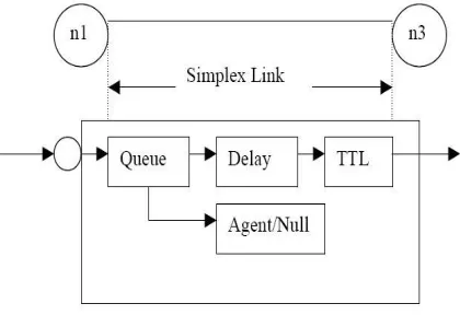
figure 2 link in ns2
figure 2 shows the construction of a simplex link in ns2. if a duplex-link is created, two simplex links will be created, one for each direction. in the link, packet is first enqueued at the queue. after this, it is either dropped, passed to the null agent and freed there, or dequeued and passed to the delay object which simulates the link delay. finally, the ttl (time to live) value is calculated and updated.
links can be created with the following command:
$ns duplex/simplex-link endpoint1 endpoint2 bandwidth delay queue-type
for example, to create a duplex-link with droptail queue management between n0 and n2: $ns duplex-link $n0 $n2 15mb 10ms droptail
creating a simplex-link with red queue management between n1 and n3:
$ns simplex-link $n1 $n3 10mb 5ms red
the values for bandwidth can be given as a pure number or by using qualifiers k (kilo), m (mega), b (bit) and b (byte). the delay can also be expressed in the same manner, by using m (milli) and u (mikro) as qualifiers. there are several queue management algorithms implemented in ns2, but in this exercise only droptail and red will be needed.
1.3.
tracing and monitoring
381
drops or number of arrived packets in the queue. the monitor can be used to collect these quantities for all packets or just for a specified flow (a flow monitor).
1.3.1.
traces
all events from the simulation can be recorded to a file with the following commands: settrace_all [open all.dat w]
$ns trace-all $trace_all
$ns flush-trace
close $trace_all
first, the output file is opened and a handle is attached to it. then the events are recorded to the file specified by the handle. finally, at the end of the simulation the trace buffer has to be flushed and the file has to be closed. this is usually done with a separate finish procedure. if links are created after these commands, additional objects for tracing (enqt, deqt, drpt and recvt) will be inserted into them.
figure 3 link in ns2 when tracing is enabled
these new objects will then write to a trace file whenever they receive a packet. the format of the trace file is following:
+ 1.84375 0 2 cbr 210 --- 0 0.0 3.1 225 610 - 1.84375 0 2 cbr 210 --- 0 0.0 3.1 225 610 r 1.84471 2 1 cbr 210 --- 1 3.0 1.0 195 600 r 1.84566 2 0 ack 40 --- 2 3.2 0.1 82 602
+ 1.84566 0 2 tcp 1000 --- 2 0.1 3.2 102 611 - 1.84566 0 2 tcp 1000 --- 2 0.1 3.2 102 611
+ : enqueue - : dequeue d : drop r : receive
the fields in the trace file are: type of the event, simulation time when the event occurred, source and destination nodes, packet type (protocol, action or traffic source), packet size, flags, flow id, source and destination addresses, sequence number and packet id. in addition to tracing all events of the simulation, it is also possible to create a trace object between a particular source and a destination with the command:
$ns create-trace <type><file><src><dest>
where the type can be, for instance,
enque – a packet arrival (for instance at a queue)
deque – a packet departure (for instance at a queue)
drop – packet drop
382
1.3.2.
monitors
with a queue monitor it is possible to track the statistics of arrivals, departures and drops in either bytes or packets. optionally the queue monitor can also keep an integral of the queue size over time.
for instance, if there is a link between nodes n0 and n1, the queue monitor can be set up as follows:
set qmon0 [$ns monitor-queue $n0 $n1]
the packet arrivals and byte drops can be tracked with the commands:
set parr [$qmon0 set parrivals_]
setbdrop [$qmon0 set bdrops_]
besides assigning a value to a variable the set command can also be used to get the value of a variable. for example here the set command is used to get the value of the variable “parrivals” defined in the queue monitor class.
a flow monitor is similar to the queue monitor but it keeps track of the statistics for a flow rather than for aggregated traffic. a classifier first determines which flow the packet belongs to and then passes the packet to the flow monitor.
theflowmonitor can be created and attached to a particular link with the commands:
setfmon [$ns makeflowmon fid]
$ns attach-fmon [$ns link $n1 $n3] $fmon
notice that since these commands are related to the creation of the flow-monitor, the commands are defined in the simulator class, not in the flowmonitor class. the variables and commands in the flowmonitor class can be used after the monitor is created and attached to a link. for instance, to dump the contents of the flowmonitor (all flows):
$fmon dump
if you want to track the statistics for a particular flow, a classifier must be defined so that it selects the flow based on its flow id, which could be for instance 1:
setfclassifier [$fmon classifier]
set flow [$fclassifier lookup auto 0 0 1]
1.4.
controlling the simulation
after the simulation topology is created, agents are configured etc., the start and stop of the simulation and other events have to be scheduled. the simulation can be started and stopped with the commands
$ns at $simtime “finish”
$ns run
the first command schedules the procedure finish at the end of the simulation, and the second command actually starts the simulation. the finish procedure has to be defined to flush the trace buffer, close the trace files and terminate the program with the exit routine. it can optionally start nam (a graphical network animator), post process information and plot this information.
the finish procedure has to contain at least the following elements:
proc finish {} {
global ns trace_all
$ns flush-trace
close $trace_all
exit 0
383
other events, such as the starting or stopping times of the clients can be scheduled in the following way:
$ns at 0.0 “cbr0 start”
$ns at 50.0 “ftp1start”
$ns at $simtime “cbr0 stop”
$ns at $simtime “ftp1 stop”
if you have defined your own procedures, you can also schedule the procedure to start for example every 5 seconds in the following way: proc example {} {
global ns
set interval 5
….
…
$ns at [expr $now + $interval] “example”
}
2.
simple simulation examplethis section presents a simple ns simulation script and explains what each line does. example 3 is an otcl script which creates the simple network configuration and runs the simulation scenario in figure 4. to run this simulation, copy the code in example 3 in a file named "ns-simple.tcl" and type "ns ns-"ns-simple.tcl" at shell prompt.
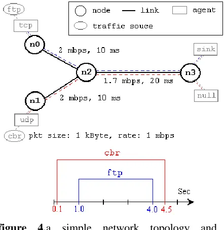
figure 4.a simple network topology and simulation scenario
the network consists of 4 nodes (n0, n1, n2, n3) as shown in above figure. the duplex links between n0 and n2, and n1 and n2 have 2 mbps of bandwidth and 10 ms of delay. the duplex link between n2 and n3 has 1.7 mbps of bandwidth and 20 ms of delay. each node uses a droptail queue, of which the maximum size is 10. a "tcp" agent is attached to n0, and a connection is established to a tcp "sink" agent attached to n3. as default, the maximum size of a packet that a "tcp" agent can generate is 1kbyte. atcp "sink" agent generates and sends ack packets to the sender (tcp agent) and frees the received packets. a "udp" agent that is attached to n1 is connected to a "null" agent attached to n3. a "null" agent just frees the packets received. a "ftp" and a "cbr" traffic generator are attached to "tcp" and "udp" agents respectively, and the "cbr" is configured to generate 1 kbyte packets at the rate of 1 mbps. the "cbr" is set to start at 0.1 sec and stop at 4.5 sec, and "ftp" is set to start at 1.0 sec and stop at 4.0 sec.
384
#define different colors for data flows (for nam)
$ns color 1 blue $ns color 2 red
#open the nam trace file set nf [open out.nam w] $ns namtrace-all $nf
#define a 'finish' procedure procfinish {} {
global ns nf $ns flush-trace
#close the nam trace file close $nf
#execute nam on the trace file exec namout.nam&
exit 0 }
#create four nodes set n0 [$ns node] set n1 [$ns node] set n2 [$ns node] set n3 [$ns node]
#create links between the nodes $ns duplex-link $n0 $n2 2mb 10ms droptail
$ns duplex-link $n1 $n2 2mb 10ms droptail
$ns duplex-link $n2 $n3 1.7mb 20ms droptail
#set queue size of link (n2-n3) to 10
$ns queue-limit $n2 $n3 10 #give node position (for nam) $ns duplex-link-op $n0 $n2 orient right-down
$ns duplex-link-op $n1 $n2 orient right-up
$ns duplex-link-op $n2 $n3 orient
right
#monitor the queue for link (n2-n3). (for nam)
$ns duplex-link-op $n2 $n3 queuepos 0.5
#setup a tcp connection set tcp [new agent/tcp] $tcp set class_ 2
$ns attach-agent $n0 $tcp set sink [new agent/tcpsink] $ns attach-agent $n3 $sink $ns connect $tcp $sink $tcp set fid_ 1
#setup a ftp over tcp connection set ftp [new application/ftp] $ftp attach-agent $tcp $ftp set type_ ftp
#setup a udp connection set udp [new agent/udp] $ns attach-agent $n1 $udp set null [new agent/null] $ns attach-agent $n3 $null $ns connect $udp $null $udp set fid_ 2
#setup a cbr over udp connection set cbr [new application/traffic/cbr] $cbr attach-agent $udp
$cbr set type_ cbr
$cbr set packet_size_ 1000 $cbr set rate_ 1mb
$cbr set random_ false
#schedule events for the cbr and ftp agents
385
$ns at 4.5 "$cbr stop"
#detach tcp and sink agents (not really necessary)
$ns at 4.5 "$ns detach-agent $n0 $tcp ; $ns detach-agent $n3 $sink"
#call the finish procedure after 5 seconds of simulation time
$ns at 5.0 "finish"
#print cbr packet size and interval puts "cbr packet size = [$cbr set packet_size_]"
puts "cbr interval = [$cbr set interval_]"
#run the simulation $ns run
example 3.a simple ns simulation script
the following is the explanation of the script above. in general, an ns script starts with making a simulator object instance.
setns [new simulator]: generates an ns simulator object instance, and assigns it to variable ns (italics is used for variables and values in this section). what this line does is the following:
o create a scheduler (default is calendar scheduler)
the "simulator" object has member functions that do the following:
o create compound objects such as nodes and links (described later)
o connect network component objects created (ex. attach-agent)
o set network component parameters (mostly for compound objects)
o create connections between agents (ex. make connection between a "tcp" and "sink")
o specify nam display options
o etc.
most of member functions are for simulation setup and scheduling, however some of them are for the nam display. the "simulator" object member function implementations are located in the "ns-2/tcl/lib/ns-lib.tcl" file.
$ns color fid color: is to set color of the packets for a flow specified by the flow id (fid). this is for the nam display, and has no effect on the actual simulation.
$nsnamtrace-all file-descriptor: it tells the simulator to record simulation traces in nam input format. it also gives the file name that the trace will be written to later by the command $ns flush-trace. similarly, the member function trace-all is for recording the simulation trace in a general format.
procfinish {}: is called after this simulation is over by the command $ns
at 5.0 "finish".in this function, post-simulation processes are specified.
setn0 [$ns node]: the member function node creates a node.
$ns duplex-link node1 node2 bandwidth delay queue-type: creates two simplex links of specified bandwidth and delay, and connects the two specified nodes. in ns, the output queue of a node is implemented as a part of a link, therefore users should specify the queue-type when creating links. in the above simulation script, droptail queue is used.
386
$ns duplex-link-op node1 node2 ...: the next couple of lines are used for the nam display. this line of code is used to monitor the queue for the link between the nodes node1 and node2. user can see the packets in the queue, and after a while the user can even see how the packets are being dropped.
now that the basic network setup is done, the next thing to do is to setup traffic agents such as tcp and udp, traffic sources such as ftp and cbr, and attach them to nodes and agents respectively.
settcp [new agent/tcp]: this line creates a tcp agent. to create agents or traffic sources, a user should know the class names these objects (agent/tcp, agnet/tcpsink, application/ftp and so on).
$ns attach-agent node agent: the attach-agent member function attaches an attach-agent object created to a node object. actually, this function calls the attach member function of specified node, which attaches the given agent to itself. therefore, a user can do the same thing by, for example, $n0 attach $tcp.
$ns connect agent1 agent2: after two agents that will communicate with each other are created, the next thing is to establish a logical network connection between them.
assuming that all the network configuration is done, the next thing to do is write a simulation scenario (i.e. simulation scheduling). thesimulator object has many scheduling member functions. however, the one that is mostly used is the following:
$ns at time "string": this member function of a simulator object makes the scheduler (scheduler_ is the variable that points the scheduler object created by
[new scheduler] command at the beginning of the script) to schedule the execution of the specified string at given simulation time. for example, $ns at 0.1 "$cbr start"will make the scheduler call a start member function of the cbr traffic source object, which starts the cbr to transmit data.
after all network configurations, scheduling and post-simulation procedure specifications are done, the only thing left is to run the simulation. this is done by $ns run.
3.
extending ns: creating a new agent387
XIII.
CONCLUSION:
The paper introduced a new concept of self-protocol trustiness (spt) in which detecting a malicious intruder is accomplished by complying with the normal protocol behavior and luring the malicious node to give an implicit avowal of its malicious behavior. we introduced a new blackhole resisting mechanism (brm) that can be incorporated into any reactive routing protocol in manet. the proposed mechanism did not use cryptographic techniques which conserves the power and computation resources. furthermore, the mechanism did not require any additional packets and hence does not incur any additional overhead. as an example, we incorporated the paper introduced a new concept of self-protocol trustiness (spt) in which detecting a malicious intruder is accomplished by complying with the normal protocol behavior and luring the malicious node to give an implicit avowal of its malicious behavior. we introduced a new blackhole resisting mechanism (brm) that can be incorporated into any reactive routing protocol in manet. the proposed mechanism did not use cryptographic techniques which conserves the power and computation resources. furthermore, the mechanism did not require any additional packets and hence does not incur any additional overhead. as an example, we incorporated our blackhole resisting mechanism into aodv to study the our blackhole resisting mechanism into aodv to study the
XIV.
REFERENCE:
[1] m. a. abdelshafy and p. j. king. analysis of security attacks on
aodv routing. in 8th international conference for internet technology
and secured transactions (icitst), pages 290–295, london, uk, dec
2013.
[ 2] m. a. abdelshafy and p. j. king. aodv&saodv under attack:
performance comparison. inadhoc-now 2014, lncs 8487,
pages 318–331, benidorm, spain, jun 2014. [3] a. boukerche, b. turgut, n. aydin, m. ahmad, l. b¨ol¨oni, and
d. turgut. routing protocols in ad hoc networks: a survey. computer
networks, 55(13):3032–3080, september 2011.[4] n. choudhary and l. tharani. preventing black hole attack in aodv
using timer-based detection mechanism. in international conference on
signal processing and communication engineering systems (spaces),
pages 1–4, jan 2015.
[5] p. joshi. security issues in routing protocols in manets at network
layer. procedia computer science, 3:954–960, 2011.
[6] a. kumar. security attacks in manet - a review. ijca proceedings on
national workshop-cum-conference on recent trends in mathematics
and computing 2011, rtmc(11), may 2012. [7] s. lee, b. han, and m. shin. robust routing in wireless ad hoc networks.
in international conference on parallel processing workshops,
pages 73–78, 2002.
[8] n. mistry, d. c. jinwala, and m. zaveri. improvingaodv protocol
againstblackhole attacks. in international multiconference of engineers
388
march 2010.
[9] the network simulator ns-2. http://www.isi.edu/nsnam/ns/.
[10] p. papadimitratos and z. j. haas. secure link state routing for mobile
ad hoc networks. in symposium on applications and the internet