Volume-6 Issue-1
International Journal of Intellectual Advancements
and Research in Engineering Computations
Fabrication of gripping jaws and optimizing the process parameter values
in upsetting machine
S. Gejendhiran
1, C.M.Thangavel
2, K.Venkatesh
2, S.Kaliful Rahman
2 1Assistant Professor,
2UG Students
Department of Mechanical Engineering, Nandha Engineering College, Erode-52,
Tamil Nadu, India.
1
[email protected],
2[email protected]
Abstract - Engine Valves is one of the important parts which are used in all Internal Combustion Engines. The manufacturing process involves metal shearing, upsetting, forging, heat treatment, machining and special process. Out of these, an Upsetting process is an excellent electrically assisted preforming process for the production of high-quality engine valves. In which the copper jaws plays a vital role and are used for gripping the solid bar. In a copper jaw, there is only two sides are grooved and it will be used only for certain frequency, after exceeds that frequency it leads to run out specifications and improper formation of a bulb. So the copper jaws should replace, it will increase the cost and time to replace the jaws. In order to reduce the cost and time, four sides grooved copper jaws are used. In the upsetter machine, due to inappropriate parameters combinations could result in major defects on the valve. Based on parameter conditions, the solid bar deforms into proper bulb shape without cracks or folds. In order to reduce the defects in upsetter machine, the process parameter values are optimized using Taguchi's experimental design method and also a present effect of individual parameters on performance is estimated by using ANOVA. Confirmation tests with optimal levels of upsetting parameters are conducted to validate the test results.
Index words - Copper Jaws, Upsetter, Optimization, Taguchi method, ANOVA.
I.
INTRODUCTIONIn the recent industrial world, there is a growing demand for the economic manufacturing process and more efficient to improve product quality, reduce production cost and increase productivity. In an Internal Combustion (I.C) engine, a valve is one of the main parts which are used for inlet and exhaust operations. The manufacturing of engine valve initially involves in upsetting and forging process.
In an electrical-upsetting the solid bar is placed between gripping jaw and anvil, a high electric current at low frequency is passed through a solid bar section which is limited by contact electrodes of different potential and heated due to high current density and contact resistance. It can keep the continuous grain flow, excellent mechanical property, and corrosion resistance because of the elaborate macrostructure on the valve face. The axial force applied by a hydraulic piston simultaneously causes a decrease in length on one side of the cut bar bringing about an increase in cross-sectional area at the other end of the bar, and forming a bulb. After the formation of a bulb in hot condition, it has to be forged. Hot forging is performed at high speed, it will form a smooth and blend head profile of engine valve.
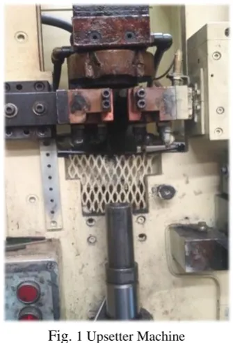
Fig.
1 Upsetter Machineand it will be used only for the certain frequency after exceeds that frequency it leads to the run out specifications and improper formation of a bulb shape. Due to the certain changing frequency, the cost of replacing the copper jaws gets high.
In an upsetting machine the important process parameters are, Electric current, Upsetting pressure, Clamping pressure, due to the inappropriate combination of these parameters, the formation of a bulb is improper and a bulb is not meet the required temperature for forging that leads to major rejections. In order to reduce the cost of replacing the copper jaws after exceeds that frequency, four sides grooved copper Jaws are used. In which the copper plates are used as a side plate.
To eliminate the impressions caused by the threaded bolts for tightening the jaws in upsetter machine and also to reduce the rejections in upsetter machine the process parameter values are optimized using Taguchi’s experimental design method and signal to noise (S/N) ratio are employed to find the optimal process parameter levels. A present effect of individual parameters on temperature is estimated by using ANOVA. Utilization of such techniques reduces iterative and time-consuming approach.In the present study, Taguchi method precisely optimized the control parameters on upsetter machine.
II.
LITERATURE SURVEY[1] Guo-zheng Quan et al. investigated on electric upsetting defects during formation process and optimizing the process parameter values. In the upsetting process, the main factor causing the defect is the large temperature decrease of the deformed portion after the formation of deformed shape in the preliminary stage of electric upsetting. In order to avoid the secondary upsetting defect successfully, an optimization method based on a closed-cycle control of current was established.
[2] J.Berube et al. provided a systematic study on the performance of SN ratio. Robust parameter design is one of the most creative and effective tools in quality engineering. Taguchi’s approach to parameter design with the use of the signal to noise ratio for variation reduction and parameters design optimization. The estimated SN ratios are analyzed to determine which control factors have an effect on the process. By the utilization of signal to noise ratio, the optimal levels are been identified and the process parameters are optimized.
[3] K.Elayaraja et al. investigated and developed a process quality control through the proportionate valve
in electrical upsetting. Based on the bulb temperature measured at the time of operation, the proportionate valve will vary the upset pressure to obtain the bulb without fold and crack. The controlling of upsetter during operation includes sensing of temperature and controlling it by varying the power intensity in the circuit through the upsetter pressure. The process parameter could not be controlled during the process that leads to folding and cracks. By using the proportionate valve used in the upsetting cylinder the cracks, folds and bulb shape modifications based on the valve profile can be reduced.
III.
GRIPPING JAWSIn an electrical upsetting machine, the gripping jaws plays a most important role to grip the solid bar under transverse clamping pressure and also it provides as a guideway towards anvil by the application of upset pressure. By self-resistance and contact resistance one portion of material has been heated and becomes plastic, the upsetting cylinder provides an adjustable axial pressure to compress the bar and enlarge it at the hot end and create a ball against the anvil.
The material used for the gripping jaw is copper as shown in Fig. 2. Due to excellent electrical and thermal conductivities copper and its alloys are widely used in a variety of products that enable and enhance good strength, formability and having outstanding resistance to corrosion, fatigue and they are generally non-magnetic.
Fig. 2 Two Sides Grooved Copper Jaws
Due to the two sides grooved in one jaw only two positions are changed, after the jaws get totally replaced. It will increase the cost and also consumes time to replace the jaws in upsetter machine. In order to reduce the cost and time to replace the copper jaws. An analysis is made to redesign the gripping jaws and the designs are modified based on the analysis.
IV.
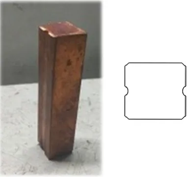
DESIGNING OF GRIPPING JAWThe two sides grooved copper jaw design are modified into four sides grooved jaw as shown in Fig. 3. By which the one side exceeds that frequency, position of jaw are changed to another side. In which all the four sides are utilized.
Fig. 3 Four Sides Grooved Copper Jaws
The dimensions of the copper jaw are 19×19×50 mm and the grooved radius is 3.25 mm. The sharp corners are removed by 0.5 × 450.
Fig. 4 Copper Plates
In the copper jaws, all the four sides are used, in which one side faces the threaded bolt for tightening the jaws in upsetter machine. To eliminate the impression on grooved sides, a copper plate is used as a side plate in Fig. 4. The copper plate has a thickness of 0.8 mm. Due to electrical conductivity, the copper is used as a material in which copper plate act as an electrical conductor.
By the implementation of four sides grooved copper jaw with side plate, the cost for copper jaws are lowered and also replacement time will be reduced.
V.
DEFECTS IN UPSETTING PROCESSGenerally, the preformed shape by electric upsetting should be controlled in a reasonable range, so as to ensure the forming quality of engine valves in final forming process. An inappropriate parameters combination in an electric upsetting process could result in unqualified shape or even lead to defects like external waviness and folding represented in Fig. 5.
(a) (b)
Fig. 5 (a) External Waviness, (b) folding.
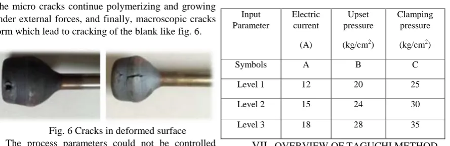
to stress concentration and initiation of micro cracks. The micro cracks continue polymerizing and growing under external forces, and finally, macroscopic cracks form which lead to cracking of the blank like fig. 6.
Fig. 6 Cracks in deformed surface The process parameters could not be controlled during the process that lead cracks or folds in the valves. The product quality is not stable and shape of the bulb cannot be changed in a single setting. In order to reduce the defects in electrical upsetting process, the process parameters are optimized by using Taguchi’s experimental design method.
However, processing parameters including Electric current, Clamping pressure, and Upsetting pressure are involved in electric upsetting process. Optimization of processing parameters to obtain satisfactory shape in electric upsetting process. The Taguchi method is used to formulate the experimental layout,
t
he response has been analyzed using S/N ratio, and ANOVA method is used to analysis the effect of input process parameters on the upsetting machine and founded the optimal parameters values.VI.
EXPERIMENTAL DETAILSThe experiments were conducted on upsetter machine as shown in Fig.1 which consist of anvil, copper jaws, upsetting cylinder, and electric supply system. The material used for the experiments are Martensite materials with steel grade SUH-11 and their dimensions are, length 182 mm and diameter 5.675. The machine has current settings from 10A to 20A, Lower current leads to cracks and improper formation of bulb and higher current leads to improper preformed shape. So the current is selected in the range of 12 - 18 A. An upset pressure settings from 15 to 45 kg/cm2, Lower upset pressure leads to increase in cycle time that will decrease productivity and the higher upset pressure which leads to the stem bending, So the upset pressure is selected in the range of 20 kg/cm2 - 28 kg/cm2. A Clamping pressure settings from 15 to 45 kg/cm2, Lower clamping pressure leads to the improper gripping of material and higher clamping pressure leads to worn of jaws life. So, the clamping pressure is taken in the range of 25kg/cm2 - 35 kg/cm2. The number of experiments and input levels are decided based on the design of experiments and the input parameters and their levels are presented in Table 1.
Table 1: Input Parameters Levels.
Input Parameter
Electric current
(A)
Upset pressure
(kg/cm2)
Clamping pressure
(kg/cm2)
Symbols A B C
Level 1 12 20 25
Level 2 15 24 30
Level 3 18 28 35
VII.
OVERVIEW OF TAGUCHI METHODTaguchi’s robust design method involves in reducing the variation in a process. To study the entire parameter space with only a small number of experiments the Taguchi method, uses a special design of Orthogonal Arrays (OA). By utilization of this method, it has greater advantage in conducting experiments, saving efforts, saving experimental time, reducing the cost and discovering significant factors quickly. It is a powerful tool for the design of a high-quality system. Taguchi uses the S/N ratio to measure the quality characteristic deviating from the desired value. Depending on the particular design problem, different S/N ratios are applicable, including “Higher is Better” (HB), “Lower is Better” (LB), “Nominal is Best” (NB).
Taguchi’s L9 orthogonal array is chosen to design the experiments and 9 tests are conducted to study the effect of various process parameters like discharging current, upsetting pressure, clamping pressure on the temperature are presented in Table 2.
As the objective is to obtain the high temperature, it is concerned with obtaining a larger value for temperature. Hence, the required quality characteristic for getting higher Temperature is larger the better, which states that the output must be as large as possible.
Table 2: L9 Orthogonal Array.
Expt. No.
FACTORS RESPONSE
S/N ratios A B C TEMPERATURE
1 1 1 1 982 59.84
2 1 2 2 1014 60.12
3 1 3 3 1043 60.37
4 2 1 2 1047 60.39
5 2 2 3 1064 60.53
6 2 3 1 1029 60.24
7 3 1 3 1014 60.12
8 3 2 1 1072 60.61
VIII.
ANALYSIS OF VARIENCEThe Analysis of Variance (ANOVA) is a common statistical technique to determine the percent contribution of each factor for results of the experiment. The ANOVA is used to calculate the parameters known as Degree of Freedom (DOF), sum of squares SS, variance and percentage of each factor. Further, the Fisher’s F-ratio, the ratio between the regression mean square and the mean square error, is used to identify the most significant factor on the performance characteristic.
The Fisher’s ratio is also called F value. The F test is used to find that the larger value for a particular parameter, the greater the effect on the performance characteristics due to the change in that parameter. The P-value reports the significance level (suitable and unsuitable). Percent (%) represents the significance rate of the upsetting parameters on the response.
IX.
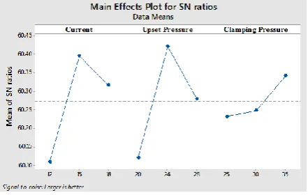
RESULTS AND DISCUSSIONThe main effect plot for S/N ratio, for Electric current, upset pressure, clamping pressure factor are plotted graphically as shown in Fig. 7.
Fig. 7 Main effect plot for S/N ratio
The graphical representation reveals that the combination (2, 2, 3) is the best combination for getting higher temperature. This corresponds to temperature at 15 A current, 24 kg/cm2 upsetting pressure with 35 kg/cm2 clamping pressure factor. The prediction is matching with the experimental trial.
For establishing the significance of each parameter, a response table for S/N ratio is constructed. The difference between the maximum and minimum is termed as Delta. The calculated value of delta for the different parameters are compared to find out the significance of each parameter. The response table for S/N ratio along with rank is shown in Table.3.
Table.3. Response Table for S/N Ratio
Level
Current
Upset
Clamping
Pressure
Pressure
1
60.11
60.12
60.23
2
60.4
60.42
60.25
3
60.32
60.28
60.34
Delta
0.29
0.3
0.11
Rank
2
1
3
It was earlier observed that the current, upsetting pressure and clamping pressure are crucial parameters for the process and its variation has a major impact on the temperature. From the response table, it can be concluded that, the upsetting pressure is the most significant parameter followed by current.
X.
CONCLUSIONIn an electrical upsetting machine the gripping jaws are used for gripping the material. The design of two side grooved copper jaw is modified into four side grooved copper jaw. By the design modification the cost and time to replace the jaw are effectively reduced.
In an electrical upsetting machine the main factor causing the defect is the large temperature decrease of the deformed portion after the formation of deformed shape in the preliminary stage of electric upsetting. In order to reduce the defects Taguchi’s experimental design method are used.
This study has discussed an application of the Taguchi method for investigating the effects of formation temperature on the electric current, upsetting pressure and clamping pressure values in the upsetter machine. From the analysis of the results in the upsetter machine process parameters using S/N ratio approach, Analysis of Variance (ANOVA) and Taguchi’s optimization method, the following can be concluded that the upsetting pressure is the most significant parameter followed by Electric current and clamping pressure.
The corresponding formation temperature at 15 A current, 24 kg/cm2 upsetting pressure with 35 kg/cm2 clamping pressure are obtained.
REFERENCES
[1] A.H.Mane, “Design and Analysis of Secondary Upsetter Die to Correct Under Filling Problem for Forged Front Axle Beam”, International
[2] Abdulkadir Yasar, Ali Keskin, Kerimcan celebi, “Numerical Analysis and Optimization of Engine Valves”, International Journal of Automotive
Engineering and Technologies, ISSN: 2146-9067, (1), 2017, pp. 19 – 25.
[3] Chandramouli S, Shrinivas Balraj U and Eswaraish K, “Optimization of electrical discharge machining process parameters using Taguchi method”, International Journal of
Advanced Mechanical Engineering. ISSN: 2250-3234, 2014, 4(4), pp. 425-434.
[4] Cristina Bunget, Wesley A. Salandro, Laine mears, John T.Roth, “Energy-Based Modeling of an Electrically-Assisted Forging Process”,
International Journal for Science and Engineering, 131(3), 2009.
[5] Guo-zheng Quan, Zhen-yu zou, Zhi-hua zhang, Jia Pan, “A study on formation of secondary upsetting defect in electric upsetting and optimization of processing parameters based on multi-field coupling FEM”, Materials Research,
2016, 19(4), pp.856-864.
[6] H.S.Jeong, J.R.Cho, N.K.Lee, H.C.Park, “Simulation of electric upsetting and forging process for large marine for diesel exhaust valves”, ISSN: 1662-9752, 2006, Vol. 510-511,
pp 142-145.
[7] J.Berube, C.F.Wu, “An Overview of Signal to Noise Ratio and Related Measures in Parameter Design Optimization”, An Indian Journal of
Statistics, 62(3), 2000, pp.417-432.
[8] K.Elayaraja, P.Periyasamy, “In process quality control through proportionate valve in electrical upsetting of engine valve”, Applied Mechanics
and Materials 2014, Vol. 592-594, pp. 2665-2670.
[9] Karan Soni, S.M. Bhatt, Ravi Dayatar, Kashyap Vyas, “Optimizing IC engine exhaust valve design using fine element analysis”, International Journal
of Modern Engineering Research (IJMER), ISSN: 2249–6645, 2015, 5(5), pp.55-59.
[10]P.Dadras, “A Semi-Empirical Solution to Upset Forging”, ASME Journal of Engineering for
Industry, 103(482), 1981, pp.45-51.
[11]Quan Guozheng, Luo Guichang and Wen Hairong, “Influence of Electric Upsetting Process Variables on Temperature Field evolution By
Multi Field Coupling Finite Element Analysis”,
International Journal Of Precision Engineering And Manufacturing, ISSN: 2005-4602, 2015, 16(7), pp. 1525-1531.
[12]V.Mallikarjuna, K.Rajesh, S.M.D.Jamaal Basha, “Process Implement in the Manufacturing of Engine Valve”, International Journal of Advanced
Engineering Research and Science (IJAERS), ISSN: 2456-1908, 3(10), 2016.
[13]Xi yang, Bulent Chavdar, Alan Vonseggern, Taylan Altan, “Prediction and reduction of cracking issue in precision forging of engine valve using Finite element method”, International
Journal of Mechanical and Mechatronics Engineering, 9(2), 2015.
[14]Xiangfang Fan, Jiang Ye and Wei Wu, “Forming process of inlet valve 85Cr18Mo2v by electrical upsetting forming”, Asia-Pacific Engineering and
Technology Conference (APETC), 2017, ISBN: 978-1-60595-443-1, pp.596-603.
[15]Yuvraj K Lavhale, Prof.Jeevan salunke, “overview of failure trend of inlet & exhaust valve”, International Journal of Mechanical
Engineering and Technology (IJMET), ISSN 0976 – 6359, 2014, pp.104-113.
[16]Zhang-xing men, Ya-xin Ma, Tai-wenyue, Rui-lin Liu and Yue Tang, “Influence of upsetting process parameters on continued electric upset heating by coupled electro-thermal-mechanical simulation”,