IJSRSET1841142 | Received : 12 January 2018 | Accepted : 29 January 2018 | January-February-2018 [(4) 1 : 610-618]
© 2018 IJSRSET | Volume 4 | Issue 1 | Print ISSN: 2395-1990 | Online ISSN : 2394-4099 Themed Section : Engineering and Technology
610
Harmonic Mitigation using D-STATCOM with Renewable
Energy Sources for improved Power Quality using Intelligent
Controller
Dr. N. Samba Siva Rao1, Mochi Lavanya Devi Bai2
1Professor Department of Electrical & Electronics Engineering, NRI Institute of Technology, Agiripalli, Andhra
Pradesh, India
2PG Scholar Department of Electrical & Electronics Engineering, NRI Institute of Technology, Agiripalli,
Andhra Pradesh, India
ABSTRACT
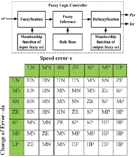
In this paper, distribution static compensator is used to compensate the source currents which are affected by the harmonics due to unbalanced and non-linear loads. Here a PV based inverter is used as a shunt active power filter to mitigate the current harmonics. The theory of unit vector control is used to generate the three phase reference currents. Hysteresis current controller (HCC) is used to generate the switching pulses for the gate drives of the grid interfacing inverter. The inverter act as a shunt active power filters to inject the compensated current to the system. The total harmonic distortion (THDs) of the source currents are reduced by using D-STATCOM. The THDs of the distribution system with and without are compared. Further the paper discuss about Fuzzy logic controller and impact of controller on power quality. By replacing PI with Fuzzy we can compare the THD of source current and observed that fuzzy is having better performance than PI. The whole work is been done in MATLAB/SIMULINK.
Keywords: Diesel Generator, D-STATCOM, MPPT, Power Quality, hysteresis current controller (HCC), total harmonic distortion (THD), Wind Generating System (WGS).
I.
INTRODUCTION
Renewable Energy Sources are those energy sources which are not destroyed when their energy is harnessed. Human use of renewable energy requires technologies that harness natural phenomena, such as sunlight, wind, waves, water flow, and biological processes such as anaerobic digestion, biological hydrogen production and geothermal heat. Amongst the above mentioned sources of energy there has been a lot of development in the technology for harnessing energy from the wind. Wind is the motion of air masses produced by the irregular heating of the earth’s surface by sun [1]. These differences consequently create forces that push air masses around for balancing the global temperature or, on a
much smaller scale, the temperature between land and sea or between mountains. Wind energy is not a constant source of energy [2].It varies continuously and gives energy in sudden bursts.
generator with variable speed and a conversion stage, which is studied in this paper.
Most of the more important international standards define power quality as the physical characteristics of the electrical supply provided under normal operating conditions that do not disrupt or disturb the customer’s processes. Therefore, a power quality problem exists if any voltage, current or frequency deviation results in a failure or in a bad operation of customer’s equipment. However, it is important to notice that the quality of power supply implies basically voltage quality and supply reliability. Voltage quality problems relate to any failure of equipment due to deviations of the line voltage from its nominal characteristics, and the supply reliability is characterized by its adequacy (ability to supply the load), security (ability to withstand sudden disturbances such as system faults) and availability (focusing especially on long interruptions) [4-5].
Power quality problems are common in most of commercial, industrial and utility networks. Natural phenomena, such as lightning are the most frequent cause of power quality problems. Switching phenomena resulting in oscillatory transients in the electrical supply, for example when capacitors are switched, also contribute substantially to power quality disturbances. Also, the connection of high power non-linear loads contributes to the generation of current and voltage harmonic components.
Between the different voltage disturbances that can be produced, the most significant and critical power quality problems are voltage sags due to the high economical losses that can be generated. Short term voltage drops (sags) can trip electrical drives or more sensitive equipment, leading to costly interruptions of production [6] .For all these reasons, from the consumer point of view, power quality issues will become an increasingly important factor to consider in order to satisfy good productivity. On the other hand, for the electrical supply industry, the quality of
factors for ensuring customer loyalty in this very competitive and deregulated market [7]. To address the needs of energy consumers trying to improve productivity through the reduction of power quality related process stoppages and energy suppliers trying to maximize operating profits while keeping customers satisfied with supply quality, innovative technology provides the key to cost-effective power quality enhancements solutions [8]. However, with the various power quality solutions available, the obvious question for a consumer or utility facing a particular power quality problem is which equipment provides the better solution [9].
II.
PRINCIPLE OF D-STATCOM
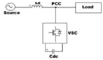
A D-STATCOM is a controlled reactive source, which includes a Voltage Source Converter and a DC link capacitor connected in shunt, capable of generating and/or absorbing reactive power. The operating principles of DSTATCOM are based on the exact equivalence of the conventional rotating synchronous compensator.
Figure 1.Circuit Diagram of D-STATCOM
VSC is equal to the AC terminal voltage, no reactive power is delivered to the system. If the output voltage is greater than the AC terminal voltage, the DSTATCOM is in the capacitive mode of operation and vice versa. The quantity of reactive power flow is proportional to the difference in the two voltages. For a DSTATCOM used for voltage regulation at the PCC, the compensation should be such that the supply currents should lead the supply voltages; whereas, for power factor Correction, the supply current should be in phase with the supply voltages. The control strategies studied in this paper are applied with a view to studying the performance of a D-STATCOM for power factor correction and harmonic mitigation.
III.
SYSTEM DESCRIPTION
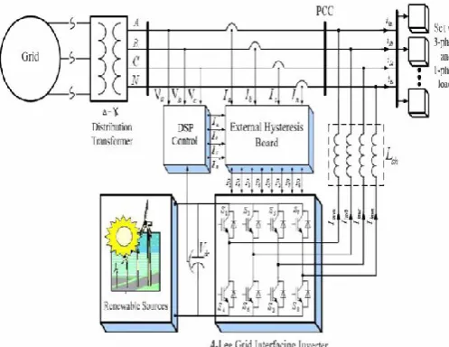
The above system consists of a photovoltaic cell as a RES connected to the dc-link of a grid interfacing inverter as shown in Figure 2. The voltage source inverter (VSI) interfaces the renewable energy source to the grid and delivers the generated power.
Figure 2. Schematic diagram of renewable based distribution system.
A. Photovoltaic Energy Panel
PV cell is an energy conversion device, which is used to convert the solar energy into an electrical energy and the amount of electrical energy produced depends upon solar irradiation and temperature.
B. Voltage Source Current Controlled Interfacing Inverter
A voltage source current inverter is a power electronic device which is connected in shunt with the system. The function of this inverter is to convert the dc voltage into a balanced three phase ac voltage. If the inverter output voltage is greater than the existing system voltage then the inverter acts in capacitive mode. The switching device used in this voltage source inverter is an IGBT.
C. Control Technique for Grid Interfacing Inverter as Shunt Active power filter
The turn ON and turn OFF instants of the inverter switches should be such that the load and the connected RES could be appeared as a balanced load to the system. For this type of control, we need to monitor the output of dc link capacitor continuously and is compared with the reference voltage Vdc*. The
difference between the reference and actual voltages will go through a voltage regulator, whose final output gives an active current component 1m. By multiplying this peak value (1m) with three unit sine vectors (Ua, Uh and Uc) which are in phase with the three source voltages will generate the reference current (la*, Ib* and Ic*). The reference grid neutral
current (In*) is set to zero being the instantaneous
sum of balanced grid currents. The synchronizing angle (9) obtained from phase locked loop (PLL) [I] is used to generate unity vector template as
(1)
(2)
Figure 3. Block diagram of grid interfacing inverter control.
The reference grid currents of the three phase system is given as
(4)
(5)
(6)
The neutral current is taken as
(7) The reference grid currents (la*, Ib* and Ic*) are
compared with actual grid currents (la, ,Ib and Ic) to
compute the current error as
(8)
(9)
(10)
D. Hysteresis Current Control
In this work, the hysteresis current control operation is used to control the operation of the VSI. The gate control signals for the grid interfacing inverter to act as a shunt active filter for compensating current harmonics is given by hysteresis current control signals.
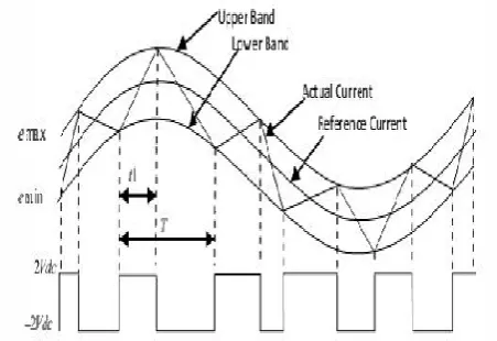
Figure 4. Waveform of Hysteresis Current Control.
An error signal laerr is used to control the switches in a
voltage source inverter. The difference between the desired current la' and the current being injected by the inverter la is taken as error. If the error exceeds the upper limit of the band, the upper switch of the inverter is turned OFF and the lower switch is turned ON, which implies that the current starts decreasing.
If the error crosses the lower limit of the band, the lower switch of the inverter is turned OFF and the upper switch is turned ON, which implies that the current starts increasing and gets back into the band. The upper and maximum values of the error signal are emin and emax respectively. The range of the error signal
is emax - emin directly controls the amount of ripple
content in the current output from VSI.
IV.
HYSTERESIS CURRENT CONTROL
forth (or bang-bang) switching of the upper and lower switches. The inverter then essentially becomes a current source with peak-to-peak current ripple, which is controlled within the hysteresis band, which makes the source current to be sinusoidal.
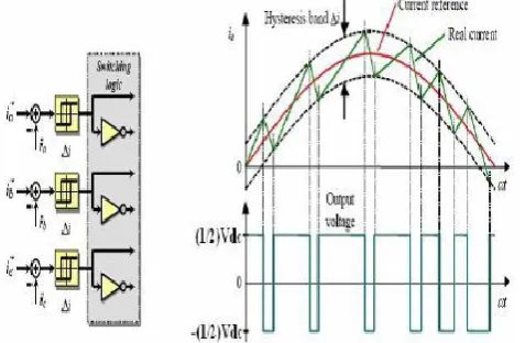
The switching logic is realized by three hysteresis controllers, one for each phase (figure.5). The hysteresis PWM current control, also known as “bang-bang “control, is done in the three phases separately. Each controller determines the switching -state of one inverter half-bridge in such a way that the corresponding current is maintained within a hysteresis band.
Figure 5. Hysteresis PWM Current Control and Switching Logic.
To increase a phase current, the affiliated phase to neutral voltage is equal to the half dc bus voltage until the upper band-range is reached. Then, the negative dc bus voltage -½Udc applied as long as the lower
limit is reached &c. More complicated hysteresis PWM current control techniques also exist in practice, e.g. adaptive hysteresis current vector control is based on controlling the current phasor in a α/β -reference frame. These modified techniques take care especially for the interaction of the three phases. Obviously, the dynamic performance of such an approach is excellent since the maximum voltage is applied until the current error is within predetermined boundaries (bang-bang control). Due to the elimination of an additional current controller, the motor parameter dependence is vastly reduced. However, there are some inherent drawbacks.
No fixed PWM frequency: The hysteresis controller generates involuntary lower sub harmonics.
•The current error is not strictly limited. The signal may leave the hysteresis band caused by the voltage of the other two phases.
•Usually, there is no interaction between the three phases: No strategy to generate zero-voltage phasors.
•Increased switching frequency (losses) especially at lower modulation or motor speed.
•Phase lag of the fundamental current (increasing with the frequency).
Hysteresis current control is used for operation at higher switching frequency, as this compensates for their inferior quality of modulation. The switching losses restrict its application to lower power levels. Due to the independence of motor parameters, hysteresis current control is often preferred for stepper motors and other variable-reluctance motors. A carrier-based modulation technique, as described in the next subsection, eliminates the basic shortcomings of the hysteresis PWM controller. However, when being compared to the hysteresis PWM, an additional current control loop, calculating the reference voltages, is required when subsequent modulation schemes are applied to high-performance motion control systems.
V.
WIND ENERGY BASED SYSTEM
generating electricity using renewable energy resources such as the wind are developed. Nowadays, the cost of wind power that is connected to the grid is as cheap as the cost of generating electricity using coal and oil. Thus, the increasing popularity of green electricity means the demand of electricity produced by using non renewable energy is also increased accordingly.
Figure 6. Structure of a typical wind energy system.
The major components of a typical wind energy conversion system include a wind turbine, generator, interconnection apparatus and control systems, as shown in Figure 6. Wind turbines can be classified into the vertical axis type and the horizontal axis type. Most modern wind turbines use a horizontal axis configuration with two or three blades, operating either down-wind or up-wind. A wind turbine can be designed for a constant speed or variable speed operation generator is coupled to the rotor of a wind turbine directly, offers high reliability, low maintenance, and possibly low cost for certain turbines , power electronic converters to provide a fixed frequency and fixed voltage power to their loads.
Fuzzy logic is widely used in machine control. The term "fuzzy" refers to the fact that the logic involved can deal with concepts that cannot be expressed as the "true" or "false" but rather as "partially true". Although alternative approaches such as genetic algorithms and neural networks can perform just as well as fuzzy logic in many cases, fuzzy logic has the advantage that the solution to the problem can be cast in terms that human operators can understand, so that
controller. This makes it easier to mechanize tasks that are already successfully performed by humans.
VI.
MATLAB/SIMULATION RESULTS
A. Balanced Nonlinear Load
Figure 7. Matlab/Simulink Model of balanced non-linear load.
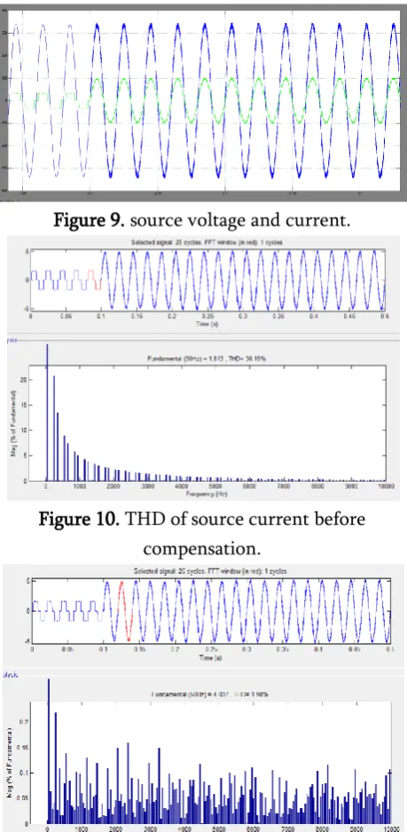
Figure 9. source voltage and current.
Figure 10. THD of source current before compensation.
Figure 11. THD of source current after compensation.
B. Unbalanced Non-linear Load
Figure 12. Matlab/Simulink Model of unbalanced non-linear load.
Figure 13. Simulation results of unbalanced Non-linear Load Source current, Load current, Inverter
current and source voltage.
Figure 14. source voltage and current.
Figure 15. THD of source current before compensation.
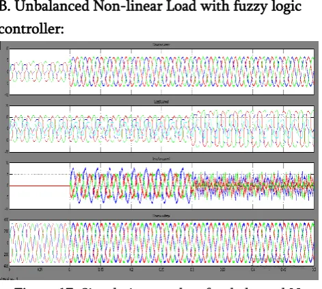
B. Unbalanced Non-linear Load with fuzzy logic controller:
Figure 17. Simulation results of unbalanced Non-linear Load Source current, Load current, Inverter
current and source voltage.
Figure 18. THD of source current after compensation using fuzzy controller
VII.
CONCLUSION
The D-STATCOM handled the situation without any difficulties and injected the appropriate voltage component to correct rapidly any changes in the supply voltage there by keeping the load voltage balanced and constant at the nominal value. The performance of a shunt active filter is studied by using multi-function grid interfacing inverter under various
load conditions. The power quality problems like current harmonics, current unbalance due to unbalanced and non linear load connected to the PCC is compensated effectively by using shunt active power filter (APF). The hysteresis current controller is used to generate the switching pulses for the gate drives of grid interfacing inverter. The proposed scheme is superior compared to the other conventional controller technique in terms of energy saving and dynamic performance. The PQ theory control with hysteresis loss current control algorithm based D-STATCOM has the ability for good compensation characteristics. By using this compensation strategy the THD (Total Harmonics Distortion) is reduced. Fuzzy logic controller gives better quality than conventional pi controller and THD is reduced.
VIII.
REFERENCES
[1]. K. Bala Nikilesh, P. Nageswara Rao' Harmonic Compensation using D-STATCOM in Combination with Renewable Energy Sources to
[2]. Enhance Power Quality' 978-1-4799-7678-2/15/$31.00 2015 IEEE
[3]. Mukhtiar Singh, Student Member, IEEE, Vinod Khadkikar, Member, IEEE, Ambrish Chandra, Senior Member, IEEE and Rajiv K. Varma, Senior Member, lEEE "Grid Interconnection of Renewable Energy Sources at the Distribution Level With Power-Quality Improvement Features."IEEE Transactions On Power
[4]. U. Borup, F. Blaabjerg, and P. N. Enjeti, "Sharing of nonlinear load in parallel-connected three-phase converters," IEEE Trans. Ind. Appl., vol. 37, no. 6, pp. 1817-1823, Nov.Dec. 2001. [5]. J. H. R. Enslin and P. J. M. Heskes, -Hannonic
interaction between a large number of distributed power inverters and the distribution network, l IEEE Trans. Power Electron., vol. 19, no. 6, pp. 1586-1593, Nov. 2004.
filter with renewable energy interface," presented at the Conf. IEEE Rnewable Energy & Power Quality, Seville, Spain, 2007.
[7]. J. M. Guerrero, L. G. de Vicuna, J. Matas, M. Castilla, and J. Miret, "A wireless controller to enhance dynamic perfonnance of parallel inverters in distributed generation systems," IEEE Trans. Power Electron., vol. 19, no. 5, pp. 1205-1213, Sep. 2004.
[8]. Karuppanan P ,Kamala KantaMahapatrab-PLL Synchronization With PID Controller Based on Shunt Active Power Line FILTER.I International Journal of Computer and Electrical Engineering,VoI.3,No.l,February 2011.
[9]. M. Aiello, A. Catalioti, S. Favuzza, G. Graditi, -Theoretical and Experimental Comparison of Total Harmonic Distortion Factors for the evaluation of Harmonic and Inter harmonic Pollution of Grid Connected."IEEE Transactions on Power Delivery, Vol. 21, No. 3, July 2006. [10]. I. M. A. Myrzik, and M. Calais, Member, IEEE