ON LINE TUNING OF INTELLEIGENT
CONTROLLER FOR INDUCTION
DRIVE SYSTEM
V.Jeyalakshmi, *
Head / EEE Department, PSN College of Engineering &Technology, Tirunelveli, Tamilnadu - 627152, India
e-mail: [email protected]
*Corresponding author S. Murugan,
Assistant Professor, Department of ICE,
Arulmigu Kalasalingam college of Engineering,Krishnankoil-626190 Srivilliputhur, TamilNadu, India. E-mail: [email protected] Abstract :
This paper presents Fuzzy Logic based gain tuning of proportional integral (PI) speed controller in an induction motor drive. Optimization considers the load and speed variations, and provides appropriate gains to the speed controller to obtain good dynamic performance of the motor. IM performance is checked with the optimal gains through the simulation studies in MATLAB/SIMULINK environment. Results are compared with hand tuning (fixed gains) and fuzzy logic (FL) speed controller. Hybrid of FL controller for the speed control of given motor is also performed to eliminate the drawbacks of PID controller like overshoot and undershoot and steady-state error. From the simulation studies, it is observed that FL controller produces better performance in terms of rise time, overshoot and settling time.
Keywords: Fuzzy logic, gain tuning, induction motor drives, optimization, speed controller.
1. Introduction
Through many years, electrical machines have been supplying industrial needs, and in many of these applications the speed control is a fundamental tool. Such applications in the past have been dominated by dc machines [6], however mechanical conversion from dc to ac and rotating contacts need constant maintenance, making its application more difficult. Such difficulties doesn’t exist in the induction motor, considered much simpler and robust as an assembling aspect, in general induction machines don’t have electrical contacts in moving parts between stator and rotor. However, because of its highly non-linear and coupled dynamic structure, an induction machine requires more complex control schemes. Traditional open-loop control of the induction machine with variable frequency may provide a satisfactory solution under limited conditions. However, when high performance dynamic operation is required, these methods are unsatisfactory. Therefore, more sophisticated control methods are needed to make the performance of the induction motor.
parameters and an increased and or decreased rotor resistance, self inductance and inertia. The proposed structure requires only input data to function, thus making it suitable for use with plants having model uncertainties such as electrical machines.
1.1 PI Controller For Induction Motor Drive
PI controllers are the feedback controller which makes the system less sensitive to changes in the surrounding environment and small changes in the system. They offer the simplest and yet most efficient solution too many real-world control problem [5]. These controllers are generally designed on the basis of linear control theory, even though the system is nonlinear in nature. It is a type of feedback controller whose output, that is a control variable (CV) is generally based on the error (e), between user defined set point (SP) and measured process variable (Y). Each element of the PI controller refers to the particular action taken on the error. It consists of two types of control such as Proportional and Integral control. Normally the parameters of these controllers are tuned either by the Empirical method (Z-N) or Analytical method (Root locus). There are several other methods are also used for tuning the PID controllers [2].
But this controller produces the response with more overshoot, more steady state error and more settling time with less accuracy. Hence it requires the proper tuning of the controller parameters to produce the control output according to the change in error with respect to time. To overcome the above difficulties, this paper proposes the fuzzy logic to tune the parameters of the PI controller [4]. When the controllers are tuned by fuzzy rules they can provide better performance even when the external disturbances occur.
2. IM drive system
Figure 1 shows the basic configuration of speed control of IM drive. The drive is controlled with two control loops, i.e. inner pulse width modulation (PWM) current control loop and outer speed control loop. Reference or command speed is compared with actual speed of the drive and speed error is processed through the speed controller. The output of the speed controller is torque command for the drive. The electrical torque of the drive is directly proportional to the q-axis current component (iqs) of the IM. Dividing the torque command by torque constant, the q-axis current command is obtained. Gain tuning of PI speed controller is performed by the Fuzzy logic technique.
Fig.1. Induction Motor Drive system
3. Mathematical model of 3 phase Induction motor
The state-space representation of the asynchronous motor depends on the choice of the reference frame and on the state variables selected for the electric equations. The choice of the state variable x depends on the objectives of the control or observation. For a complete model, the mechanical speed is a state variable. The outputs to be independently controlled are the norm of the rotor flux and the torque. The rotor flux norm needs to be controlled for system optimization. Once the torque is controlled, the speed and position can be controlled by simple outer linear loops, at least, if the load does not have significantly nonlinear dynamics.
Controller Inverter AC Drive
Speed Nact
As state variables, we choose the two components of stator currents, the two components of the rotor flux and the mechanical speed. As for the output y, the torque and the square of the rotor flux norm and for the input voltage, the stator voltage input u is selected. We can then write the model equations in the reference frame (d, q) as follows:
X
C
Y
BU
AX
X
.
.
(1)where
X
I
qI
d
q
d
T m r r r r m r r m r r l r l r s l r m r r l r S L R R L R R L L R L L R R L L L R L R R A 0 0 0 0 ; 0 0 0 0 0 0 0 1 1 L L
B ;
d qV
V
U
;C = [ 1 0 0 0] 3.1 Induction Motor parameters Torque constant - 4.1Nm/A Phase Stator resistance - 0.087 Ω
Phase rotor resistance - 0.228 Ω
Phase inductance - 35.5 mH Mutual inductance - 34.7mH Number of poles - 4
Moment of inertia - 0.305 kgm2 Rated speed - 314 rad/s (electrical) 4. Fuzzy Logic Controller
The main preference of the fuzzy-logic is that is easy to implement and that it has the ability of generalization. The basic configuration of the fuzzy-logic system is shown in Fig.2
Fig.2. Fuzzy Logic System
Fuzzy controllers are based on four well known stages. The fuzzification stage takes crisp numerical values and determines their degree of membership in each collection of sets which are given linguistic labels that are meaningful in terms of the problem to be solved. The second part is the fuzzy rule base which expresses relations between the input fuzzy sets A and B and the output fuzzy sets C in the form of: ‘ IF A and B THEN C’. The fuzzified inputs are combined using these rules in the third part, the fuzzy inference engine. This produces a combined fuzzy output set. The final part, the defuzzifier produces a crisp output from the combined fuzzy output set. Inputs and the output are non-fuzzy values. In this work, a simple Proportional-Derivative (PD) speed control scheme was implemented and used to assess the basic performance of the system. The output of the fuzzy controller uf(k) is given by:
Where Ff is a non linear function determined by fuzzy parameters, e(k), Ce(k) are the error and change-of-error
respectively.
A type of those controllers is fuzzy PD controller whose input is the error
e(k) = ωr (k) - ω(k) (3)
where ωr (k) is the output signal of the reference model and ω(k) is the process output at time k. The control goal is that the plant output signal ω(k) follows as closely as possible the output signal ωr(k) of the reference model. The reference model of the plant is an ideal model that has the desired characteristics related to the rise-time, steady-state error. The input-output dynamics of the reference model were assumed to be given by the following second-order model :
ωr (k+1) = a1 ωr(k) + a2 ωr(k-1) + r(k) (4)
The constant coefficient in the equation (14) were chosen to guarantee bounded-input bounded-output stability and the steady-state reference track is dictated by the amplitude and functional form of the input r(k) to the reference model. For the proposed fuzzy controller, the universe of discourse is first partitioned into the seven linguistic variables NB, NS ,NM, ZE, PS, PM, PB triangular membership functions are chosen to represent the linguistic variables. Fig.3 shows the membership functions and the fuzzy rules are illustrated in Table.1.
Fig. 3. Membership functions of (e, ∆e and ∆Iref)
Table1. Rule base
e
e
f
K
K
K
e
e
f
K
K
K
I I I
P P P
,
,
2 1
(5)
It is to he noted that KI and Kp are limited when the steady state is reached and initialized when the speed command change occurs, in order to avoid making at tasks the viability, and to ensure the global stability of the drive. From the inference rules table, it can be seen that the integral gain K, is more and more Increased for large positive or negative speed error e, and, more and more decreased for large positive or negative speed error variation ∆e. This will improve the speed rise time; but can lead to speed response with overshoot. The inference rules table shows that the proportional gain Kp is more and more increased for large positive or negative speed error variation ∆e, in the case of small positive or negative speed error e. The reasoning behind this is to avoid speed overshoots, and steady state errors
5 Simulation Results
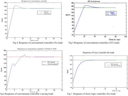
The performances of the proposed controllers are evaluated under a variety of operating conditions. The controller algorithm is housed inside the personal computer with Pentium-IV microprocessor and all numerical values of the simulation model are obtained either by measurements or identification from laboratory experiments. The software environment used for these simulation experiments is Matlab Ver. 6.5, with Simulink package. Many simulation tests were performed in order to compare the performances of the self-tuning PI speed controller of field oriented induction motor drive, to those obtained with a conventional PI controller. The speed behavior for different operating conditions such as response to step speed command from stand still, step load torque application and speed reversion transient, with nominal parameters and an increased and/or decreased rotor resistance, self inductance and inertia, is presented. Figure (4)shows speed response to No load torque condition from standstill for nominal operating conditions. Figure (5) shows speed response, when 25% of full load torque is applied from standstill for nominal operating conditions. Figure (6) shows speed response with a sudden rated load torque application between 3s and 6s and also between 11s to 12s. From the simulation result, we conclude that the conventional controller will not provide better speed control under disturbance condition.
Fig 4. Response of conventional controller (No load) Fig.5.Response of conventional controller (25% load)
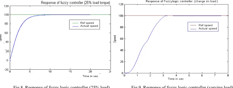
Fig.8. Response of fuzzy logic controller (25% load) Fig.9. Response of fuzzy logic controller (varying load)
From the simulation result we observe that, the fuzzy self tuning PI controller will provide constant speed even though under sudden change in load condition. As compared to classical PI controller this will provide better performance during transient conditions also.
5.1 Comparison Table:
A comparison that was made between Conventional and Fuzzy logic controller and the steady state characteristics are listed below:
Table 2. Comparison of steady state characteristics
6. Conclusion:
Nowadays the industry is rapidly changing its plants due the enormous technological development. Considering that has been a huge interest in safer control operation, this fuzzy logic model when applied tosuch systems presented satisfactory results. An another advantage that can be mentioned here is the fact that using fuzzy control is not necessary to change the control parameters as the reference speed changes, however with the classical PI controller this does not happens. With results obtained from digital simulation, it is clear that for the same operation condition the induction motor speed control using fuzzy logic technique had better performance than the PI controller, mainly when the motor was working at lower speeds.
For practical implementation, the values of PI gains obtained from Fuzzy logic at different speed and torque commands can be stored in the memory of a digital signal processor and used to operate the motor with optimal gains according to desired speed and torque. Unlike conventional fixed gain PI controller, tuning of PI gains using Fuzzy Logic is insensitive to step change of speed command and is preferred for the normal operation of the drive. Furthermore, online tuning is highly recommended to maintain good stability of the drive during parameter variations in the motor and in the controllers of the drive.
7. References
[1] Betin. F,Depernet.D, loczek. P, aqir.A,Pinchon.D and Goeldel.C, “Control of induction machine drive using fuzzy logic approach” IEEE Proceedings on Industrial Electronics,pp.361-366, 2002
[2] Berenji and P.Khedkar, "Learning and tuning fuzzy logic controllers through reinforcements." IEEE Trans. Neural Networks, vol. 3, No.3, pp.724-740,1996.
[3] Bose B.K, Power Electronics and AC Drives. Englewood Cliffs, NJ: Prentice Hall, 1986.
[4] Ho-Seok Lee, Taeck-Kie Lee, Soon-Bong Cho, Dong-Seok Hyun , “Speed control of induction motor using fuzzy algorithm with hierarchial structure ”-IEEE proceedings on intelligent control, pp.551-554,1993
[6] Radha Thangaraj,, Thanga Raj Chelliah1, Millie Pant1, Ajith Abrahamand Crina Grosan, “Optimal gain tuning of PI speed controller in induction motor drives using particle swarm optimization” Logic Journal of IGPL Advance Access published July 8, 2010 [7] Salerno C.H,T. LeFio, R.A.Araujo , “A fuzzy speed control for a three-phase induction motor” IEEE Porto Power Tech Conference
10-13th September, Porto Portugal,2001
[8] Sousa G. C. D and B. K. Bose, “A fuzzy set theory based control of a phase controlled converter dc machine drive,” IEEW Industrial Application Society Annual Meeting Con Rec., pp. 854-861, 1991.
[9] R.Toufouti S.Meziane ,H. Benalla, “Direct Torque Control for Induction Motor Using Fuzzy Logic” ACSE Journal, Volume (6), Issue (2), pp. 19-26, June, 2006.
[10] Qing-Guo Wang, , Tong-Heng Lee,Ho-Wang Fung, Qiang Bi, and Yu Zhang, “PID Tuning for Improved Performance” IEEE Transactions on Control Systems Technology, Vol. 7, no. 4, pp.457-463, 1999
V.Jeyalakshmi received his M.E. in Control and Instrumentation Engineering from Anna Univeraity, Chennai in 2006. She is currently working as an Assistant Professor and Head, Department of Electrical and Electronics Engg, PSN College of Engineering and Technology ,Tirunelveli, Tamilnadu. Her current research interests include Control system, Instrumentation , Power system and Genetic Algorithm.