www.nat-hazards-earth-syst-sci.net/10/1781/2010/ doi:10.5194/nhess-10-1781-2010
© Author(s) 2010. CC Attribution 3.0 License.
and Earth
System Sciences
Parametric studies and quantitative assessment of the vulnerability
of a RC frame building exposed to differential settlements
C. Negulescu and E. Foerster
BRGM, RNSC/RIS – French Geological Survey, 3 Avenue Claude Guillemin, 45060 Orl´eans cedex 2, France Received: 17 March 2008 – Revised: 3 March 2010 – Accepted: 14 July 2010 – Published: 1 September 2010
Abstract. The aim of this paper is to propose a simpli-fied methodology to evaluate the mechanical performances of buildings exposed to landslide hazard, by using proce-dures inspired from the seismic risk analysis, such as the Ca-pacity Spectrum Method (ATC 40, 1996). Landslide hazard involves so many aspects, that quantitative vulnerability as-sessment requires to consider one basic scenario at a time, i.e. one typology for the landslide hazard and one for the structural element considered. In this paper, we propose to assess vulnerability for simple one bay-one storey reinforced concrete (RC) frame structures subjected to differential set-tlements, using 2-D parametric nonlinear static time-history analyses. After a short review of methods used in practice to estimate building deformations induced by ground move-ments (e.g. differential settlemove-ments), we present the paramet-ric studies carried out to identify the most relevant parame-ters, in order to predict the structural damage, as well as the methodology to develop analytical fragility curves, that can be used to quantitatively evaluate the structural vulnerabi-lity in landslide risk analyses. Different types of parameters that could influence structural behaviour have been examined in this analysis: foundation type (i.e. different combinations of links), cross-section geometry, section reinforcement de-gree, displacement magnitudes and displacement inclination angles. We show that the magnitude and inclination angle of displacements can be used as two relevant parameters for this type of landslide scenario. Based on these results, some simulations are conducted using the software SeismoStruct (SeismoSoft, 2003), and the proposed structural damage lev-els consider the local strain limits of steel and concrete con-stitutive materials. Some preliminary fragility curves are pro-posed with respect to the magnitude of differential ground displacement. It can be seen that the curves
correspond-Correspondence to: C. Negulescu ([email protected])
ing to limit states LS2 (moderate damage) and LS4 (com-plete damage) in the present study, correspond respectively to the “tolerable settlements” “observed intolerable settle-ments” curves proposed by Zhang and Ng (2005).
1 Introduction
Landslide risk analysis is inherently complex. The greater difficulties in achieving reliable results for landslides in com-parison to other natural threats, such as earthquake or floods, as highlighted in literature, are due to the complexity in mod-elling landslide hazard, in identifying relevant intensity pa-rameters and in assessing vulnerability in a quantitative man-ner. According to many authors (e.g. Glade, 2003; Douglas, 2007), several prominent factors contribute to complexity in the case of landslides and some of the reasons explaining the scarcity of vulnerability studies are listed below:
1. the lack of accurate observational data necessary for re-liable hazard analysis: only events that caused substan-tial damages have been recorded and accurate informa-tion on the type, characteristics and damages due to the failure are often missing (quantification of a landslide intensity, damage analysis of structures, etc.);
2. the different time and geographical scales involved; 3. the temporal variations of the environment factors
(especially just after a landslide);
1782 C. Negulescu and E. Foerster: Vulnerability assessment of RC frame to settlements at risk for qualitatively similar landslide mechanism,
the wide range of processes and possible characteristics (e.g. size, shape, velocity, momentum) and the numer-ous categories of damages.
Generally speaking the risk is the convolution between the hazard and the vulnerability of the exposed elements. The same hazard could cause different damages if the structure is in masonry or in RC or if the foundation system is shal-low or deep. “Although the state of the art for identifying the elements at risk and their characteristics is relatively well de-veloped, the state of the art for assessment of vulnerability is in general relatively primitive” (IUGS, 1997). Yet, whatever the reasons and the difficulties, the quantitative assessment of vulnerability to landslides should be improved, by following for instance the advances made in earthquake risk assessment (Douglas, 2007).
In the next sections, we will first make a short review of the main methodologies used in practice, to assess damages to buildings subjected to ground movements. Then, we will present the model parameters and numerical schemes used for analysis in this paper. Results of the parametric studies carried out, in order to identify the parameters most relevant for prediction of the structural damage, are also discussed. Then, we present the methodology adopted to build analyti-cal fragility curves, which express the probability of reach-ing a given damage state of the structure for a given intensity of hazard (e.g. differential displacements in our case). When comparing the proposed fragility curves with some empirical curves existing in literature for the same typology of ground movements, we see that a good agreement is reached. How-ever, the proposed curves will have to be further validated on more observation date, in order to be used for quanti-tative assessment of the structural vulnerability in landslide risk analyses.
2 Review of methodologies to assess damages due to ground movements
Regarding methods to predict building damages due to foun-dation movements and settlements, classifications and com-parison prove to be a difficult task, as a large number of crite-ria can be used and there is no unified terminology describing the types of movements and the deformations experienced by the foundation.
Classifications can be done using either by the building typologies (masonry, RC frame, RC wall) or the associated modelling methods (simplified approach, detailed model, etc.). We may distinguished three categories of methods:
– Empirical methods (e.g. Skempton and MacDonald, 1956; Polshin and Tokar, 1957; Sowers, 1962; Bjerrum, 1963; R¨usch and Mayer, 1964; Beeby and Miles, 1969), which aim at establishing criteria of serviceability by relating the deformation observed from field surveys to the damage.
– Methods using structural engineering principles (Bur-land and Wroth, 1974; Boscardin and Cording, 1989; Boone, 1996; Finno et al., 2005; Bird et al., 2005a,b). – Methods based on numerical modelling (e.g. see Burd
et al., 2000).
Skempton and MacDonald (1956) and Polshin and Tokar (1957) were the first to derive recommendations on allowable settlements of structures based on empirical methods.
Recommendations from Skempton and MacDon-ald (1956) are obtained by treating data collected from settlements and damage observations on 98 buildings from which 40 showed signs of damages. The damage criterion that they used is the “angular distortion” defined as the ratio of the differential settlements and the distance between two points after eliminating the influence of the tilt of the building. Based on their observations, they reported a range of limit values depending on the type of building or foundation, to determine the magnitude of differential foundation movement that will cause cosmetic, i.e. archi-tectural damage to structures, or more seriously, structural damage. For instance, they propose a limit value of 1/300 for “angular distortion” corresponding to a threshold for crack initiation in walls and finishes. They note also that a value greater than 1/150 would cause structural damage. These recommendations have proved to be in reasonable agreement with further studies (Burland and Worth, 1974), especially for frame buildings.
Polshin and Tokar (1957) recognise different modes of de-formation for different types of buildings, so that they treat separately unreinforced load bearing walls and frame struc-tures. They define some limit criteria which depend on the “slope” (difference of settlement of two adjacent supports relative to the distance between them), the “relative deflec-tion” (ratio of deflection to the deflected part length) and the average settlement under the building. These criteria are in concordance with the values proposed by Skempton and Mc-Donald (1956) and are also in agreement with the results ob-tained later by Burland and Worth (1974).
Generally, empirical methods refer to the damage induced by settlements due to the own weight of the structure. De-spite the uncertainties related to all of these methods, guid-ance for tolerable movements are based on observations of building movements and the resulting damages. Limit values proposed by Polshin and Tolkar (1957) have been incorpo-rated into the 1955 Building Code of the URSS.
As for methods based on structural engineering princi-ples, the most emblematic and wildly used literature study on settlement-induced damage is the one published by Burland and Wroth in 1974. In their paper, they analyze the damage due to the foundation movement, as well as the interaction between the structure and the underlying ground.
by an equivalent uniform, weightless, elastic beam of length
L, heightH, and unit thickness (the Deep Beam Method, see Fig. 1). Then, they define a criterion for initial cracking based on the calculation of tensile strains developing in the beam. In order to assess the factors related to soil-structure interactions, they first evaluate the ground settlements at an equivalent site with no overlying building (so called ‘green-field’ settlements) and setting lateral strains to zero. Then, they impose the obtained displacements on a structural model of the building in order to assess the expected damage. This approach is interesting as it relies on sound theoretical back-grounds for damage induced by ground movements, which was new with regards to the previous works based on empir-ical observations only. However, a main issue concerns the difficulty to provide guidance on the selection of the equiva-lent beam features (e.g. equivaequiva-lent rigidity), especially when dealing with a multi-story structure.
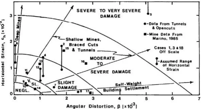
Boscardin and Cording (1989) have complemented Bur-land and Wroth’s concepts by including the effect of hor-izontal strain developing in the ground due to settlements. They note that this effect depends on the lateral stiffness of the structure. For instance, a frame structure would be more affected by horizontal ground strains than a structure with re-inforced concrete walls supported by continuous footings or with stiff floor systems. Based on the results of their stud-ies, they define categories of damage by developing relation-ships between the horizontal strain and the angular distortion (Fig. 2).
Boone (1996) proposes a Strain Superposition Method (SSM) that uses both equations of fundamental geometry and engineering principles, in order to assess damage to the con-structions. The SSM assesses the building damage by taking into consideration ground deformation patterns, damage cat-egory criteria and strain concept, but its complexity requires careful calculations and delicate definition of the problem conditions. The results obtained using the data from over 100 case histories of damaged building treated with Boone’s approach, are in reasonable agreements with those obtained by Boscardin and Cording’s approach.
The approach proposed by Bird et al. (2005a,b), uses an-alytical solutions to assess the expected damage of existing RC frame buildings due to liquefaction-induced differential ground movements. It proposes equations in order to rep-resent the deformational capacity of the critical column, by applying principles of displacement-based assessment, semi-empirical and semi-mechanical approaches, while the col-umn deformational demand related to ground motions is de-rived geometrically. In this approach, the structure deforma-tion is idealized in four cases considering differential vertical settlements and lateral movement associated with horizontal and vertical components. A first limit state is defined us-ing concrete and steel yield strains and geometrical proper-ties of the section. The authors propose also a second and a third limit state, each one depending on the admissible strain values for both materials separately. Only bare reinforced
Fig. 1. Illustration of the equivalent Deep Beam Method, used to replace an actual building by a uniform, weightless, elastic beam of unit thickness (Burland and Wroth, 1974).
concrete frame buildings are considered in this approach and the foundation deformation is assumed to be equal to the free-field deformation. Interesting conclusions arise from the results of this study regarding the damage mechanisms due to ground failure and the displacement demand of the floor columns. One important one concerns RC frame structures, for which the displacement demand is concentrated to the ground floor columns, as the upper stories generally rotate as a rigid body. Also, the authors show that for a single-bay case, deformations take place in the column rather than in the beam.
1784 C. Negulescu and E. Foerster: Vulnerability assessment of RC frame to settlements
Fig. 2. Interaction diagram relating angular distortion and horizontal strain for different categories of damage (Boscardin and Cording, 1989).
to using more sophisticated methods, such as finite elements (FE), etc., in order to estimate settlement-induced damages.
Two trends can be observed in FE calculations:
– uncoupled analysis, in which the soil and the structure are studied separately, and the soil settlements profile is imposed to the FE model of the building;
– coupled analysis, in which soil-structure interactions (SSI) are modelled.
Interesting conclusions have been reached from FE calcula-tions with SSI (e.g. Burd et al., 2000):
1. the weight of the building tends to increase the general magnitude of the settlements that develop underneath; 2. the stiffness of the building may act to reduce
differen-tial settlements;
3. depending on the building deformation mode (e.g. sag-ging or hogsag-ging), SSI effects may be more or less im-portant, as lateral restraint provided by the ground may reduce the extent of tensile stresses in the building; 4. SSI modelling generally leads to reduced differential
settlements for the building.
Contrary to SSI analyses, uncoupled analyses ignore the ef-fects of the building weight and stiffness on the ground set-tlement profile, which can lead to inaccurate prediction of expected settlements. However, SSI analyses may often be too complex and time consuming for practical vulnerability assessment over wide areas (e.g. urban settlements).
In the present paper, we propose a methodology based on 2-D uncoupled FE analyses, adapted from the standard seis-mic analysis, and that can be performed for vulnerability as-sessment of RC frame buildings subjected to differential
set-tlements. In next sections, we first describe the model param-eters and numerical schemes considered for analysis. Then, we present the parametric study carried out to identify the most relevant parameters, in order to predict the structural damage, as well as the methodology to develop analytical fragility curves, that can be used to quantitatively evaluate the structural vulnerability in landslide risk analyses.
3 Description of the case study
In order to identify some response parameters that govern the behaviour of the structure (a RC frame in our case) subjected to differential settlements, as well as to assess the settlement-induced damage of buildings, the proposed methodology has consisted in using 2-D parametric nonlinear static time-history uncoupled analyses. The main idea was to adapt the standard push-over analysis performed in seismic vulnerabi-lity assessment, which consists in setting a lateral force on a building. In the present paper, we have chosen to perform a “pull-down” analysis by imposing a static time-history dis-placement at one of the RC frame supports. Thus, the con-sidered input aggression, which increases linearly up to an imposed value, is a displacement applied in the frame plane (bottom of one column).
3.1 RC frame model
The studied structure is a simple 2-D one bay-one storey cast in-place RC frame, 4 m long (bay) and 3 m high (floor). We assume a uniform section for beams and columns (e.g.
H= 0.4 byW= 0.4 m).
Bird and co-workers (Bird et al., 2005b) show that the dis-placement demand is concentrated in the ground floor umn (if the imposed displacement concerns a marginal col-umn), and that the vertical deformation in level ground be-neath a single-bayed frame, places the same deformational demand on the members as in a multi-bayed frame.
Selected material properties are the following: 1. Steel:
(a) Yield strength (fy): 400 MPa. (b) Young modulus: 200 GPa. 2. Concrete:
(a) Compressive strength (fc): 21 MPa. (b) Strain at maximum strength: 0:002.
A bilinear stress-strain model with kinematic strain harden-ing of 0.5% has been used for reinforcement. The in-fills have not been considered here.
The section reinforcement degree considered for analy-sis is 0.7%. For concrete materials, a uni-axial nonlinear constant confinement model was used, assuming a constant confining pressure throughout the entire stress-strain range (Mander et al., 1988).
3.2 Numerical modelling scheme of structural elements The response of RC elements to static or dynamic loads is usually modelled either by the global response models (GRM), fibre models or FE models.
GRM are based on global hysteretic rules usually defined in force-displacement or moment-curvature relations. These models were intensively used until the development of alter-native techniques, such as fibre models. GRM are very effi-cient and can simulate the response of elements subjected to the combined effect of axial load and uni-axial bending (e.g. beams and columns in 2-D analyses). It becomes extremely difficult to model the effect of bi-axial bending with axial loads, because the hysteretic rules are extremely difficult to define, especially under cyclic and alternating loading.
The 3-D finite element models are not widely used for analysis because there still present several disadvantages re-lated to the complexity of the formulation and computational requirements. Most of the applications refer to the study of local behaviour of structures (e.g. isolated elements and con-nections).
Currently, fibre models are the most used modelling tech-nique in earthquake engineering, allowing accurate results with computational efficiency. These models have been ap-plied to a great variety of structures (buildings and bridges). However, as they are formulated at cross section level, it is not possible to simulate directly the effect of shear forces, the effect of concrete-steel bond failure and the deformability of joints. As a consequence, fibre models are efficient for ele-ments where flexure is predominant and should not be used for elements under high shear (Combescure, 2001).
Since the behaviour of frames subjected to column fail-ure is accompanied by significant cracking and deformation, only nonlinear models are suitable for structural analysis. In order to estimate the structural damage distribution along the member length and across the section area of the structure, the fibre model approach has been preferred in this study.
The sectional stress-strain state of beam-column elements is obtained through the integration of the nonlinear uni-axial stress-strain response of the individual fibres in which the section has been subdivided.
The spread of inelasticity along member length then comes as a product of the inelastic cubic formulation on which Seis-moStruct’s beam-column elements are based. A two-point Gaussian quadrature is used for numerical integration of the governing equations. If a sufficient number of elements is used (5–6 per structural member) the plastic hinge length of structural members subjected to high levels of material in-elasticity can be accurately estimated. More numerical de-tails can be found in SeismoSoft (2003). For the present analysis, the frame sections were divided into 200 fibres and the structural members, into 4 elements.
4 Description of the parametric studies
Several characteristics of the model were modified in order to i) evaluate their importance in the structural response and ii) attempt to provide classification criteria for them. Differ-ent types of parameters that could influence structural be-haviour have been considered in this analysis: foundation type (e.g. different links), cross-section geometry, reinforce-ment degree, displacereinforce-ment magnitudes and displacereinforce-ment in-clination angles. Each of these parameters varies in a range of reasonable values, while the other characteristics are kept fixed.
For example, if keeping fixed concrete dimensions and changing the reinforcement bar diameters, the reinforcement degree of the section varies between 0.5 and 1%. These rein-forcement percentages represent poorly confined buildings, which is the case for a large majority of existing one bay-one story RC frames. The analysed structure characteristics were chosen in order to be representative for a large number of RC frame buildings. The positive and negative features of the building response regarding the parameters variability are evaluated.
In this parametric analysis, we assume that the differen-tial settlements are transmitted directly to the building, with-out any interaction between the soil and the structure. It is hence represented by a displacement imposed at the base of the building column (i.e. wall). This methodology is usual in practice to assess the response of a flexible structure with regard to ground movements (Deck et al., 2003).
1786 C. Negulescu and E. Foerster: Vulnerability assessment of RC frame to settlements
Fig. 3. RC frame and displacement loading considered for analysis, as well as sections checked for damage.
in analysis, with displacements applied in the plan of the RC frame structure, as well as the frame sections for which the building response is checked at each loading step, in terms of stresses, strains, efforts and curvature. The indicated section numbers are then used as abscissas for analysis charts (e.g. stresses, strains).
The following variations have been considered for inclina-tion and magnitude parameters:
– inclination angles: from 0◦(horizontal displacement) to 150◦in opposite trigonometric direction with a step of 15◦;
– magnitudes of input displacement: from 15 cm to 45 cm, in order to be in agreement with field observa-tions for differential settlements.
All computations were performed with the SeismoStruct pro-gram (SeismoSoft, 2003). Studies presented in Sects. 4.1 to 4.3 consider a fixed square cross-section (40×40 cm2) for the frame elements.
4.1 Parametric study on the foundation type
Regarding the sensitivity to the foundation type, hinged and encasing link combinations have been considered for anal-ysis. Results show that the hinged case is in good agree-ment with the analytical values obtained by a geometrical analysis (see Bird et al., 2005a). For instance, the demand displacement (final displacement at the top of the loaded
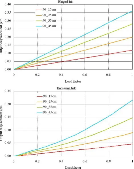
Fig. 4. Output displacement at the left column top for vertical load-ing (90◦) with different magnitudes: (a) hinged structure; (b) en-casing structure.
column) obtained when imposing a vertical displacement of magnitude 15 cm at the base of the column, is about 12 cm (red line in Fig. 4a), which is close to the analytical value of 11.25 cm (= 15∗3/4) proposed by Bird and co-workers. For
an imposed magnitude of 45 cm, the computed demand dis-placement is around 35 cm (blue line in Fig. 4a), which is to be compared to the analytical value of 33.75 cm (= 45∗3/4).
For the encasing case, we find that values of demand dis-placements are almost twice lower than the ones obtained for the hinged case (see Fig. 4b).
For the other parametric studies presented in this paper, we have considered the encasing case only, as it is the most common foundation type for buildings.
4.2 Parametric study on the inclination angles
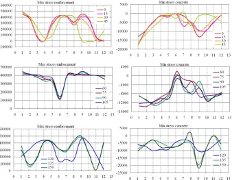
Fig. 5. Building stresses (in kPa) computed in the frame sections, for inclination angles of imposed displacements ranging from. 0◦to 150◦, and fixed magnitude (45 cm).
fy = 400 MPa. For concrete, damage occurs when the ab-solute value of computed compressive stress (i.e. minimum stress) is greater than the limit value fc = 21 MPa.
These results show that three classes of structure response can be derived with respect to the inclination angle (encasing case): 0◦–45◦; 45◦–105◦and 105◦–135◦. For any other angle within these intervals, the structure behaviour will not change considerably and the critical elements of the frame will be the same.
Within the first class (0◦–45◦), it seems that the behaviour of the frame structure is governed by the horizontal deforma-tion of the foundadeforma-tion, meaning that the vertical component (small in this class) can be neglected without consequences for damage evaluation.
Between 45◦ and 105◦ (2nd class), the vertical compo-nent of imposed displacements seems to govern the structure damage when imposing a large magnitude of displacements (e.g. 45 cm): the reinforcement stress distributions in frame sections are similar to the stress distributions for a vertical imposed displacement (90◦). Moreover, the frame sections are more stressed for a true vertical component (90◦) than for other angles within this class.
For the last class (above 105◦), we see that the response of the structure, in terms of stresses, has approximately the same trend and the most critical section is the bottom section of the right column, at which displacements are imposed.
4.3 Parametric study on the displacement magnitudes
In this study, we have considered varying imposed displace-ment magnitudes, incredisplace-menting by 10 cm from 15 to 45 cm, and fixing the inclination angle. However, different inclina-tion angles chosen within the three classes seen in Sect. 3.2, have been considered for analysis. Results for 30◦, 75◦and 135◦are presented in Fig. 6.
For inclination angles lower than 45◦(e.g. Fig. 6a), the in-crease in displacement magnitude leads to a maximum stress variation for both concrete and steel occurring essentially in frame Sect. 1, which corresponds to the bottom of the left column. This behaviour can be compared with the one of a simple bending cantilever. We also note that for a given mag-nitude, stress levels in Sect. 9 (bottom of the right column) are lower for 30◦than for 0◦(horizontal displacement). Fi-nally, except for the bottom sections of both columns, the other frame sections seem to be insensitive to the variation of displacement magnitude.
For all displacement magnitude and inclination angles be-tween 45◦and 105◦(e.g. Fig. 6b), the reinforcement reaches the yielding limit in all the studied frame sections (except Sect. 6), while the stresses in the concrete remain inferior to 16 MPa.
1788 C. Negulescu and E. Foerster: Vulnerability assessment of RC frame to settlements
Fig. 6. Example of building stresses (in kPa) computed in the frame sections, for different loading magnitudes and fixed inclination angles: (a) 30◦; (b) 75◦; (c) 135◦.
Fig. 7. Cross-section ratios (SR) considered for parametric analysis: SR = 2 (left), SR = 0.5 (centre), and SR = 1 (right).
4.4 Parametric study on the frame cross-section
In this last parametric study, we have considered different geometric dimensions for the frame cross-section, replacing the previous square section (section ratio SR equal to 1), by rectangular ones with SR = 0.5 and SR = 2 (see Fig. 7). The structure response was evaluated considering these three ra-tios and with different inclination angles. From the results, we observe that the most critical ratio corresponds to SR = 2. Moreover, for inclination angles inferior or equal to 30◦ or superior or equal to 135◦, this ratio leads to excessive yield stresses for concrete and reinforcement in bottom sections of both columns.
Comparing for instance, results obtained with ratios SR = 0.5 and SR = 2, considering various inclination angles and a fixed magnitude value of 15 cm, we note that the con-crete compressive stresses are lower for SR = 0.5 than for
SR = 2 (Fig. 8). In this latter case, the compressive yield is exceeded in critical Sects. 1 and 9 (i.e. bottom of the columns, as shown on Fig. 3).
4.5 Conclusion of the parametric studies
We have seen in the previous sections that displacement is a key parameter that can be considered as an intensity pa-rameter to establish the damages induced on the structure. By using an imposed displacement with varying magnitudes and/or inclination angles, it has been possible to identify the failure mechanism of the frame structure, knowing geomet-ric and material properties of the structures within a building class. Contrary to the seismic vulnerability assessment of frame structures, where two failure mechanisms are gener-ally considered (displacement capacities of column-sway or soft-storey; beam-sway or distributed damage), the previous parametric studies have shown that a column failure mecha-nism prevails in case of settlements.
Fig. 8. Example of building stresses (in kPa) computed in the frame sections for different section ratios (SR), considering a horizontal loading displacement (0◦) with fixed magnitude (15 cm).
Table 1. Limit strain states suggested by Bird and co-workers, for reinforcement steel and concrete materials, considering poorly and well confined buildings (see Bird et al., 2005a).
Limit Damage Limit strains
state definition
“Poor” Building “Good” building Steel Concrete Steel Concrete
LS1 Slight 0.002 0.002 0.002 0.002
LS2 Moderate 0.0125 0.0045 0.0125 0.0045 LS3 Extensive 0.0225 0.0075 0.0500 0.0150
5 Fragility curves
5.1 Identification of damage limit states
It is not frequent to have building failure due to differential settlements. Excessive foundation settlement is generally re-garded as a serviceability problem. There is rarely any prob-lem for human life, but rather the structure experiences dis-tress such as cracking of structural or architectural elements, uneven floors, or inoperable windows and doors.
A challenge in vulnerability assessment is to build some fragility curves, which express the probability of reaching a given damage state of the structure for a given intensity of hazard (e.g. differential displacements in our case). This fragility needs to be defined by means of objective crite-ria. Whereas some global damage indicators are widely used in seismic vulnerability assessment, no such criteria are yet available in the case of landslides.
In this paper, we have chosen the local damage indica-tors based on allowable values of material strains (concrete and steel), as proposed by Bird et al. (2005a,b). The corre-sponding limit strain states are given in Table 1, according to the quality of the construction. The first damage state, LS1 (slight damage), is directly connected to the strain at yield strength, which is 0.002 for both concrete and steel. First damage state LS1 and post-yielding damage states consid-ered in the present study, ranging from moderate (LS2) to complete (LS4) damage, are given in Table 2.
Table 2. Limit strain states proposed in this analysis for reinforce-ment steel and concrete materials.
Limit State Damage definition Limit strains
Steel Concrete
LS1 Slight 0.002 0.002
LS2 Moderate 0.015 0.004
LS3 Extensive 0.04 >0.006
LS4 Complete 0.06 –
5.2 Fragility curves
The fragility curves presented in Fig. 9 were obtained for the studied RC frame building considering the encasing case. Each curve gives the conditional probability of exceeding a specific limit state or level of damage (LS1 for yielding strain limit; LS2 to LS4 for post-yielding limit states, as defined in Table 2), over a range of ground motion intensity (differential settlements in our case).
A total of 55 cases were considered in our analysis, which include the variations of displacement magnitudes (maxi-mum value equal to 45 cm), inclination angles (from 0◦ to 150◦), degrees of reinforcement (0.5%, 0.7%, and 1%) and section ratios (SR = 0.5, 1, and 2).
Each fragility curve is obtained by counting, for different values of imposed differential settlementd (hazard parame-ter), the number of situations out of the 55 computed cases, that have led to the desired limit damage state LSk: these probabilities, represented by discrete points on Fig. 9, can then be fitted into a curve, usually representing the cumula-tive function of a normal distribution, as described by Shi-nozuka (1998) and ShiShi-nozuka et al. (2000). The functional form is presented in Eq. (1):
P[LS>LSk|d]=φ
lnαd
k
βk
(1)
whereφis the standard normal cumulative distribution func-tion. αk represents the median value, meaning that for
1790 C. Negulescu and E. Foerster: Vulnerability assessment of RC frame to settlements
Fig. 9. Fragility curves obtained for a one bay-one storey encasing RC frame building, considering 4 damage limit states: Slight (LS1), Moderate (LS2), Extensive (LS3) and Complete (LS4).
Table 3. Mean and standard deviation parameters computed for the four limit states (LSk) proposed in this analysis, and used to build the fragility curves.
Limit Damage Mean Standard State definition αk deviationβk
(cm) (cm)
LS1 Slight 5 0.5
LS2 Moderate 12 0.5
LS3 Extensive 27 0.5
LS4 Complete 40 0.5
in this damage state when a displacement of 5 cm is applied.
βkrepresents the dispersion of the curve (standard deviation)
for damage state LSk. A numerical optimisation allows to evaluate these statistical parameters. The values forαk and
βkcomputed in this analysis are provided in Table 3.
5.3 Validation of the proposed fragility curves
The validity of these analytical fragility curves has been ver-ified with some empirical curves derived from building ob-servations or expert judgment.
The empirical curves provided by Zhang and Ng (2005), are constructed by using values of the mean and standard de-viation of the limiting tolerable and intolerable settlements from 95 observations for which information on building, foundation and settlements were available. Table 4 provides a summary of the number of buildings (out the 95), observed in each state (“tolerable” or “intolerable” case), with respect to different settlements intervals, and considering different foundation types (shallow foundations only and all types of foundations). Table 5 gives the values for the corresponding mean and standard deviation parameters.
Table 4. Number of buildings out a total of 95, observed in each state (“tolerable” or “intolerable” settlement case), with respect to different intervals of settlement values, and considering different foundation types (adapted from Zhang and Ng, 2005).
Settlement Number of buildings interval per damage state
(cm)
All Shallow
foundations foundations Tolerable Intolerable Tolerable Intolerable
0–2.5 25 0 18 0
2.5–5 16 0 10 0
5.1–10 10 6 7 4
10.1–15 2 3 2 3
15.1–20 2 0 1 0
20.1–25 1 7 1 5
25.1–30 1 3 1 3
30.1–40 0 8 0 7
40.1–50 1 2 1 2
50.1–150 0 8 0 6
0–150 (all) 58 37 41 30
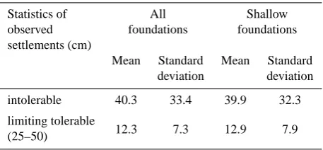
Table 5. Statistics of intolerable and limiting tolerable settlement and angular distortion of buildings (Zhang and Ng, 2005).
Statistics of All Shallow
observed foundations foundations
settlements (cm)
Mean Standard Mean Standard deviation deviation
intolerable 40.3 33.4 39.9 32.3
limiting tolerable
12.3 7.3 12.9 7.9
(25–50)
In Fig. 10, we show the comparison between these em-pirical curves and the analytical fragility curves proposed in this paper, considering the shallow foundation case. It can be seen that the curve built for limit state LS2 (moderate damage) is in good agreement with the empirical curve for tolerable settlements as proposed by Zhang and Ng (2005). The curve built for limit state LS4 (complete damage) corre-sponds to the observed intolerable settlements one.
In Fig. 11, we show also the comparison with the building damage functions to Permanent Ground Displace-ment (PGD) for shallow foundations, as provided by HAZUS (2003)1(values indicated in Table 6). These func-tions are based on engineering judgment related to building 1HAZUS-MH MR1, Multi-hazard Loss Estimation
Fig. 10. Comparison between the proposed analytical fragility curves and the empirical ones provided by Zhang and Ng, corre-sponding to the settlements observed on 95 buildings (see Zhang and Ng, 2005).
fragility. It can be seen that the HAZUS values proposed for settlements are in good agreement with the ones obtained from the proposed LS4 curve (complete damage), contrary to the lateral spread case. However, these comparisons seem encouraging, but we see that in order to further validate the proposed methodology and related fragility curves, there is a strong need of more observational data, actually lacking in current landslide databases or real case studies that can be useful for such analysis.
6 Discussion
All numerical simulations were carried out under a one-way static loading, which cannot account for the strength degradation due to cyclic loading. Hence, for a structure subjected to dynamic loading, the numerical model overes-timates the strength of the column beyond a certain number of cycles.
However, the numerical modelling approach allows to per-form parametric studies and hence, to investigate the in-fluence of different parameters on the structure response. Comparison of the results gives a better understanding of the structure behaviour, as well as possible damage assess-ment.
It may be argued that the chosen case study (RC frame building) is too simple to be representative for a real class of buildings. Nonetheless, such a simple structure is useful, as it allows focusing on key, but “basic” parameters, lead-ing to a better understandlead-ing of the structure behaviour. It permits hence to determine the possible methodology to be employed in order to assess damages. Once the procedure is well established and tested for a number of simple models, it is possible to further extend the methodology to more com-plex structures, adopting a probabilistic framework useful for practical applications.
Fig. 11. Comparison between the proposed analytical fragility curves and the building damage functions to Permanent Ground Displacement (PGD) for shallow foundations, as proposed by HAZUS (2003)1.
Table 6. Building damage relationship to Permanent Ground Dis-placement (PGD) for Shallow Foundations (adapted from HAZUS, 20031), for Complete (C) and Extensive (E) damages.
P[E or C|PGD] Settlement Lateral PDG Spread PGD
(cm) (cm)
0.1 5.1 30.5
0.5 (median) 25.4 152.4
7 Conclusions
Our main objective in this work was to establish analyti-cal fragility curves useful for landslide vulnerability assess-ment (differential settleassess-ments in this case), with respect to a selected intensity-measure parameter. For this purpose, a number of parametric studies have been carried out, which consisted in 2-D nonlinear static time-history analyses per-formed on a simple one bay-one storey reinforced concrete (RC) frame structure, in order to identify one or several re-sponse parameters that govern the structural behaviour when subjected to differential settlements. The considered input aggression, which increased linearly up to an imposed value, was a displacement applied directly at the bottom of the right column in the frame plane, neglecting the soil-structure inter-actions.
1792 C. Negulescu and E. Foerster: Vulnerability assessment of RC frame to settlements Within the first class (0◦–45◦), it seems that the behaviour
of the frame structure is governed by the horizontal deforma-tion of the foundadeforma-tion, meaning that the vertical component (small in this class) can be neglected without consequences for damage evaluation.
Between 45◦and 105◦(2nd class), the vertical component of imposed displacements seems to govern the structure dam-age. Moreover, the frame sections are more stressed for a true vertical component (90◦) than for other angles within this class.
For the last class (105◦–135◦), it has been shown that the most critical section is the bottom section of the right col-umn, at which displacements were imposed.
A challenge for landslide vulnerability assessment is to de-fine some damage limit states that may be wildly recognised as for those defined in seismic vulnerability assessment. At-tempts to define such limit states have been made and a way is to specify allowable values of concrete and steel strains for the considered structure type.
Finally, the deterministic results obtained from the para-metric studies were used in order to built analytical fragility curves. The first comparisons of the proposed curves with empirical ones found in literature, lead to a quite good agree-ment, but the proposed methodology and related fragility curves need still to be further validated with more observa-tional data, relevant for such analysis and which is actually lacking in current landslide databases or real case studies. Acknowledgements. This work was supported by the European project LESSLOSS (No. GOCE-CT-2003-505488) and BRGM under grant RISR17-VULNERISK.
Edited by: M. Contadakis Reviewed by: M. Jaboyedoff
References
ATC 40: Seismic evaluation and retrofit of concrete buildings, Ap-plied Technology Council, Redwood City, California, 1996. Beeby, A. W. and Miles, J. R.: Proposals for the control of
deflec-tion in the new unified Code, Concrete, 3(3), 101–110, 1969. Bird, J. F., Crowley, H., Pinho, R., and Brommer, J. J.:
As-sessment of building response to liquefaction-induced differen-tial ground deformations, Bull. New Zealand Soc. Earthq. Eng., 38(4), 20 pp., 2005a.
Bird, J. F., Brommer, J. J., Crowley, H., and Pinho, R.: Modelling liquefaction-induced building damage in earthquake loss estima-tion, Soil Dyn. Earthq. Eng., 26, 15–30, 2005b.
Bjerrum, L.: Allowable Settlement of Structures, in: Proceedings of the 3rd European Conf. on Soil Mech. and Found. Engng, Wies-baden, 2, Brighton, England, 135–137, 1963.
Boone, S. J.: Ground-Movement-Related Building Damage, J. Geotech. Eng.-ASCE, 122(11), 886–896, 1996.
Boscardin, M. D. and Cording, E. G.: Building Response to Exca-vation Induced Settlement, J. Geotech. Eng.-ASCE, 115, 1–21, 1989.
Burd, H. J., Houlsby, G. T., Augarde, C. E., and Liu, G.: Modelling tunnelling-induced settlement of masonry buildings, in: Proc. In-stitution of Civil Engineers, Geotech. Engng, paper 11831, 143, 17–29, 2000.
Burland, J. B. and Wroth, C. P.: Settlement of Buildings and Asso-ciated Damage, in: Proceedings of the Conference on Settlement of Structures – Session V, Cambridge, England, 611–654, 1974. Combescure, D.: Mod´elisation des structures de g´enie civil sous chargement sismique a l’aide de CASTEM 2000, Report DM2S, 122 pp., 2001 (in French).
Deck, O., Al Heib, M., and Homand, F.: Taking the soil-structure interaction into account in assessing the loading of a structure in a mining subsidence area, Eng. Struct. 25, 435–448, 2003. Douglas, J.: Physical vulnerability modelling in natural hazard
risk assessment, Nat. Hazards Earth Syst. Sci., 7, 283–288, doi:10.5194/nhess-7-283-2007, 2007.
Finno, R. J., Voss, F. T., Rossow, E., and Blackburn, J. T.: Evalu-ating Damage Potential in Buildings Affected by Excavations, J. Geotech. Geoenviron., 131(10), 1199–1210, 2005.
Glade, T.: Vulnerability assessment in landslide risk analysis, Die Erde, 134, 121–138, 2003.
IUGS: Quantitative risk assessment for slopes and landslides - The state of the art, in: Proceedings of the International Workshop on Landslide Risk Assessment, International Union of Geological Sciences (IUGS), Working Group on Landslides, Committee on Risk Assessment, Honolulu, Hawaii, USA, 3–12, 1997. Koutsourelakis, S., Pr´evost, J. H., and Deodatis, G.: Risk analysis of
an interacting structure-soil system due to liquefaction, Earthq. Eng. Struct. D., 31, 851–879, 2002.
Mander, J. B., Priestley, M. J. N., and Park, R.: Theoretical stress-strain model for confined concrete, J. Struct. Eng.-ACSE, 114(8), 1804–1826, 1988.
Polshin, D. E. and Tokar, R. A.: Maximum Allowable Non-uniform Settlement of Structures, in: Proc. 4t hInt. Conference Soil Me-chanics and Foundation Engineering, London, Butterworths Sci-entific Publications, 402–405, 1957.
R¨usch, H. and Maye,r H.: Bauschaden als Folge der Duchbiegung von Stahlbeton-Bauteilen, Deutscher Ausschuss fur Stahlbeton, Berlin, No. 10, 1964 (in German).
SeismoSoft: SeismoStruct – A computer program for static and dynamic nonlinear analysis of framed structures, available at: http://www.seismosoft.com (last access: 2007), 2003.
Shinozuka, M.: Statistical analysis of bridge fragility curves, Pro-ceedings of the US-Italy Workshop on protective systems for bridges, New-York, USA, 249–256, 1998.
Shinozuka, M., Feng, M. Q., Lee, J., and Naganuma, T.: Statistical analysis of fragility curves, J. Eng. Mech.-ASCE, 126(12), 1224– 1231, 2000.
Skempton, A. W. and MacDonald, D. H.: Allowable Settlement of Buildings, P. I. Civil Eng., 5, Part III, 727–768, 1956.
Sowers, G. F.: Shallow Foundations, in: Foundation Engineering, edited by: Leonards, G. A., McGraw-Hill Book Co., New York, NY, USA, 525–632, 1962.