National Conference on Advances in Engineering and Applied Science (NCAEAS) 16th February 2017
In association with
I
nternational
Journal
of
Scientific
Research in
Science and
Technology
Performance Analysis of phase shifted SPWM Technique for Three
Phase Diode Clamped Three Level Inverter
Anirudha Gedam, Saurabh Rahangdale, Shaharukh Pathan
Department of Electrical Engineering, Anjuman College of Engineering & Tech, R.T.M. Nagpur
University, Nagpur, Maharastra, India.
ABSTRACT
The Primary function of VSI is to convert fixed DC voltage into variable AC voltage at required voltage and frequency. The diode-clamped multilevel inverter employs clamping diodes and cascaded dc capacitors to produce ac voltage waveforms with multiple levels. The inverter can be generally configured as a three-, four-, or five-level topology, but only the three-level inverter, often known as neutral-point clamped (NPC) inverter, has found wide application in high-power medium-voltage (MV) drives. The dc input voltage of the inverter is normally split by two cascaded dc capacitors, providing a floating neutral point. The control of the neutral-point voltage deviation is also elaborated.The dc supplies are normally obtained from multipulse diode rectifiers. Phase shifted PWM Technique is analyzed and its performance will be compared. Simulation results will be presented to analyze the performance of the PWM techniques. The simulation results will be verified using experimental results
Keywords : SPWM, MV, DC, NPC, PWM, VSI, ASD, UPS, FACTS, SHE
I.
INTRODUCTION
Inverter is device which converts electrical energy in DC form into AC form. The main objective of static power converters is to produce an AC output waveform from a dc power supply. These are the types of waveforms required in adjustable speed drives (ASDs), uninterruptible power supplies (UPS), static VAR compensators, active filters, flexible ac transmission systems (FACTS) and voltage compensators. The primary function of a voltage source inverter (VSI) is to convert a fixed dc voltage to three-phase ac voltage with variable magnitude and frequency.
In voltage source inverter thyristor, IGBT, MOSFET, GTO can be used as switches. Generally thyristor are not used because they require forced commutation. Single-phase voltage source inverters (VSIs) and current source (CSIs) can be found as half-bridge and full-bridge topologies.
II.
METHODS AND MATERIAL
A. Need of three Level Inverter
The output voltage contains higher values of Total
Harmonic Distortion(THD), hence fundamental
controls the amount of time and the sequence used to switch the power valves on and off. The modulating techniques most used are the carrier-based technique (e.g., sinusoidal pulse width modulation, SPWM), the space-vector (SV) technique, and the selective-harmonic-elimination (SHE) technique, phase shifted pulse width modulation. The discrete shape of the ac output waveforms generated by these topologies imposes basic restrictions on the applications of inverters.
B. Three Phase Diode Clamped Three Level Inverter
In the recent past the multilevel power converters have drawn a tremendous interest in the field of high voltage and high power applications field in industries. The multilevel inverter approach allows the use of high power and high voltage electric motor drive systems. Using the multilevel inverter concept, a divide and conquer approach allows more flexibility and control over the discrete components that makeup the system. In the researches on multilevel inverters, their corresponding PWM control strategies are the emerging research areas. In high power and high voltage applications, the two level inverters, however, have some limitations in operating at high frequency mainly due to switching losses, dv/dt and di/dt stresses in power semiconductor devices and constraint of the semiconductor power device ratings. For high voltage applications two or more power devices can be connected in series to achieve the desired voltage ratings and in parallel to achieve the current ratings. Multilevel inverters can increase the power by the series connection of power semiconductor devices.
Working
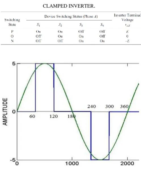
SWITCHING STATE OF THE THREE-LEVEL DIODE CLAMPED INVERTER.
Figure 2. Desired pole voltage for three level
3.SINUSOIDALPULSEWIDTHMODULATION
Sinusoidal pulse width modulation is a method of pulse width modulation used in inverters. An inverter produces an AC output voltage from a DC input by using switching circuits to simulate a sine wave by producing one or more square pulses of voltage per half cycle. If the widths of the pulses are adjusted as a means of regulating the output voltage, the output is said to be pulse width modulated.
With pulse width modulation, only the widths (on-time) of the pulses are modulated. The amplitudes (voltage) during the "on-time" is constant unless a multi-step circuit is used. The line-to neutral voltage of a 3-phase inverter has two voltage levels.
Figure 3. Comparison of Sine and triangular wave for Three Level
SPWM
Phase shifted SPWM Technique
In general, a multilevel inverter with m voltage levels requires (m – 1) triangular carriers. In the phase-shifted multicarrier modulation, all the triangular carriers have the same frequency and the same peak-to-peak amplitude, but there is a phase shift between any two adjacent carrier waves, given by
Φcr = 360°/ (m – 1)
The modulating signal is usually a three-phase sinusoidal wave with adjustable amplitude and frequency. The gate signals are generated by comparing the modulating wave with the carrier waves.
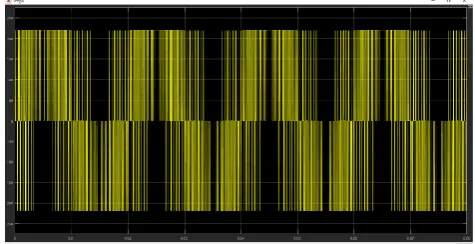
Figure 4. Phase shifted sinusoidal PWM modulation.
Figure 2. Spectrum Analysis of Phase shifted sinusoidal PWM modulation.
MATLAB Simulation results for phase shifted SPWM Technique for Three Phase Diode Clamped Three Level Inverter.
Figure 6. Circuit diagram of three level inverter.
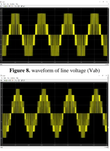
Figure 8. waveform of line voltage (Vab)
Figure 9. waveform of load voltage (Vl)
III.
RESULTS AND DISCUSSION
ADAVANTAGES OF THREE-LEVEL DIODE
CLAMPED INVERTER.
The Three-level diode clamped inverter has a several advantages that is
1. Common mode voltage: The multilevel inverter produce common mode voltage reducing the motor and don’t damage the motor
2. Input current: Multilevel inverter can draw input current with low distortion.
3. Switching Frequency: The multilevel inverter can operate at both fundamental switching frequencies that are higher switching frequency and lower
becomes low in the output waveform without using any filter circuit.
APPLICATIONS OF THREE LEVEL INVERTER
Multi-level (Three level) inverters have been developed for electric utility applications.
1. Three level inverters used in static VAR compensators.
2. It enables direct parallel or series transformer-less connection to medium- and high-voltage power systems.
3. Three level inverter can be used for power supply, (hybrid) electric vehicle (EV) motor drive, reactive power (VAR) and harmonic compensation.
IV.
CONCLUSION
In phase shifted SPWM the lower order harmonics are almost eliminated and also power consumed by each switch is almost same. Hence phase shifted PWM technique is used.
V.
ACKNOWLEDGMENT
We are very much please to submit present “Project Report”. It has been prepared in compliance with the course in “Electrical Engineering”, set by the university curriculum. The guidance of our honorable guide has not left untouched a single page of our report and helped as a great deal in completing on time.
We are grateful to our Prof. RUHI UZMA SHEIKH Ma‟ am for giving constant encouragement and guidance. We extend our thanks to Principal Dr.Sajid Anwar who is our source of inspiration and extended every facility to us.
VI.
REFERENCES
[1]. P. Palanive, Subhransu Sekherdash, "Phase Shifted Carrier Pulse Width Modulation For Three Phase Multilevel Inverter to Minimize THD and Enhance Output Voltage Performance", JES,2010.
[2]. Sachin Maheshari, Prabodh Khampariya,
"Simulation of Single Phase SPWM Inverter" , IJIRAE, vol-1, oct-2014.
[3]. Rajesh Kumar Ahuja, Amit Kumar, "Analysis, Design and Control of Sinusoidal PWM Three Phase Voltage Source Inverter Feeding Balanced Loads at Different Carrier Frequencies Using MATLAB," IJAREEIE vol-3, may-2014.
[4]. Bin Wu, "High Power Converter & AC Drives" , pp. 95-142.