© 2018 IJSRST | Volume 4 | Issue 2 | Print ISSN: 2395-6011 | Online ISSN: 2395-602X Themed Section: Science and Technology
Tilt Angle Detector Using 3-Axis Accelerometer
R. Rajesh*1, I. Baranilingesan2
1Department of Electrical Anna University, Regional Campus: Coimbatore, Coimbatore, Tamil Nadu, India 2Electronics Engineering, Anna University, Regional Campus: Coimbatore, Coimbatore, Tamil Nadu, India
ABSTRACT
This paper describes accelerometer, which is an electromechanical device that can be used for various applications like tilt detection, obstacle detection, motion inputs, earthquake sensing, etc. Tilt detection is a simple application of an accelerometer where a change in angular position of the system in any direction is detected and indicated the corresponding angle scaled from microcontroller output. In this article utilize the ADXL335 3-axis accelerometer for tilt measurement and error is calculated from the actual desired position. This article also studies the merits and demerits of one axis and two axis tilt measurement using an accelerometer. An arduino Uno board and arduino software are used to process the data received from the accelerometer.
Keywords : Accelerometer, Tilt Angle, 3-Axis, Direction, Arduino Uno.
I.
INTRODUCTION
Accelerometer is an electromechanical device provides the information of forces acting on or experienced by the object. Once the acceleration of the object in each dimension is obtained, successive integral computations can be used to calculate the velocity and distance covered by the object. The rate of change of velocity gives the acceleration which can be interpreted as the tilt angle.
Micromachined accelerometers belonging to Micro electro mechanical system (MEMS) is utilized in this work, due to their lesser dimensions (less than 2 mm), high reliability, easy integration with electronics devices, acceptable accuracy, high shock resistance, low power consumption and low cost [1]. They realize several types of accelerations such as derivatives (jerk, jounce), integrals (velocity, position), etc.
In recent the development of technology, unexpected applications emerge continuously, for example, underwater equipment, aerospace devices, watches,
scuba diving equipment, new generation motorcycles, traction control system and navigation systems, for this kind of applications accelerometer, plays an important role [2-4].
The 3-axis accelerometer is the most preferable accelerometer for tilt measurement because of the alignment error sensitivity axis below 0.01o[9]. A
modest tilt measurement application can be realized using a microcontroller to input the analog output voltage of accelerometer and general purpose I/O pins for displaying the degrees either on a PC through a communication protocol or on an LCD. An arduino uno board which is a microcontroller board based on ATmega 328, is used to process the data received from accelerometer and display the tilt through LED blinking and LCD display. Arduino is an open-source electronics prototyping platform based on flexible, easy-to-use hardware and software. Its intend for artists, designers, hobbyists, and anyone interested in creating interactive objects or environments.
The rest of this paper is organized as follows: a review of tilt measurements and techniques are introduced in section 2. In section 3, ADXL335 MEMS accelerometer principle is reviewed. In section 4 hardware implantation of 3-axis accelerometer is described. In section 5 result and conclusion and section 6 conclusion are shown.
II.
REVIEW OF TILT MEASUREMENTS AND
TECHNIQUES
One of the general methods for sensing tilt or inclination is to integrate the output of gyroscope. Although the use of gyroscope is a direct method, the error related with null bias stability can be complex if the integration period is increased. This can cause an apparent rotation even when the device is static. In applications such as gaming, horizon detection in digital cameras and detecting the head of the device in industrial and medical applications, the net acceleration or force on the system over is gravity. An accelerometer can be used for determining the static angle of tilt or inclination in the above mention applications [10].
Inclination sensing uses gravity vector and its projection on the axes of the accelerometer to govern the tilt angle. Because the gravity is a static acceleration, at any force that results in an extra static acceleration corrupt the output signal and results in an improper calculation. Sources of static acceleration include the period of time when a vehicle is accelerating at a constant rate and rotating device that include a centripetal acceleration on the accelerometer. In addition, rotating an accelerometer through gravity causes apparent ac acceleration as the projection of gravity on the axes of interest change. Any filtering of the acceleration signal before calculating the inclination affects the speed at which the output settles to the new static value.
A. Measuring Tilt Using One Axis
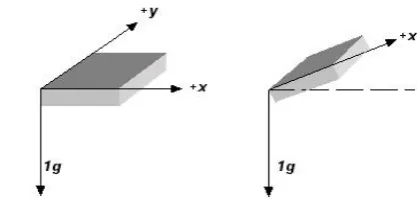
As in the case of a dual axis accelerometer (XY) is fixed and perpendicular to gravity, the tilt algorithm is restricted to one axis of sensitivity [10]. The accelerometer is tilted along the X-axis and Y-axis remains at 0g output during the full rotation of the X-axis as shown in Figure 1.
Figure 1. Dual axis accelerometer with one axis of tilt
If one axis (X-axis) is used to analyze the tilted angle of the accelerometer the following trigonometry association is used.
V S sin
VOFF OUTX (1)
where, VOFF is the offset voltage, VOUTX is the voltage
The accelerometer output on the X-axis due to gravity is equal to the following,
S V V
A OUTX OFF
x
(2)
In order to solve for the angle of tilt (1) becomes,
x1 A
sin
(3) In this arrangement tilt sensitivity between -900 and
-450 and between +900 and +450. This resolution
problem between these values makes this method calculation of the tilt angle inaccurate when the accelerometer output is near the +1g or -1g range. Another disadvantage of the single axis tilt measurement method is difficult to identify the variance between two tilt angles that outcome in the similar sensor output. This disadvantage is overcome by using a two axis measurement tilt technique.
B. Measuring Tilt Using Two Axis
The resolution problems and tilt orientation problems can be addressed by mounting the accelerometer vertically. So that the Y-axis is parallel to gravity or by using a tri-axis accelerometer using at least 2 of the 3 axis. Using more than one axis to calculate tilt produces a more accurate solution as shown in Figure 2.
Figure 2. Dual axis accelerometer with one axis of tilt
The first major benefit of using a second axis is due to the orthogonality of the axes. As in the single axis solution, the acceleration detected by the x-axis is proportional to the sine of the angle of inclination. The Y-axis acceleration, due to the orthogonality, is proportional to the cosine of the angle of inclination.
One method, to convert the measured acceleration to an inclination angle is to compute the inverse sine of the X-axis and the inverse cosine of the Y-axis, similar to the single-axis solution. However, an easier and more efficient approach is to use the ratio of the two values, which results in the following,
g 1 cos
g 1 sin A
A
OUTY OUTX
(4)
OUTY OUTX 1
A A tan
(5)
Where the inclination anglesis in radians.
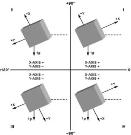
The second major benefit of using at least two axes is that unlike the single-axis solution, where tilt in any axis other than the X-axis can cause significant error, the use of a second axis allows for an accurate value to be measured even when inclination in the third axis is present. The third major benefit of using a second axis is the ability to distinguish between each quadrant and to measure angles throughout the entire 3600 arc
as shown in Figure 3.
The correct quadrant of the calculated angle can be determined by examining the sign of the measured acceleration on each axis.
The dual-axis acceleration is most responsive to changes in tilt when the sensitive axis is perpendicular to force of gravity and least responsible to change tilt when the sensitive axis is oriented in +1g or –1g position. Also accelerometer cannot indicates detection of inversion due to the absence of Z-axis and causing improper functioning [10].
C. Measuring Tilt Using Three Axis
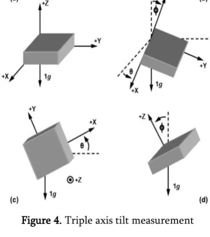
In order to define the angles of the accelerometer in three dimensions the pitch, roll and theta are sensed using all three outputs of the accelerometer as shown in Figure. 4. Pitch () is defined as the angle of the X-axis relative to ground. Roll () is defined as the angle of the Y-axis relative to the ground. Theta () is the angle of the Z axis relative to gravity [10].
Figure 4. Triple axis tilt measurement
y Sensitivit Zero n ref X X V V 1 2 V V R
(6)
y Sensitivit Zero n ref Y Y V V 1 2 V V R
(7)
y Sensitivit Zero n ref Z Z V V 1 2 V V R
(8)
2 Z 2 Y 2
X R R
R
R (9)
R R cos a 1 X
(10)
R R cos
b 1 Y (11)
R R cos c 1 Z
(12)
The value of VZero, VRef and VSensitivity are obtained
from the datasheet of ADXL335.
III.
REVIEW OF ADXL335 MEMS
ACCELEROMETER
An accelerometer is an electromechanical device that measures accleration forces. These forces are may be static or dynamic. By measuring the amount of static acceleration due to gravity the tilted angle with respect to earth can be obtained. Using the dynamic acceleration the device movement is analysed. The ADXL335 accelerometer used for tilt detection in this article. An Arduino Uno board is used to process the data received from the accelerometer.
The ADXL335 is a complete small, thin, low power, complete 3-axis MEMS based accelerometer with signal conditioning voltage outputs accelerometer measurement system as shown in Figure 5. The ADXL335 has a measurement range of 3g
minimum. It contains a polysilicon surface-micromachined sensor and signal conditioning circuitry to implement an open-loop acceleration measurement architecture. The output signals are analog voltages that are proportional to acceleration. The polysilicon surface-micromachined structure built on top of a silicon wafer. This polysilicon springs suspend the structure over the surface of the wafer and provide a resistance against acceleration forces. Deflection of the structure is measured using a differential capacitor that consists of independent fixed plates and plates attached to the moving mass. The fixed plates are driven by 1800 out of phase square
unbalances the differential capacitor resulting in a sensor output whose amplitude is proportional to acceleration. Phase sensitive demodulation technique is then used to determine the magnitude and direction of the acceleration. The demodulator output is amplified and brought off chip through 32 kΩ resistor. The user then sets the signal bandwidth of the device by adding a capacitor. This filtering improves measurement resolution and helps prevent aliasing [11].
Using an aditional temperature compensation circuitry, innovative design technique ensure that high performance is built in to the ADXL335. As a result, there is no quantization error or non-monotonic behavior and very low temperatiure hysteresis (typically less than 3 mg over the -25oC to
+70oC temperature range) [12]
Figure 5. Functional block diagram of ADXL335
IV.
HARDWARE IMPLEMENTATION
The implementation of the circuit includes accelerometer module (ADXI335), Arduino Uno board, LEDs and LCD display as shown in Figure 6.
Figure 6. Block diagram of tilt detector
The testing procedure for tilt measurement as follows,
1. After assembling the circuit, first need to trigger values for LEDs and for that:
a) Burn the test code on the arduino uno board. b) Open the serial port from arduino
environment and press reset button
c) Possible to see the screen on which the values of X, Y and Z axes will vary corresponding to the position of the accelerometer
d) Tilt it to the left and note the value for ‘A_max’ after which want the corresponding LED to glow. The same trigger will be applied for backward tilt too e) Tilt it to the right and note the value for
‘A_min’ after which want the corresponding LED to glow. The same trigger will be applied for backward tilt too 2. The trigger values are defined by ‘A_max’ and
‘A_min’ in the tilt detection code
3. Write the tilt detection code and open it in Arduino software
4. Enter the values for ‘A_max’ and ‘A_min’ in the final code
5. If the angular tilt is within the threshold, LED will not glow. Otherwise, LEDs corresponding to each direction will glow
7. Similarly possible to see the corresponding tilt indication and angle display in LCD display
V.
RESULTS AND DISCUSSION
The results of this tilt detection are obtained by giving a tilt to the accelerometer and blinking the respective LED with a LCD display indicating the direction, ADC output and corresponding angle. The procedure for measuring tilt angle is used in this article as follows: 1. The tilt of the accelerometer is given with respect
to a known angle measured on a protractor scale 2. The microcontroller obtains the analog values and
displays an ADC output for the corresponding axis or direction
3. The ADC output of microcontroller is scaled first to a respective voltage level and then subsequently to an angle mathematically
A.Tilt Measurement For Left Direction (Y-axis)
1. Initially, the accelerometer is tiled slightly towards its left direction. Once when the tilt angle provided exceeds the limit specified, the corresponding LED glows as shown in Figure 7 2. The angle tilted manually is noted using a
protractor and is tabulated as actual angle
3. Later the ADC values displayed by the microcontroller for all three axes are taken and substituted in (6), (7) and (8) in obtaining R value is displayed on LCD
4. The obtained R value is substituted in the (11) to obtain the corresponding angle in degree
Figure 7. Result of the left tilt
B. Tilt Measurement For Right Direction (Y-axis)
1. Initially the accelerometer is tilted slightly towards its left direction. Once when the tilt angle provided exceeds the limit specified, the corresponding LED glows as shown in Figure 8 2. The steps 2 , 3 and 4 mentioned for angle
measurement in Left direction is followed to obtain the respective angle in Right direction
Figure 8. Result of the right tilt
C. Tilt Measurement For Forward Direction (X-axis)
1. Initially the accelerometer is tilted slightly towards its left direction. Once when the tilt angle provided exceeds the limit specified, the corresponding LED glows as shown in Figure 9 2. The steps 2 and 3 mentioned for angle
measurement in Left direction is followed to obtain the R value
3. The obtained R value is substituted in equation (10) in order to find the tilt angle in forward direction along x-axis
D. Tilt Measurement For Backward Direction (X-axis)
1. Initially the accelerometer is tilted slightly towards its left direction. Once when the tilt angle provided exceeds the limit specified, the corresponding LED glows as shown in Figure 10 2. The steps 2 , 3 and 4 mentioned for angle
Figure 9. Result of the forward tilt
Figure 10. Result of the backward tilt
E. Tilt Measurement For Neutral Direction
1. When no tilt is given to the accelerometer or when the tilted angle is within the limit specified none of the LEDs glow and the display indicates neutral as shown in Figure 11
2. Since no specific axis can be assured the neither the microcontroller nor the angle is calculated or displayed
Figure 11. Result of neutral
Experimental results are tabulated in TABLE I and error is calculated from the actual angle to displayed angle.
Table 1. Result for tilt angle detection
Direction
Actual angle (degree)
Theoretical angle (degree)
Displayed angle (degree)
Error
Left 54 53.05 52.60 0.025 Right 67.5 66.34 65.88 0.019 Forward 63.5 63.12 62.76 0.011 Backward 56.5 55.93 55.40 0.019
VI.
CONCLUSION
The tilt of the accelerometer is compared with three different ways like actual value, theoretical value and displayed value. As the theoretical value calculated describes the conversion of ADC output to the corresponding angle which actually the microcontroller does, hence the error between the actual value and displayed value is obtained. The error obtained was acceptable and is minimum. Hence, with the obtained results of 3-axis accelerometer has proven that effective in measuring the tilt angle. The merits and demerits of one-axis and two-axis accelerometer also studied. The use of MEMS technology based accelerometer is increased due to its sensitivity, more accurate and reliable.
VII.
REFERENCES
[1]. Abbate N, Basile A, Brigante C, Faulisi A, La Rosa F. Modern breakthrough technologies enable new applications based on IMU systems. Journal of Sensors. 2011;2011.
[2]. Luczak S. Tilt measurements in BMW motorcycles. InRecent Global Research and Education: Technological Challenges 2017 (pp. 287-293). Springer, Cham.
[4]. Ali A, El-Sheimy N. Low-cost MEMS-based pedestrian navigation technique for GPS-denied areas. Journal of Sensors. 2013;2013.
[5]. Wilson JS. Sensor technology handbook. Elsevier; 2004 Dec 21.
[6]. Fatikow S, Rembold U. Microsystem technology and microrobotics. Springer Science & Business Media; 2013 Apr 17.
[7]. Bodnicki M, Sęklewski M. Design of small-outline robot-simulator of gait of an amphibian. InRecent Advances in Mechatronics 2007 (pp. 77-81). Springer, Berlin, Heidelberg.
[8]. Bodnicki M, Kamiński D. In-pipe microrobot driven by SMA elements. InMechatronics 2013 2014 (pp. 527-533). Springer, Cham.
[9]. Luczak S, Grepl R, Bodnicki M. Selection of MEMS accelerometers for tilt measurements. Journal of Sensors. 2017;2017.
[10]. Fisher CJ. Using an accelerometer for inclination sensing. AN-1057, Application note, Analog Devices. 2010 Feb.