A Tool Set to Support Web Application Testing
Ji-Tzay Yang, Jiun-Long Huang, Feng-Jian Wang
Department of Computer Science and Information Engineering
National Chiao-Tung University, Taiwan, ROC
Email: {jjyang,jlhuang,fjwang}@csie.nctu.edu.tw
Abstract
The development and deployment of Web-based applications are getting prevalent in the Internet and Intranet environment. A Web-based application usually requires programming for both web servers and browsers. Several frameworks and techniques have been proposed to ease the development of web-based application. For example, Microsoft InterDev and FrontPage are provided to support software development of such style. However, few tools are provided to directly support the software testing on Web-based applications.
In this paper, a set of software tools is proposed to support the testing of web-based applications. The tool set covers application model extraction, test execution automation, and test design automation. In addition, a graph-based application model is also presented to model the behavior of web-based applications. With the graphic presentation, several traditional software testing techniques are extended to test Web-based applications.
1. Introduction
The Web-based applications becomes popular due to the highly-available Internet access and widespread deployment of Web browsers on most platforms of operating environments. More and more applications which need to be platform independent and distributed processing rely on the Web as the software architecture. Applications such as on-line shopping system, on-line registration system, or process management system are typical examples which are implmented under the Web architecture. Several development frameworks have been built to assist Web applicaton developers. In the frameworks, Web applications are developed under client-server model, three-tier model, or even n-tier model. Besides, lots of software components which can be directly applied or customized are provided to perform interaction at Web browser and database connection at the Web server. Behaviors and glues of components are described in scripting language such as JavaScript or Microsoft VBScript.
Web application developers can build Web applications under the assistance of proper frameworks and software components. However, they have not sufficient and powerful tools to debug or test their Web applications. [9] also addressed the neccesity of software testing support to handle complexity of the Web applications. Only a few commercial products have been
announced to support Web applications testing[20]. Some of them test the software components such as JavaApplet and Active X objects which are embedded in the Web pages[18][19]. Some extend traditional GUI testing tools to test the GUI events inside the Web browsers. Some help justify the result shown on the Web browser’s window by matching text patterns or pixel-level comparison. Some check the documents for syntax and compatibility to popular Web browsers.
Current Web testing tools are mainly made to verify the syntax in HTML documents, check hyperlink integrity in a set of HTML documents, test GUI components embedded in browsers, and measure the performance of the Web application. Few testing tools consider Web application’s control and data flow via static and dynamic analysis. There are still some significant characteristics of Web applications need to be studied, such as the control and data dependency of Web application’s programming modules. This paper proposes a Web application model by extending control flow graph to model Web application’s control. The extended model is further used to generate test cases by applying traditional flow-based test cases generation techniques. In addtion, an integrated Web application testing environment is implemented to help Web testing staffs (1) design or generate test cases to reveal potential Web-related bugs, and (2) automate the test case execution to avoid repetitious manual input.
This paper is organized as follows. Section 2 reviews the current approaches to implement Web applications. Section 3 describes the behavior model for Web applications. Section 4 describes the testing environment and its tool set, which includes test case capture tool, composition tool, execution tools, and load testing tools. Finaly, section 5 gives conclusion and future works of the web application testing environment.
2. Characteristics
of
Web
Applications
Web applications are composed of static HTML documents and programs run at both server and client sides. HTTP (Hyper-Text Transfer Protocol) is used for communication between Web browsers and Web servers. Web servers and database servers are usually connected by de facto database access protocols such as ODBC (Open Database Connection) or JDBC (Java Database Connection). The following subsections introduce the architecture overview and activities involved in the Web applicaitons implementation. Meanwhile, the desired testing support are also addressed.2.1. Web Application Architecture
Web application architecture shown in Figure 1 is supported by current Web-related techonologies. It consists of three major tiers, the Web browser, the Web server, and optional database servers. The information process in the application is passed throught each tier. The user interaction is performed at the Web browser tier. The program logic is done at the Web server tier. The database processing is done at the database server tier. Hence, the Web application architecture is also known as a three-tier
application architecture. When the database server tier is omitted, it is known as a two-tier application architecture.
Augmented HTML Document Database Server Socket/ RMI/ CORBA
Image, Sound, Animation Plain HTML Document Java Applet Database Access Protocol Server Side Intepreter Web Browser Web Server Database Server Java VM Java Script Intepreter Plug-In Processor HTML Render CGI Programs Network Application Server F r o n t E n d Tier Protocol / Interface Information Flow Information Processor DocumentWeb
Legend Legend Legend Legend Common Gateway Interface (CGI) HTTP Database Access Protocol Database Access Protocol Database Access Protocol
Figure 1. Web Application Architecture
The Web browser is capable of retrieving hyper-text documents, as requested by the application users, from the Web server via HTTP protocol. It renders the hyper-text document in HTML (Hyper-Text Markup Language) format on the screen. Contemporary Web browsers also embed Java VM and interpreter to execute the Java Applets or Java Scripts specified in the documents. The browser also allows users to extend its functionality by installing additional software modules such as Netscape Communicator’s plug-in modules and Microsoft Explorer’s ActiveX objects.
The Web server has a frontend (HTTP daemon) to accept the HTTP requsets from the browsers. Accroding to the server’s configuration, it may directly serve the stored HTML documents, Java Applets, or multimedia files, or forwards the requests to CGI programs, by which the HTML documents to be returned are generated dynamically. Some Web servers also have modules [4][11] to interprete the augmented HTML documents before sending them to browsers.
In advanced Web applications, components in Web browsers may communicate with other components in the Web servers with protocols which are not HTTP. For example, components in the browser can communicate with standalone network application servers which run at the server-side by network sockets, Java RMI (remote method invocation), or CORBA. These emerging protocols are more fitting when developing distributed Web application in object-oriented technology.
2.2.
Programming at Web Clients
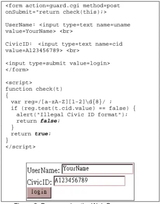
Web client programming focuses on the visual presentation and user interaction. The program guides the user to input data and validates user’s input before submitting it to the Web server. The following is a simple interaction which is written in HTML and embedded JavaScript. It requires users to enter username and civic ID in the text fields of a HTML form, and then press the ‘login’ button. It also validates the civic ID format, whichconsists of a leading alphabet, followed by a digit 1 or 2, then followed by eight digits. If the validation fails, the checking function returns false to disallow the data sumbission.
<form action=guard.cgi method=post onSubmit="return check(this);> UserName: <input type=text name=uname value=YourName> <br>
CivicID: <input type=text name=cid
value=A123456789> <br>
<input type=submit value=login> </form> <script> function check(t) { var reg=/[a-zA-Z][1-2]\d{8}/ ; if (reg.test(t.cid.value) == false) {
alert("Illegal Civic ID format"); return false;
}
return true; }
</script>
Figure 2. Programming the Web Browser
For more complicated interaction, software compnents such as Java Applets or Active X objects can be embedded in Web pages. Script languages such as JavaScript or VBScript can be applied to glue the components.
2.3. Programming at Web Servers
Besides deploying static documents on the Web servers, desingers write augmented HTML documents or CGI programs to achieve more functionalities by dynamically generating HTML documents at run-time. The augmented HTML documents are interpreted at server side by interpretation modules such as ASP interpreter or Perl interpreter. Programs (or scripts) within the augmented HTML documents or CGI programs are usually passed the well-encapsulated HTTP requests which originates from the Web browsers. They are also provided with session managment and database connection facilities.
For example, a Web application for transferring money between bank accounts provides a sequence of screens. The first screen asks the user to enter his account and password, and the followings ask him to enter the destination account and transfer amount. On the terminal, a sequence of replies to questions are entered; while in the underlying system, consecutive HTTP requests are needed to perform the interactions. The session management provided by Web servers can help Web application handler to make context-independent HTTP requests context-dependent. The database connection facilities help the
application to validate the account and password and process the money transfer.
Examples of the server technologies are Microsoft Active Server Page(ASP) [11], Sunsoft Servlet [15] and Cold Fusion’s CFML [1]. Database connections can be provided by Microsoft IDC(Internet Data Connection), ADO(Active Data Object), ODBC(Open DataBase Connection), or JDBC (Java DataBase Connection) [16].
Testing supports at the server usually help either to test a set of documents to check the integrity of the Web links among the documents, or to test the CGI programs as traditional application. However, few tools help to generate http transactions as test cases based on the application behaviors which include application logics performed at server side and user’s decision made at browser side.
3. Web Application Models
In this section, a method is proposed to model the constitutents of Web application in order to apply traditional test case generation strategies.
3.1. Web Application Testing Tools
Software testing tools often extract information modules from application artifacts such as requirement specification or source codes for some testing strategies. Example modules include control-flow graph, data-flow graph, call graph, etc. The control-flow graph serves as a model, in which test cases are generated based on branch and statement coverage strategies. The data-flow graph serves as a model, where test cases are generated based on the define-use relation of variables [14]. Extracting a proper model to test for Web-based applications may consider the charateristics of its constituents. As discussed in section 2, a Web application is different from those software implemented entirely in a single language such as C. Instead, a Web software consists of a bunch of components such as HTML documents, ASP scripts, JavaScript, Java Applets. At the client side, HTML and JavaScript are the subjects to be tested. At the server side, the subjects to be tested are CGI programs which may be implemented in C, C++, Perl, Java Servlets or ASP scripts embedded in augmented HTML files. Consequently, traditional (and single) testing tool seems not able to fulfill the job for testing such applications. Web application needs specific tools to test each interested facet instead.
To complement with other Web testing tools mentioned previously, tools introduced in this paper are intended to support Web application testing in terms of control flows and data flows of Web applications. Because the Web user’s action at browser-side and application logic executed at server-side together determine the application’s execution path in the control flow graph. Testing support tools which analyze server-side or client-side activities work jointly to complete the control and data flow testing for Web application.
In the next section, we propose a model which can easily describe the behavior of Web applications and is easy to be transformed into a traditional control graph or dataflow graph.
3.2. Extracting an Application Model
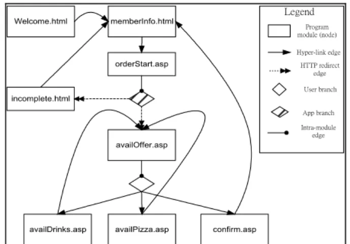
A Web application consists of a set of programming modules which are executed at the servers or the browser. To build the control flow graph for the Web application, our proposed method maps each entity in the Web application to a component of the control graph, i.e. nodes, branches, edges. The extended control graph for the Web application contains the following symbols as appeared in Figure 4: programming module (node), user branch, application branch, hyper-link edge, HTTP-redirect edge, and intra-module edge.
A node in the control flow graph represents a programming module. A programming module is usually implemented in a single file such as .html file in HTML, .cgi file in Perl, or .asp
file in ASP. There may exist a more detailed control flow graph residing in the single programming module, but it is not discussed when considering the inter-module control graph. During the mapping of control flow branch, the extended model classifies the branches into the user branch and the application brach. The user branch models that the user selects one of hyperlinks from the browsed document at browser side. The application branch models that the current programming module forwards the control to other programming modules for further processing based on the application logic.
When a programming module M generates an HTML document containing hyperlinks to modules M1, M2 and M3 for user’s
selection, node NM, NM1, NM2and NM3 are created to represent
programming module M, M1, M2 and M3 respectively in the
control flow graph. In addition, an user branch symbol UB is placed among NM, NM1, NM2and NM3. An intra-module edge is
used to associate NM and UB. Each branch alternative from UB
to NM1, NM2 and NM3 respectively is represented by one
hyper-link edge.
When a programming module M needs to transfer the control to module M1, M2, or M3 for furthur processing based on the
application logic, an intra-module link is used to connect the node for module M with an application brach symbol to represent the control transfer made by application logic. Each application branch alternative is connected by an HTTP-redirect edge. The name ‘HTTP-redirect’ comes from the technique which achieves the control transfer between Web programming modules by sending HTTP redirect command to the browser. When a module X needs to transfer control to module Y, it sends to the browser an HTTP-redirect command containing the URL referring to module Y. On receiving the URL, the browser sends a new HTTP request which invokes module Y to the server. Thus, the application’s control transfers from module X to module Y. For exapmle, a Web application which provides on-line food order services contains the following programming modules:
Ø welcome.html : It shows the usage of the on-line order system in the Web page. It contains an HTML link for the customer to link to memberInfo.asp.
Ø memberInfo.html: The module provides an HTML form for the user to fill in customer’s name, telephone number, and address to which the ordered food is sent. This HTML form is processed by the orderStart.asp as specified by “<form action=orderStart.asp method=post>”.
Ø orderStart.asp: The module judges the validity of the customer’s input, then re-directs the browser to invoke
another module availOffer.asp or incomplete.html. Namely, after the user submit the form in memberInfo.html, next screen in the browser is generated by availOffer.asp or
incomplete.html instead of orderStart.asp.
Ø incomplete.html: This module explains the reason of incomplete customer information and contains a link to
memberInfo.html for customers to refill the information.
Ø availOffer.asp: The module outputs a HTML file containing links to availDrinks.asp, availPizza.asp and confirm.asp. The first two links guide customers to order food by categories. The third link is clicked when customer completes his order.
Ø availDrinks.asp and availPizza.asp: Several items of each category are listed in the HTML forms for customers to choose. The submitted form is processed by addOrder.asp.
Ø addOrder.asp: Add the customer’s order into a temporary order list. It redirects the browser to the availOffer.asp for more order.
Ø confirm.asp: This module commits the customer’s food order by sending the order list to the database for further process. It contains a hyper-link to memberInfo.html for new order. The application finishes when no more hyper-links invocation.
Figure 3. Programming modules for an on-line food order application
The control flow graph in Figure 4 for the above application can be constructed by analyzing its programming modules. In the figure, there are two HTTP-redirect edges from orderStart.asp to two independent modules. In other programming practices where no http-redirect is applied, the application logic implemented in
availOffer.asp and incomplete.html are merged into one single
orderStart.asp. Hence, the node for orderStart.asp would contain four hyper-links memberInfo.html, availDrinks.asp,
availPizza.asp and confirm.asp. The practice can reduce the number of programming modules, hoever it still increases the difficulties of program understanding and testing. In fact, many links are not easily determined by simple analysis on the programming modules. Following subsections introduce static and dynamic analysis methods, which can obtain a control flow graph more precisely.
3.3. A Model Obtained by Static Analysis
In static analysis, the source code of the programming modules are analyzed to extract the inter-module relations. For Web applications implemented in ordinary Web application frameworks, the application logic is scattered in several files. There are two popular approaches to specify application logic. One is based on document content, it specifies application logic inside some blocks of augmented HTML files. The other is based on application logic, it specifies logic in script languages like PERL and lets the script output the desired HTML file.Welcome.html memberInfo.html
orderStart.asp
availOffer.asp
availDrinks.asp availPizza.asp confirm.asp incomplete.html User branch HTTP redirect edge Hyper-link edge Program module (node) Legend App branch Intra-module edge
Figure 4. A sample control flow graph of Web application
When constructing a model through static analysis, the application designed in the content-oriented approach can be extracted richer link information due to its format simplicity. Analyzers can extract inter-module information from the augmented HTML file (or HTML template) by extracting attributes from certain HTML tags. For example, the following fragment of an augmented HTML file can be extracted hyper-links shown in bold-italic typeface.
<a href=memberInfo.html …> … <form action=orderStart.asp …> … <frame src=leftPane.html> …
<image src=roadmap.gif usemap=#mapDef>
… <script> … WindowObject.href=”foo.html” … </script> … <map name=mapDef>
<area shape=rect ... href=site1.html> <area shape=rect ... href=site1.htm2> <area shape=rect ... href=site1.htm3> </map>
Figure 5. Hyperlinks inside a programming module
However, for the following fragment written in Microsoft ASP, it is difficult to extract the five links generated by the fragment with static analysis only. The dynamic analysis in the next subsection can help to extract the links generated dynamically.
<html> <ul> <%
for i = 1 to 5
ref = “option” & i & “.html”
Response.write(“<li> <a href=” & ref & “>” & i & “</a>” )
next %>
</ul> </html>
Figure 6. A sample .ASP file which needs dynamic
analysis on the Web server
3.4. A Model Obtained by Dynamic Analysis
The dynamic analysis on the Web application can extract the link information by driving (loading) the program modules to its interpreting engine. As mentioned above, programming modules may be executed at servers or browsers. Supporting tools may be desinged to analyze the following information:(1) The link information of the programming module after the server interpretation: For example, the ASP scripts shown in Figure 6 contains no link information at static analysis. After the supporting tool drives it into the server’s interpretation engine, five links (i.e. option1.html, option2.html, ... and option5.html) can be extracted from the interpreter’s HTML output. A server script driving tool shown in figure 7 may be provided to support the extraction.
(2) The link information of the programming module after the browser interprets the client-side scripts: For example, by drving the following JavaScript to the browser’s interpreter, two more links (i.e. site1.html and site2.html) can be obtained. It is similiar to case (1) but the difference is in the way to get the links information, as shown in figure 9.
Server Interpreted Script Server Script Intepreter Server Script Driver Control Flow Builder
1. Script Interpretation Request 2. Retrieved script
3. Interpreted sciprt. in HTML format 4. Hyper-link information
for requested scripts
application model repository
5. updated link information
Figure 7. Dynamic analysis for server interpreted scripts. <html>
<ul> <Script>
for (i=1; i<3; i++) { ref= “site” + i + “.html”
document.write(“<li> <a href=” + ref + “>” + i + “</a>” )
} </Script> </ul> </html>
Figure 8. Java Scripts for dynamic analysis on the Web browser Browser Interpreted Script Client Script Interpreter Client Script Driver Control Flow Builder
1. Script Interpretation Request 2. Retrieved script
3. Link information from client script interpreter 4. Hyper-link information
for requested scripts
application model repository
5. updated link information
Figure 9. Dynamic analysis on browser interpreted scripts.
(3) The link information generated during user interaction on the Web page: The programming module may dynamically generate hyper-link request based on user’s interaction on the Web page. For example, the augmented HTML file in Figure 10 allows the user to enter page number, say 7. After the user presses the button “Go!”, the browser generates a hyper-link page7.html and changes the browser’s content to page 7. The type of link information extraction requires a person or
automatic GUI driving tools to drive the user interface. Thus, a link monitor in Figure 11 can extract the link information.
<html> <script> function gotoPage(n) { document.location = "page" + n + ".html"; } </script> <form name=foo>
Page number to go: <input type=text
name=pageNo>
<input type=button value="Go!" onClick='gotoPage(pageNo.value);'> </form>
</html>
Figure 10. Hyper-link request generated based on user’s interaction Web Browerser Web Server Link
Monitor applicationmodel
repository Control Flow Builder 1. HTTP request 2. Intercepted hypter-link requests 3. Updated link information Intercepted HTTP requests GUI operation guide
Figure 11. Analysis on hyper-links generated by user interactions.
3.5. Generating Test Case for Web
Applications
With the application model constructed for the Web applications, test case generation techniques based on control-flow graphs, such as path testing, can be applied to test Web applications directly [8][12][13]. Two path testing strategies, statement and branch coverage, are adopted in the environment.
Practical program testing requires both the statement and branch coverage. IEEE software test standard [2] regards the statement coverage as the minimum testing requirement. The statement coverage strategy requires that the generated test cases exercise each statement in the program at least once. The branch coverage requires that the test cases exercise every branch alternative at least once. In the Web application testing, the term statement is replaced with programming module.
For example, based on the statement coverage strategy, one set of test cases generated for the sample application shown in Figure 4 are listed as the following:
TestCase# 1 2 Nodes In Path -welcome àmemberInfo àorderStart àincomplete -welcome àmemberInfo àorderStart àavailOffer àavailDrinks TestCase# 3 4 Nodes In Path -welcome àmemberInfo àorderStart àavailOffer àavailPizza -welcome àmemberInfo àorderStart àavailOffer àconfirm
If the branch coverage stragtegy is used to generate test cases, more paths are included in addition to above four paths. Paths containing edges availDrinksàavailOffer, availPizzaà
availOffer, and confirmàmemberInfo must be included to make every branch alternative exercised.
In addition to the two major strategies, real use cases from users or application specifications are good sources of test cases. Test cases from the source are more meaningful and can indicate the commonly exectued paths. For example, if a customer of the sample application orders both the drinks and pizza, the following path can be considered as a test case:
-welcomeàmemberInfoàorderStart
à availOffer à availDrinks à availOffer à availPizza à availOffer à confirm
4. A
Web
Application
Testing
Environment
An application testing environment helps to automate the testing process and integrate testing tools to support testing during the test process. [7][21] have evaluated the architectures and capabilities of application testing environments. The Web application testing environment introduced here is to provide integrated tools to support the testing requirments as mentioned in section 3.4.1. A Model Supporting Web Application
Testing
As shown in Figure 12, the Web testing tool set consists of integrated tools which support application model construction, test case composition, test case generation, and test case execution.Tools inside the tool set are controlled through the
WWW control interface, to which authorized Web browsers can connect via HTTP. The followings present our testing activities and then the corresponding tool needs.
A Web application testing project is created throught the WWW control interface. The location and related parameters of the Web applcation under testing must be provided to proceed with subsequent testing activities. The testing activities are grouped into the following three major steps: (1)application model construction (2) test case construction and composition, and (3) test case execution.
During application model construction, it extracts the inter-module control-flow graph of the Web application. The
server script analyzer fetches the programming modules of the application under testing. It performs static link analysis on the source code of these modules. It also performs dynamic link analysis on the HTML output by interpreting the source code with the WWW server. The client script analyzer performs dynamic link analysis at client side by driving the WWW browser to fetch the programming modules and interprete the client-side scripts. Plain HTML files are regarded as special scripts which contain no script codes. Application models, which are the basis for automatic test case generation, are built by server/client script analyzers mentioned above. The test repository is responsible to store application models.
Web Testing Tool Set HTTP Recorder/ Player Client Script Analyzer Test Case Composer Sever Script Analyzer Test Case Generator Test Report Generator Load Tester WWW Control Interface
Testing Case/ Appl Model Repository Test Manager Testing Report Application Under Testing HTTP traffics WWW Server Application Browser Testing Environment Controlling Brower
Figure 12. The Web Application Testing Environment
In test case construction, testing staffs prepare test cases to test the Web application. Test case construction is performed through WWW browsers which connect to the testing environment’s WWW interface. In the test case construction interface, users can browse the hierarchy and content of test cases organized by the
test case manager. To create test cases throught the composition interface, users can apply the test case recorder, invoke test case generator, or handcraft test scripts.
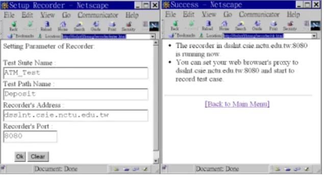
Test case recorder intercepts and records HTTP communications between Web browsers and servers to form test cases based on Web applications user’s real use-cases. To control the test case recorder’s initialization, termination, and parameters such as test case name can be done through the Web interface. The recorded test cases are inserted into the test repository through the test manager.
Figure 13. Initialize the test case recorder
Testcase generator generates test cases based on the testing strategies mentioned in section 3.6. Each generated test case contains one testing path, which consists of a sequence of URLs to visit. If the Web application whose execution path varies in accordance with the user’s input values of browser’s HTML form, the composition interface would prompt the test designers to provide proper input values which make the Web applications execute along the intended path.
Figure 14. Test case composer : Test script editing support
To specify test cases in a more flexible way the test case designer can resort to handcrafting test scripts by himself. Because the testing environment stores the outcome of test case recorders and test case generators in the test repository in the form of test scripts. Test desingers can change test cases by modifying test scripts.
4.2. The Execution of Testing Cases
The following is a sample test script which describes an error login attempt followed by a correct one. The script language supports variable assignment, loop construct, and HTTP-related primitives such as HTTPGet and HTTPPost. The expect is used to verify the redirect commands sent byWeb server to the Web browser.
#---# Test Case Description:
# user001 fails login at the first # time, and then passes at next try #---#set the base directory of the #application
set $URLBase http://dsslnt/webapp/ set $URL1 “login.html”
#set variables URL1, URL2 set $URL2 “checkLogin.asp”
#- HTTP requests begin ---HTTPGet $URL1
#login.html contains a form with two #fields user and pass
set $form1.user “user001” set $form1.pass “wrongPass” #user001 login with wrongPass HTTPPost $URL2, $form1
#expect an HTTP-redirect command, #which redirect the browser #to errorMessage.html expect “errorMessage.html”
#errorMessage.html contains a link #back to login.html,
#so follow the link to re-login HTTPGet $URL1
set $form2.user “user001” set $form2.pass “correctPass”
#user001 relogin with correctPass HTTPPost $URL2, $form2
#expect an HTTP-redirect command, #which redirect the user to main menu expect “mainMenu.html”
clear $form1 clear $form2
Figure 15. A testing script sample.
In test cases execution, the test case player interpretes designated testing scripts and sends corresponding HTTP requests. The test results of test execution are stored in the testing log of test repository, from which the test report generator summarizes testing reports.
In the Web interface of the testing environment, testing staffs can select test cases from the list for execution. They can choose to run the test cases in batch mode or in interactive mode. In the batch mode the test cases are executed in background without rendering the HTML documents. The test case validation in the mode is made by expecting some string patterns in the returned HTML documents. However, for complicated Web applications it needs human attention to validate the test cases.
Figure 16. Interactive test case execution. The right-upper frame contains tested pages.
In the interactive test case execution mode, testing staffs watch the Web pages under testing on the Web browser and control each step of the test case execution. For each test case the control panel of the test case player provides testing staffs with information about the number of Web pages to be visited, the data values to enter in HTML forms. Testing staffs lead the test case to next step or specific step by pressing the ‘next step’ button or ‘Goto N-th step’ button at the control panel.
Figure 17. Validate the test case and fill the test result
For Web pages requiring data input, testing staffs can request the test case player to fill data in the form fields on the Web page by pressing the ‘fill data’ button. The functionalities save testing staffs from manually filling testing data or locating hyperlinks to invoke on the Web page. It is especially useful when testing HTML forms with lots of data fields to fill. The test case validation is made by the testing staffs and the validation result is inserted into the test repository for generating testing report.
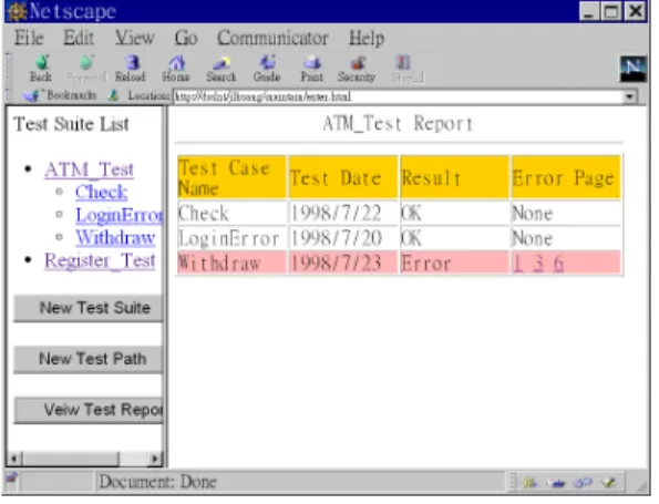
Figure 18. Generated Testing Summary
4.3. Implementation of the Environment
A prototype of the testing environment and the tool set have been developed and demonstrated. The testing center integrating tools in the tool set by several CGI programs and Java applications. The client script driver is written in JavaScript running at Web browser. The server script driver is implemented as a Java application. Hyper-link information obtained from script drivers are analyzed by PERL to form application models. Test case recorder/player are implemented as a Web proxy server with additional features.Users of the testing environment can manipulate the tools from Java Applets embedded in Web pages. The controlling interface implemented as Java Applet provides GUI for user interactions and communicates with the testing center via Java RMI [17].
5. Conclusion and Future Work
This paper models the inter-module relations of Web applications in terms of control flow graph and data flow graph. In addition, a set of testing support tools are provided to help construct application model by analyzing the programming modules statically and dynamically. Test cases of the Web application can be generated based on the application model or composed through the test case composition interface. Automatic testing tools such as test case player execute testing scripts to automate Web application test, and load tester can help to understand the performance charateristics under different load levels. The prototype of the testing tools has been implemented and integrated in the Web environment.
The future works includes: (1) constructing data flow model for the Web application to apply data-flow related test case generation strategies. (2) applying domain testing techniques to
drive the application to go through a pre-determined test path by selecting input values from proper data ranges.
Bibliography
[1] Allaire Corp., Cold Fusion, in http://www.allaire.com/products/COLDFUSION/.
[2] ANSI/IEEE Std 1008-1987, “IEEE Standard for Software Unit Testing” in Collection of ANSI/IEEE standards on software engineering, IEEE Computer Society Press, 1987.
[3] ANSI/IEEE Std 829-1983, “IEEE Standard for Software Test Documentation” in Collection of ANSI/IEEE standards on software engineering, IEEE Computer Society Press, 1987.
[4] Apache Server Project, “Module mod_include”, in http://www.apache.org/docs/ mod/mod_include.html.
[5] AutoTester Inc., AutoTester Web, in http://www.autotester.com/.
[6] Beizer B., Software Testing Techniques, 2nd ed, Van Nostrand Reinhold, 1990.
[7] Eickelmann N.S. and Richardson D.J., “An evaluation of software test environment architectures”, IEEE Proceedings of ICSE-18, p.p. 353—364, 1996.
[8] Frankl, P.G., and Weyuker, E.J., “An applicable family of data flow testing criteria”, IEEE Transactions on Software Engineering, Vol 14, p.p. 1483—1498, 1988.
[9] Fromme B., Web Software Testing – Challenges and Solutions, InterWorks ’98 Conference, 1998. Also available in http://www.interworks.org/conference/ IWorks98/sessions/sn135/paper.html
[10] Goglia, P.A., Testing Client/Server Applications, QED Publishing Group, 1993.
[11] Homer A., et al. “Professional Active Server Pages”, WROX publishing, 1997.
[12] Ntafos, S. C., “A comparison of some structural testing strategies”, IEEE Transactions on Software Engineering, Vol 14, p.p. 868—874, 1988.
[13] Rapps, S., and Weyuker, E.J., “Selecting software test data using data flow information”, IEEE Transactions on Software Engineering, Vol 11, p.p. 367—375, 1985.
[14] Rational Software, SQA Site Check, in http://www.rational.com/products/sitecheck/.
[15] Sun Microsystem, Java Servlet, in http://java.sun.com/products/java-server/servlets/
index.html.
[16] Sun Microsystem, JDBC, in http://java.sun.com/products/jdbc/index.html
[17] Sun Microsystem, Java RMI, in http://java.sun.com/products/jdk/rmi/index.html.
[18] Softbridge Inc., Web Analyst, in http://www.sbridge.com/. [19] Sun Microsystem, SunTest Suite, in
http://www.sun.com/suntest.
[20] Testing and Testing Management Tools. Available in http://www.methods-tools.com/tools/testing.html.
[21] Vogel P.A., “An Integrated General Purpose Automated Test Environment”, ACM ISSTA ’93, p.p. 61—69, 1993.