Using Soft Computing Techniques
Rudra Narayan Dash
Department Of Electrical Engineering
National Institute Of Technology, Rourkela-769008
India
Using Soft Computing Techniques
Thesis submitted in partial fulfillment
of the requirements for the degree of
Master of Technology (Research)
In
Electrical Engineering
By
Rudra Narayan Dash
Roll No. 608EE302
Under the guidance of
Dr. Susmita Das
Dr. Bidyadhar Subudhi
Department Of Electrical Engineering
National Institute Of Technology, Rourkela-769008
India
This is
motor
submit
Degree
researc
Engine
the req
embod
other d
Place: NIT Date: Des to certif
using sof
tted to th
e of Mas
ch work,
eering un
quiremen
died in th
degree
.
T, RourkelaD
N
R
Dr. epartment o NIfy that th
oft compu
he Nation
ster of Te
carried
der my su
nts for th
he thesis
Departm
Nation
Rourkela
Susmita Da of Electrical IT RourkelaCer
he thesis
uting tech
nal Instit
echnology
d out by
upervisio
e award
have not
ent of El
al Insti
a-769008
as Engineering artifica
entitled
hniques”
tute of T
y (Resear
him in
n. I belie
of maste
t been su
lectrical E
tute of
8, Orissa,
g Date
“Fault d
by Mr. R
Technolog
rch) is a
the Depa
ve that th
er of Tec
ubmitted f
Engineer
f Techn
, India.
Dr. B epartment Ndiagnosis
Rudra Na
gy, Rour
a record
artment o
he thesis f
chnology.
for the a
ring
nology,
idyadhar Su of Electrica NIT Rourkelin induc
arayan D
rkela for
of bona f
of Electr
fulfils par
The res
award of
Rourk
ubudhi al Engineerin laction
Dash
the
fide
rical
rt of
sults
any
kela
ngI take the opportunity to express my reverence to my supervisor Prof. Susmita Das and Co-Supervisor Prof. Bidyadhar Subudhi for their guidance, inspiration and innovative technical discussions during the course of this work. Their perpetual energy and enthusiasm in research had motivated others, including me. In addition, they were always accessible and willing to help their students with their research. As a result, research life became smooth and rewarding for me. Prof. S. Ghosh, Prof. G.S. Rath and Prof. P. C. Panda deserve special thanks as my thesis committee members and Chairman.
I thank all my teachers Prof. J.K. Satapathy, Prof. A.K. Panda, Prof. D. Patra, Prof. S. R. Samantaray, Prof B. Chitti Babu and Prof. K. R. Subhashini for their contribution in my studies and research work. They have been great sources of inspiration to me and I thank them from the bottom of my heart.
I would like to express my thanks to Mr. S. Swain and Mr. B. N. Sahoo for helping me for conducting my experimental work.
I would like to thank all my friends and especially my classmates for all the thoughtful and mind stimulating discussions we had, which prompted us to think beyond the obvious.
Last but not least I would like to thank my parents, who taught me the value of hard work by their own example. They rendered me enormous support being apart during the whole tenure of my stay in NIT Rourkela.
Rudra Narayan Dash
Abstract
viiiList of Tables
xList of Figures
xi
Acronyms
xvi1.
Introduction
11.1 Background 1 1.2 Different Types of Faults in an Induction Motor 2
1.2.1 Stator Faults 2 1.2.1.1 Stator Winding related Faults 3 1.2.1.2 Stator Core related Faults 4 1.2.2 Rotor related Faults 5 1.2.2.1 Rotor Winding related Faults 5 1.2.2.2 Broken Rotor Bar Fault 5 1.2.2.3 Bearing and Gearbox Faults 6 1.2.2.4 Eccentricity related Faults 6 1.3 Literature Review on Different Fault Diagnosis Techniques 7 1.3.1 Model Based Technique 7 1.3.2 Signal Processing Technique 9 1.3.3 Soft Computing Technique 11 1.4 Objectives of the Thesis 13
1.5 Motivation 14
Fault Diagnosis
2.1 Introduction 16 2.2 Experimental Setup 16
2.3 Induction Motor Parameters 18 2.3.1 No- Load Test 18 2.3.2 DC Test for Stator Resistance 20 2.3.3 Block Rotor Test 21 2.4 Induction Motor Parameters under Healthy Condition 23 2.5 Induction Motor Parameters under Stator Inter-turn Fault Condition 24 2.6 State Space Representation of a Faulty Induction Motor 25 2.7 Data Generation for Induction Motor Fault Diagnosis 27 2.8 Chapter Summary 32
3.
Fault Detection Schemes using Different Neural Network
Paradigms
333.1 Introduction 33 3.2 Proposed NNs Approach to Induction Motor Fault Diagnosis 34
3.2.1 Preparation of a Suitable Training Data Set for the NNs 35 3.2.2 Selection of a Suitable NNs Structure 36 3.2.2.1 Selection of a Suitable MLPNN Structure 36 3.2.2.2 Selection of a Suitable RNN Structure 37 3.2.2.3 Selection of a Suitable RBFNN Structure 38 3.2.3 Training Methodology of the NNs 39 3.2.3.1 Training Methodology of MLPNN 39 3.2.3.2 Training Methodology of RNN 43 3.2.3.3 Training Methodology of RBFNN 46 3.2.4 Evaluation of the Test Pattern 48 3.3 Results and Discussions 49
3.3.2 Fault Detection Performance of RNN 57 3.3.2.1 Training Results for RNN 57 3.3.2.2 Testing Results for RNN 59 3.3.3 Fault Detection Performance using RBFNN 65 3.3.3.1 Training Results for RBFNN 65 3.3.3.2 Testing Results for RBFNN 67 3.3.4 Performance Evaluation using Proposed Approaches 73 3.4 Chapter Summary 74
4.
Fault Detection Scheme using Neuro-Fuzzy Approach
754.1 Introduction 75 4.2 Brief Idea about ANFIS 76
4.2.1 ANFIS Architecture 76 4.2.2 Fuzzy Inference Systems With Simplified Fuzzy if-then Rules 79 4.3 Propose ANFIS Approach to Induction Motor Fault Detection 81 4.3.1 Preparation of a Suitable Training Data Set for the ANFIS 82 4.3.2 Selection of a Suitable ANFIS Structure 83 4.3.3 Training of the ANFIS 84 4.3.4 Testing Results for ANFIS 87 4.4 Chapter Summary 95
5.
Fault Detection Scheme using Discrete Wavelet Analysis
965.1 Introduction 96 5.2 Discrete Wavelet Transform 97
5.2.1 Motivation of using Discrete Wavelet Transform 97
5.3 DWT Based Fault Identification 101 5.3.1 Capture of the Phase Currents under Healthy and Faulty Condition 101 5.3.2 Application of the DWT 103
5.3.2.1 Selection of the Mother Wavelet 103 5.3.2.2 Specification of the Number of Decomposition Levels 103
5.4 Results and Discussions 106 5.4.1 Diagnosis of a Healthy Induction Motor 106 5.4.2 Diagnosis of a Faulty Induction Motor 108 5.5 Quantification of Degree of Severity of Fault 111 5.6 Chapter Summary 112
6.
Conclusions and suggestions for Future Work
1136.1 Summary of the Thesis Work 113 6.2 Thesis Contributions 115 6.3 Future Scope of Work 115
ABSTRACT
Induction motors are one of the commonly used electrical machines in industry because of various technical and economical reasons. These machines face various stresses during operating conditions. These stresses might lead to some modes of failures/faults. Hence condition monitoring becomes necessary in order to avoid catastrophic faults. Various fault monitoring techniques for induction motors can be broadly categorized as model based techniques, signal processing techniques, and soft computing techniques. In case of model based techniques, accurate models of the faulty machine are essentially required for achieving a good fault diagnosis. Sometimes it becomes difficult to obtain accurate models of the faulty machines and also to apply model based techniques.
Soft computing techniques provide good analysis of a faulty system even if accurate models are unavailable. Besides giving improved performance these techniques are easy to extend and modify. These can be made adaptive by the incorporation of new data or information. Multilayer perceptron neural network using back propagation algorithm have been extensively applied earlier for the detection of an inter-turn short circuit fault in the stator winding of an induction motor. This thesis extends applying other neuro-computing paradigms such as recurrent neural network (RNN), radial basis function neural network (RBFNN), and adaptive neural fuzzy inference system (ANFIS) for the detection and location of an inter-turn short circuit fault in the stator winding of an induction motor.
By using the neural networks, one can identify the particular phase of the induction motor where the inter-turn short circuit fault occurs. Subsequently, a discrete wavelet technique is exploited not only for the detection and location of an inter-turn short circuit fault but also to find out the quantification of degree of this fault in the stator winding of an induction motor. In this work, we have developed an experimental setup for the calculation of induction motor parameters under both healthy and inter-turn short circuit faulty conditions. These parameters are used to generate the phase shifts between the line currents and phase voltages under different load conditions. The
LIST OF TABLES
Table I 2-HP Induction Motor Characteristic 18 Table II Induction Motor Parameters under Healthy Condition 23 Table III Induction Motor Parameters under Inter-Turn Faulty Condition 24 Table IV Comparison between Training Errors 94 Table V Comparison between Testing Errors 94 Table VI Frequency Bands for the Wavelet Signal 104 Table VII Calculated Quantification Parameters 112
LIST OF FIGURES
1.1 Sources of Induction Motor Faults 3 1.2 Types of fault diagnosis techniques of Induction Motor 7 2.1 Cross-sectional view of 2-hp IM 17 2.2 Skewed stator with winding coils and taps 17 2.3 Schematic diagram of stator windings with taps 18 2.4 Circuit for No-Load test of an Induction Motor 19 2.5 Induction Motor equivalent circuit 19 2.6 Test circuit for a dc resistance test 20 2.7 Test circuit for block rotor test for an Induction Motor 21 2.8 Induction Motor equivalent circuit 22 2.9 Current on phase A before and after fault 27 2.10 Current on phase B before and after fault 28 2.11 Current on phase C before and after fault 28 2.12 Phase shift characteristics for fault on phase A 29 2.13 Phase shift characteristics for fault on phase B 30 2.14 Phase shift characteristics for fault on phase C 30 2.15 Simulated training input data set 31 3.1 Block diagram of the fault location procedure 34 3.2 MLPNN Architecture 36 3.3 RNN Architecture 37 3.4 RBFNN Architecture 38 3.5 Information processing in a neuron 39 3.6 A Fully Recurrent Neural Network 43 3.7 MLPNN Output for fault on phase A 49
3.10 MLPNN Error for fault on phase B 50 3.11 MLPNN Output for fault on phase C 51 3.12 MLPNN Error for fault on phase C 51 3.13 Test Output of phase A for fault on phase A 51 3.14 Test Error of phase A for fault on phase A 51 3.15 Test Output of phase B for fault on phase A 52 3.16 Test Error of phase B for fault on phase A 52 3.17 Test Output of phase C for fault on phase A 53 3.18 Test Error of phase C for fault on phase A 53 3.19 Test Output of phase A for fault on phase B 53 3.20 Test Error of phase A for fault on phase B 53 3.21 Test Output of phase B for fault on phase B 54 3.22 Test Error of phase B for fault on phase B 54 3.23 Test Output of phase C for fault on phase B 54 3.24 Test Error of phase C for fault on phase B 54 3.25 Test Output of phase A for fault on phase C 55 3.26 Test Error of phase A for fault on phase C 55 3.27 Test Output of phase B for fault on phase C 56 3.28 Test Error of phase B for fault on phase C 56 3.29 Test Output of phase C for fault on phase C 56 3.30 Test Error of phase C for fault on phase C 56 3.31 RNN Output for fault on phase A 57 3.32 RNN Error for fault on phase A 57 3.33 RNN Output for fault on phase B 58 3.34 RNN Error for fault on phase B 58 3.35 RNN Output for fault on phase C 58 3.36 RNN Error for fault on phase C 58 3.37 Test Output of phase A for fault on phase A 59 3.38 Test Error of phase A for fault on phase A 59
3.41 Test Output of phase C for fault on phase A 60 3.42 Test Error of phase C for fault on phase A 60 3.43 Test Output of phase A for fault on phase B 61 3.44 Test Error of phase A for fault on phase B 61 3.45 Test Output of phase B for fault on phase B 62 3.46 Test Error of phase B for fault on phase B 62 3.47 Test Output of phase C for fault on phase B 62 3.48 Test Error of phase C for fault on phase B 62 3.49 Test Output of phase A for fault on phase C 63 3.50 Test Error of phase A for fault on phase C 63 3.51 Test Output of phase B for fault on phase C 64 3.52 Test Error of phase B for fault on phase C 64 3.53 Test Output of phase C for fault on phase C 64 3.54 Test Error of phase C for fault on phase C 64 3.55 RBFNN Output for fault on phase A 65 3.56 RBFNN Error for fault on phase A 65 3.57 RBFNN Output for fault on phase B 66 3.58 RBFNN Error for fault on phase B 66 3.59 RBFNN Output for fault on phase C 66 3.60 RBFNN Error for fault on phase C 66 3.61 Test Output of phase A for fault on phase A 67 3.62 Test Error of phase A for fault on phase A 67 3.63 Test Output of phase B for fault on phase A 68 3.64 Test Error of phase B for fault on phase A 68 3.65 Test Output of phase C for fault on phase A 68 3.66 Test Error of phase C for fault on phase A 68 3.67 Test Output of phase A for fault on phase B 69 3.68 Test Error of phase A for fault on phase B 69 3.69 Test Output of phase B for fault on phase B 70
3.72 Test Error of phase C for fault on phase B 70 3.73 Test Output of phase A for fault on phase C 71 3.74 Test Error of phase A for fault on phase C 71 3.75 Test Output of phase B for fault on phase C 72 3.76 Test Error of phase B for fault on phase C 72 3.77 Test Output of phase C for fault on phase C 72 3.78 Test Error of phase C for fault on phase C 72 3.79 Comparison between the training performances of different NNs 73 4.1 Type 3 fuzzy reasoning 76 4.2 Equivalent ANFIS architecture 77 4.3 Commonly used fuzzy if-then rules and fuzzy reasoning mechanism 80 4.4 Block diagram of the fault location procedure 81 4.5 ANFIS fault detector 83 4.6 ANFIS Output for fault on phase A 85 4.7 ANFIS Error for fault on phase A 85 4.8 ANFIS Output for fault on phase B 85 4.9 ANFIS Error for fault on phase B 85 4.10 ANFIS Output for fault on phase C 86 4.11 ANFIS Error for fault on phase C 86 4.12 Comparison between training performance between ANFIS and RBFNN 87 4.13 Test Output of phase A for fault on phase A 88 4.14 Test Error of phase A for fault on phase A 88 4.15 Test Output of phase B for fault on phase A 89 4.16 Test Error of phase B for fault on phase A 89 4.17 Test Output of phase C for fault on phase A 89 4.18 Test Error of phase C for fault on phase A 89 4.19 Test Output of phase A for fault on phase B 90 4.20 Test Error of phase A for fault on phase B 90 4.21 Test Output of phase B for fault on phase B 91
4.24 Test Error of phase C for fault on phase B 91 4.25 Test Output of phase A for fault on phase C 92 4.26 Test Error of phase A for fault on phase C 92 4.27 Test Output of phase B for fault on phase C 93 4.28 Test Error of phase B for fault on phase C 93 4.29 Test Output of phase C for fault on phase C 93 4.30 Test Error of phase C for fault on phase C 93 5.1 Filtering Process performed by the DWT 100 5.2 Flowchart for the DWT-based diagnosis methodology 101 5.3 Stator Phase current in case of healthy condition 102 5.4 Stator A phase current in case of faulty condition 102 5.5 Stator B phase current in case of faulty condition 102 5.6 Stator C phase current in case of faulty condition 102 5.7 DWT of stator phase current of a healthy induction motor 107 5.8 DWT of stator A phase current of a faulty Induction Motor 108 5.9. DWT of stator B phase current of a faulty Induction Motor 109 5.10 DWT of stator C phase current of a faulty Induction Motor 110
• MMF: Magneto Motive Force
• EPRI: Electric Power Research Institute
• BJT: Bipolar Junction Transistor
• IGBT: Insulated Gate Bipolar Transistor
• FDP: Fault Detection and Prediction
• MIMO : Multiple-Input- Multiple-Output
• FD: Fault Detection
• OLAD: Online Approximator in Discrete Time
• EMWFA: Extension in 2-D of the Modified Winding Function Approach
• OE: Output Error
• GMM: Gaussian Mixture Model
• RPS: Reconstructed Phase Space
• MCSA: Motor Current Signature Analysis
• MLPNN: Multilayer Perceptron Neural Network
• BP: Back Propagation
• RNN: Recurrent Neural Network
• RBFNN: Radial Basis Function Neural Network
• ANFIS : Adaptive Neural Fuzzy Inference System
• WT: Wavelet Technique
• FFNN: Feed-Forward Neural Network
• MSE: Mean Square Error
• MRA: Multi-Resolution Analysis
• STFT: Short Time Fourier Transform
• CWT: Continuous Wavelet Transform
• DWT: Discrete Wavelet Transform
Chapter 1
Introduction
1.1 Background
Induction motors are most commonly used electrical machines in industry because of their low cost, reasonably small size, ruggedness, low maintenance, and operation with an easily available power supply. Although these are very reliable, they are subjected to different modes of failures / faults. These faults may be inherent to the machine itself or due to operating conditions. The inherent faults may be are due to the mechanical or electrical forces acting on the machine enclosure. If a fault is not detected or if it is allowed to develop further it may lead to a failure. A variety of machine faults have been studied in the literature [1, 2] such as winding faults, unbalanced stator and rotor parameters, broken rotor bars, eccentricity and bearing faults. Several fault identification method have been developed and been effectively applied to detect machine faults at different stages by using different machine variables, such as current, voltage, speed, efficiency, temperature and vibrations. Thus, for safety and economic considerations, it is essential to monitor the behavior of motors of different sizes such as large and small.
Traditionally maintenance procedures in industry follow two approaches as follows. The first one is to perform fixed time interval maintenance, where the engineers take advantage of slower production cycles to fully inspect all aspects of the machinery. The second is to simply respond to the plant failure as and when it happens. However, making use of today’s technology, new scientific approach was becoming possible for maintenance management. One of the key elements to this new approach is predictive maintenance through condition monitoring, which depends upon the condition of the plant. Condition monitoring is used for achieves performance of machinery, reducing consequential damage, increasing machine life, reducing spare parts inventories and reducing breakdown maintenance. An efficient condition-monitoring scheme is one that provides warning and predicts the faults at early stages. Monitoring system obtains information about the machine in the form of primary data and through the use of modern signal
processing techniques; it is possible to give vital diagnostic information to equipment operator before it catastrophically fails. The problem with this approach is that the results require constant human interpretation. The logical progression of the condition-monitoring technologies is the automation of the diagnostic process. To automate the diagnostic process, recently a number of soft computing diagnostic techniques have been proposed [3, 4, 5].
Recently soft computing techniques such as expert system, neural network, fuzzy logic, adaptive neural fuzzy inference system, genetic algorithm etc. have been employed to assist the diagnostic task to correctly interpret the fault data. These techniques have gained popularity over other conventional techniques. These are easy to extend and modify besides their improved performance. The neural network can represent any non-linear model without knowledge of its actual structure and can give result in a short time. From the early stages of developing electrical machines, researchers have been engaged in developing a method for machine analysis, protection and maintenance. The use of above technique increases the precision and accuracy of the monitoring systems. The area of condition monitoring and faults diagnostic of electrical drives is essentially related to a number of subjects, such as electrical machines, methods of monitoring, reliability and maintenance, instrumentation, signal processing and intelligent systems.
1.2 Different Types of Faults in an Induction Motor
This section presents a comprehensive description of the most common faults to be found in induction machines. The faults are classified according to their location: stator and rotor which are as shown in Fig. 1.1.
1.2.1
Stator Faults
Stator faults may be divided into two types these are as follows
1. Stator winding related faults
Fig.1.1 Sources of Induction Motor Faults
1.2.1.1 Stator Winding related Faults
According to an IEEE and Electric Power Research Institute motor reliability study [6], stator faults are mostly responsible for 37% of the failures in an induction motor. Many works have indicated that the majority of induction motor stator winding failures result from the destruction of the turn insulation. In most cases, this failure starts as a turn-to-turn (inter-turn) fault which finally grows and reaches in major ones such as coil-to-coil, phase-to-phase or phase-to-ground failures, and ultimately causing motor breakdown.
Very often Stator winding of an induction machine is subjected to stresses induced by a variety of factors, such as thermal overloads, mechanical vibrations and voltage spikes caused by adjustable frequency drives. Some of the most frequent causes of stator winding failures are as follows.
• Due to high stator core or winding temperatures
• Due to Contaminations caused by oil, moisture etc
• Due to short circuits
• Due to starting stresses
• Due to electrical discharges
• Due to leakage of cooling systems
1.2.1.2 Stator Core related Faults
Stator core problems are rare compared to stator winding problems are not usually a major concern for small machines [7]. However, the repair/rebuild process is more costly in the case of the stator core failure, since it usually requires the entire core to be replaced. Therefore, there has been interest in identifying the causes of core problems and finding ways of monitoring the core in order to detect and prevent stator core failure.
The stator cores of induction machine are built from thin insulated steel laminations with a view to minimize the eddy current losses at higher operational efficiency. In the case of medium or large machines, the core is compressed after the core laminations are stacked in order to prevent the individual lamination sheets from vibrating and to maximize the thermal conductance in the core.
The main causes of stator core failures are as follows:
• Core end-region heating resulting from axial flux in the end winding region
• Core melting caused by ground fault currents
• Lamination vibration resulting from core clamping relaxation
• Loosening of core tightening at the core end resulting from vibration during operation
• Manufacturing defects in laminations
• Inter laminar insulation failure
• Stator-rotor rubs during assembly and operation
1.2.2 Rotor related Faults
The most common rotor faults in an induction machine may be classified as:
1. Rotor winding related faults
2. Broken rotor bar fault
3. Bearing and gearbox faults
4. Eccentricity related faults
1.2.2.1 Rotor Winding related Faults
Short circuit turns in induction machine rotor windings cause operational problems such as high vibration levels; therefore early detection is essential. Normally the resistance of the windings on opposite poles is identical. The heat produced by Joule’s effect is distributed symmetrically about the rotor forging. If the inter-turn insulation is damaged, then the rotor winding become short circuited. The resistance of the damaged coil diminishes and if the poles are connected in series, less heat is generated than in the symmetrical coil on the opposite pole. The rotor body thus experiences asymmetric heating, which produces a thermal bow in the rotor body, causing vibration. The unbalanced magnetic forces on the rotor produced by the change in the magneto motive force (MMF) from the winding contribute to increased vibration [8].
1.2.2.2 Broken Rotor Bar Fault
Under normal operating conditions, large mechanical and thermal stresses are presents, especially if the machine is being continually stopped and restarted or if the machine is heavily loaded. It is well known that the rotor current during starting can be as much as ten times the normal full load current and that the effects of these large currents are represented by very large thermal stresses in the rotor circuit. The starting period is also characterized by minimal cooling and maximum mechanical forces, which over stresses the rotor bars.
The cracked bar will increase in resistance and will over heat at the crack. The bar will break completely and arcing will occur across the break. This arcing will then damage the rotor laminations around the faulted bar. The neighboring bars will carry an increased current and will
be subjected to increased stresses, eventually causing these bars to fail. Finally the broken bars may lift outwards because of centrifugal forces and could damage the stator winding [9].
1.2.2.3 Bearing and Gearbox Faults
As reported in [10] EPRI(1982), bearing faults may account for 42%-50% of all motor failures, motor bearings may cost between 3%-10% of the actual cost of the motor, but the hidden costs involved in downtime and lost production combine to make bearing failure a rather expensive abnormality [11]. Ball-bearing related defects can be categorized as outer bearing race defects, inner bearing race defects and ball defects.
Different stresses acting upon a bearing may lead to excessive audible noise, uneven running, reduced working accuracy, and the development of mechanical vibrations and as a result, increased wear. More than twenty years ago, few bearing failures were electrically induced but at the beginning of the 90’s a study by [12] showed that bearing failures are about 12 times as common in converter-fed motors as in direct on-line motors. However mechanical issues remain the major cause of bearing failure as discussed in [11].
1.2.2.3 Eccentricity related Faults
Machine eccentricity is defined as a condition of the asymmetric air-gap that exists between the stator and rotor [13]. The presence of a certain level of eccentricity is common in rotating electrical machines; some manufacturers and users specify a maximum permissible level of 5%, where as in other cases, a maximum level of 10% of the air gap length is allowed by the users [14]. However, manufacturers normally try to keep the total eccentricity level even lower in order to reduce vibration, noise and minimize unbalanced magnetic pull [15]. Since the air gap of an induction machine is considerable smaller than in other types of machines with a similar size and performance, this type of machine is more sensible to changes in the length of the air gap. There are two types of air gap eccentricity: static air gap eccentricity and dynamic air gap eccentricity. In the case of static air gap eccentricity the position of the minimal radial air gap length is fixed in space, while in the case of dynamic eccentricity the center of the rotor is not at the center of the rotation and the position of the minimum air gap rotates with the rotor. Unless
detected early, the eccentricity becomes large enough to develop high unbalanced radial forces that may cause stator-to-rotor rub, leading to a major breakdown of the machine [16].
1.3 Literature Review on Different Fault Diagnosis Techniques
Various fault monitoring techniques for induction motors reported in literature can be broadly categorized as shown in Fig. 1.2.
Fig.1.2 Types of Fault Diagnosis Techniques of Induction Motor
1.3.1 Model Based Technique
Isermann [17] has presented a novel, unified model-based fault detection and prediction (FDP) technique is developed for non linear multiple-input-multiple-output (MIMO) discrete time systems. The proposed scheme addresses both state and output faults by considering separate time profiles. The faults, which could be incipient or abrupt, are modeled using input and output signals of the system. The fault detection (FD) scheme comprises online approximator in discrete time (OLAD) with a robust adaptive term. An output residual is generated by comparing the fault detection (FD) estimator output with that of the measured system output. A fault is detected
when this output residuals exceeds a predefined threshold. The asymptotic stability of the fault detection and prediction (FDP) scheme enhances the detection and time to failure accuracy. The effectiveness of the proposed approach is demonstrated by using a fourth-order MIMO satellite system.
Arkan, Kostic-Perovic and Unsworth [18] have presented two orthogonal axis models of a three phase induction motor. From these two models first one having asymmetrical windings and the other one having inter-turn short circuits on the stator winding. The machine is modeled by using classical two axis theory, and the equations are modified to take into account the stator inter-turn faults. A state space form of the system is presented for dynamic simulations. The simulation results from the models are compared with experiment carried out on a specially wound motor with taps to allow different number of turns to be shorted. The above models have been successfully used to study the transient and steady state behavior of the induction motor with short circuited turns.
Sahraoui, Ghoggal, Zouzou, Aboubou and Razik [19] have proposed a new mathematical model of the induction motor operating under stator inter-turns short circuits. The model is based on the multiplied coupled circuit approach. The inductances calculation is performed an extension in 2-D of the modified winding function approach (EMWFA), which was able to take into account the space harmonics in addition to the effects of rotor bar skewing and to the linear rise of MMF across the slots. From the results it is shown that the inter-turn short circuit gives rise to some spectral components which appear in the current line spectrum.
Bachir, Tnani, Trigeassou and Champenois [20] have suggested a new model of squirrel cage induction motors under stator and rotor faults. First, they study an original model that takes into account the effects of inter-turn faults resulting in the shorting of one or more circuits of stator-phase winding. Then, they propose a new faulty model dedicated to broken rotor bars detection. The corresponding diagnosis procedure based on parameter estimation of the stator and rotor faulty model is proposed. The estimation technique is performed by taking into account prior information available on the safe system operating in nominal conditions. In this paper the output error (OE) identification technique is used to estimate the parameters.
1.3.2 Signal Processing Technique
Stainislaw, A.H.M sadrul Ula and Andrzej [21] have proposed a new methodology for the signature analysis of induction motors, namely the instantaneous power. In this paper in place of stator current the instantaneous power is used for the motor signature analysis for the detection of mechanical abnormalities in a drive system. The information carried by the instantaneous power is the product of the supply voltage and current is higher than that deducible from the current alone. In the power spectrum of stator current the highest magnitude will appear is -52 dB, but in case of spectrum of instantaneous power the highest magnitude appears is -47dB. From the above the instantaneous power is higher by 5dB than that of the strongest non fundamental spectral component.
Yen and Lin [22] have employed a wavelet packet for extracting useful information from vibration signals of an induction motor. Though the measured vibration signals contain non-stationary part, Fourier transform cannot provide sufficient information to detect some machine faults. The results of employing wavelet packet are used with the aid of statistical based feature selection criteria to discard the feature components containing little discriminate information. The extracted reduced dimensional feature vector is then used as the input to the neural network classifier. The results show improvement in neural network generalization capability and significant reduction in training time.
Thomson and Fenger [23] have used the current signature analysis approach to detect the induction motor faults. This approach uses the motor current signature to detect the author detects different faults such as broken rotor bars in squirrel cage induction motor, detection of shorted turns in an industrial motor. In this paper the author has taken four case studies which is used to detect the different faults in an induction motors. From the results the author have clearly demonstrate that the motor current signature analysis is a powerful technique for monitoring the health of three phase induction motors.
Kim, Parlos and Bharadwaj [24] have developed a speed sensorless fault diagnosis system for induction motors. In this paper they have used to find out both the electrical (turn to turn stator winding short circuit) and mechanical (broken rotor bars, Eccentric air gap, bearing) faults respectively. Here, they have used the combination of recurrent neural networks and signal
processing algorithms such as standard Fourier based and wavelet based techniques for detecting faults in induction motors. The motor terminal voltages and current have been used as the input to the diagnosis system. The Fourier based signal processing technique is applicable if the motor is operating under steady state and the wavelet based signal processing technique is applicable if the motor operating in transient mode.
Douglas, Pillay and Ziarani [25] have introduced a new algorithm, where they followed the least squares error minimization using the method of gradient descent in a time varying set of equations. The algorithm is used for transient motor current signature analysis using wavelets. Here the residual currents are analyzed using wavelets for the detection of broken rotor bars. The advantage of this method is that it does not required parameters such as speed or number of rotor bars. Here a high order notch filter is used to separate the fundamental frequency from the rotor bar frequencies. Once the fundamental frequency has been removed, the residual current can be examined by using discrete wavelet transform analysis. Hence Daubechies 8 wavelet is used as the mother wavelet function. From the results it is clear that the broken rotor bar can be detected using measured transient in rush current.
In [26] an online diagnosis approach has been proposed for an induction motor that uses the motor current signature analysis (MCSA) with advanced signal processing algorithms. The above proposed system was able to diagnosis of induction motors having four types of faults such as breakage of rotor bars and end rings, short circuit of stator windings, bearing cracks and air-gap eccentricity faults. The motor diagnosis using MCSA depends on the slip, so if the detected slip has an error then the result of the motor diagnosis is incorrect. Hence, to detect the correct slip, an optimal slip algorithm based on the Bayesian method of estimation. In this paper the advanced signal processing techniques such as the “Proper Sample Selection Algorithm” and “Frequency Auto Search Algorithm” are used. The Proper Sample selection Algorithm is used to determine the standard of suitable samples for the MCSA process. The Frequency Auto Search Algorithm is used to detect the abnormal harmonic frequency of 1 kHz.
Aderiano, Richard and Nabed [27] have presented an induction motor fault diagnosis method using the three phase stator current envelopes for broken rotor bars and inter-turn short circuits in stator windings. The above methods not only identifies an induction motor as healthy or faulty but also identify the severity of the fault through the identification of the number of broken bars
or the number of short circuit turns in the stator windings. The training and testing sets are generated from the three phase stator current of an induction motor at both healthy and faulty operating conditions using the Gaussian Mixture models (GMMs) of the reconstructed phase space (RPSs) transforms. The author has claimed that the proposed method can constitute a powerful tool for induction motor fault diagnosis due to its high accuracy.
Riera-Guasp [28] has presented a discrete wavelet transform based technique for detection an asymmetries in the rotor of an induction motor by using the startup current and plugging stopping current, as well as the mixed eccentricities by using the startup current. He has used the Daubechies-44 and dmeyer as the mother wavelets for the discrete wavelet transform analysis. To avoid overlapping between two adjacent frequency bands such as a high order mother wavelet has been used. The author has also found out the parameters for the quantification of the severity of the fault in case of the startup rotor asymmetry and the plugging rotor asymmetry.
1.3.3 Soft Computing Technique
Nejjari and Benbouzid [29] have used the Park’s vector patterns for detecting different types of supply faults, such as voltage imbalance and single phasing. In addition a neural network based back propagation algorithm is used to obtain the machine condition by testing the shape of the Park’s vector patterns. Two neural network based approach have been used, these are classical and decentralized. The generality of the proposed methodology has been experimentally tested and the authors claim that the results provide a satisfactory level of accuracy.
Fillippetti [30] has introduced a comprehensive study about the application of artificial intelligence in machine monitoring and fault diagnosis. Here, expert system has been used as a tool for the fault diagnosis. The authors show the validity of using neural network along with fuzzy logic for fault identification and fault severity evaluation. The paper also covers a diagnosis of the inverter system, which is used to drive the motor.
Awadallah [31] has introduced a comprehensive adaptive neuro-fuzzy inference system for identification of stator short circuits in brushless DC motors, where the diagnosis of the fault was done through two independent ANFISES, first one is used to find out the shorted turns and the second one is used to identify out the faulty phase. The inputs to the first ANFIS are the diagnostic indices to determine the number of shorted turns, while the output was taken zero
during the normal operation and integers under fault conditions. Input to the second ANFIS were the three phase identification indices and its output was an integer indicating the faulty phase. Tan and Huo [32] have suggested a generic neuro-fuzzy model based approach to the detection of rotor broken bar faults in an induction motor. In this paper the data for training the neuro-fuzzy system to model the generic static torque-speed relationship of the class of induction motors used in the practical evaluation of the fault detector. Modeling error was found by comparing the output speed of the neuro-fuzzy model and the speed which is obtained from the experimental torque-speed equation. This approach overcomes the practical limitations of model based strategies as it reduces the amount of experimental data that are needed to design the fault detector. This method is also able to identify the absence/presence of cracked rotor bars under varying load conditions.
Makarand, Zaffer, Hirallal and Ram [33] have been applied an adaptive neural fuzzy inference system for the detection of inter-turn insulation and bearing wear faults in induction motor. Here, the authors have given five inputs to the ANFIS; these are motor intakes current, speed, winding temperature, bearing temperature and the noise. The neural fuzzy architecture takes into account both ANN and fuzzy logic technology. They have used multilayer feed forward network as the ANN and sugeno type fuzzy rules as fuzzy inference systems. First they have developed both the detectors with two input parameters. Then the remaining three parameters are included. In case of the two inputs for insulation detector the training error was 0.068 and the accuracy was 94.03%, for bearing condition the training error was 0.0905 and the accuracy was 90.5%.In case of the five inputs, for insulation detector the training error was 0.001209 and the accuracy was 96.67%, for bearing condition the training error was 0.000945 and the accuracy was 98.77%. It was observed from the performance results that the five inputs ANFIS technique provides more accurate results in comparison with two input system.
Rodriguez and Arkkio [34] have used a methodology using for detection of stator winding fault in induction motor. In this paper, the stator three phase rms values of currents and the variance have been used as the input to the fuzzy logic system. The input data are generated with the motor working in different load conditions by using the FEM analysis. The fuzzy logic method was able to detect the motor condition with high accuracy for both with noise and without noise.
The drawback of the method is that a current unbalance originating from the supply source may be identified as a fault condition of the motor.
Abiyev [35] has integrated both fuzzy logic system with a wavelet neural network for identification and control of an uncertain system. In this paper he has used the gradient decent algorithm for the parameter updation. Two examples have been presented for identification and control performance studies. It has been demonstrated that the fuzzy wavelet neural networks can converge faster and is more adaptive to new data.
Bouzid [36] has suggested a neural network approach for the detection and location automatically of an inter-turn short circuit fault in the stator windings of an induction motor. In this paper they have used a feed forward multi layer perceptron neural network which is trained by the back propagation technique. The phase shift between the phase voltage and line current of an induction motor is used as the input to the neural network. The desired output is set to either ‘one’ or ‘zero’. If a short circuit is detected and located on one of the three phases, the corresponding neural network output is set to ‘one’; otherwise, it is ‘zero’.
1.4 Objectives of the Thesis
The objectives of the thesis are as follows
• To develop an experimental setup for the generation of induction motor parameters under
both healthy and inter-turn fault condition.
• To emulate the phase currents for both healthy and inter-turn fault condition and find out
their behavior.
• To find out the phase shifts under different load conditions which are used as the input
for the soft computing techniques.
• To apply different soft computing techniques such as MLPNN, RNN, RBFNN, and
• To propose discrete wavelets transform approach to detect and locate stator inter-turn short circuit fault together with identification of the severity of this fault in the stator winding of an induction motor.
1.5 Motivation
Maintenance of induction motors is one of the serious problems faced by many industries and utilities. According to Electric Power Research Institute motor reliable study [6], stator faults are responsible for 37% of the induction motor failures. According to Neale [37], the purchasing and installation costs of the equipments usually cost less than half of the total expenditure over the life of the machine for maintenance. According to Wowk [38], maintenance expenditure
typically presents 15 to 40٪of the total cost and it can be up to 80٪ of the total cost.
Having reviewed most of the techniques for fault diagnosis of an induction machine it is seen that accurate models of the faulty machine and model based techniques are essentially required for achieving a good fault diagnosis. Sometimes it becomes difficult to obtain accurate models of the faulty machine and also in applying model based techniques. On the other hand, soft computing approaches such as neural networks, fuzzy logic technique, wavelet techniques provide good analysis of a system even of accurate models are unavailable. Further Multilayer perceptron (MLP) architecture using Back Propagation (BP) algorithm has been extensively applied earlier for fault detection of machines [39]. This thesis extends the other Neuro-Computing paradigms such as Recurrent Neural Network (RNN), Radial Basis Function Neural Network (RBFNN) to the detection and location of an inter-turn short circuit fault in the stator winding of an induction motor. Adaptive neural fuzzy inference system (ANFIS) has been employed for a single phase induction motor to the detection and location of an inter-turn short circuit fault [33]. The results of the fault diagnosis using this technique are good. Thus, it gave a motivation in extending the ANFIS approach to fault detection of a three phase induction motor. By using neural networks, one can identify the particular phase of the induction motor where the fault occurs from the neural network output. Subsequently, a discrete wavelet technique is exploited not only to the detection and location of an inter-turn short circuit fault but also we can know the severity of such faults in the stator winding of an induction motor.
1.6 Thesis Organization
The contents are divided in 6 chapters. Besides this introductory chapter, the following chapters are presented.
Chapter–2 illustrates an experimental set up for the calculation of induction motor parameters both under healthy and stator inter-turn short circuit faulty condition. These induction motor parameters are used to generate the induction motor phase currents and the phase angle between the line currents and phase voltages under both healthy and faulty condition.
Chapter–3 deals with different neural network techniques such as MLPNN, RNN and RBFNN for the detection of stator inter-turn short circuit fault of an induction motor. Here we have used the three phase shifts between the line currents and phase voltages of an induction motor as inputs to above all the techniques. Then we have compared both training and testing errors of the above techniques.
Chapter–4 describes the adaptive neural fuzzy inference system (ANFIS) technique for detection of the stator inter-turn short circuit fault of an induction motor. Here also we have used the three phase shifts between the line currents and phase voltages of an induction motor as inputs to the above techniques. Lastly we have compared the performance of ANFIS with the RBFNN technique.
Chapter–5 presents the wavelet technique for the detection of stator inter-turn short circuit fault of an induction motor. In this technique the motor phase currents are used as the sampling signal for diagnosis. This chapter also describes the quantification of the degree of severity of such fault.
Chapter–6 concludes the thesis and gives some suggestions for future work.
Chapter 2
Experimental Setup and Data Generation for
Induction Motor Fault Diagnosis
2.1 Introduction
Stator winding faults are one of the most important causes of faults in induction motors. Such faults are caused by several types of stress such as thermal, mechanical, electrical and environmental acting on the insulation system. All these stresses interact with each other in such a way that to degrade in the insulation system. Different types of stator faults [40] can develop under such stresses. From which inter-turn short circuit fault is one of the most common types of stator fault [41-43]. In most cases, the inter-turn short circuit fault progresses to a coil to coil, phase to phase, or phase to ground fault, causing the final breakdown of the motor.
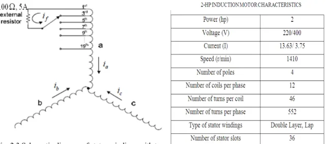
This chapter presents an experimental set up for the calculation of induction motor parameters such as stator resistance, rotor resistance, stator inductance, rotor inductance, and magnetizing inductance both under healthy and stator inter-turn short circuit fault conditions. For this experimental set up, we have used a 2-hp squirrel cage induction motor. These parameters which are calculated from the experimental set up are used in a model [36] to generate the current in the different phases and the phase shift between the line currents and phase voltages of an induction motor under both healthy and stator inter-turn fault conditions.
2.2 Experimental Setup
The experimental set up is developed by reconfiguring of an existing induction motor rated at 2-hp. The advantage of using a 2-hp induction motor is that we can limit the short circuit loop current simply by using a variable external resistor. In case of large machines these short circuit loop currents are very large as compared to the rated current. So for this reason we have taken a 2-hp induction motor.
The stato pole per inherent geometri slot pitch The stato span of 1 Fig. 2.1 Cr In order prepared The taps and endin The num inside th phases si limit the the shor reconfigu or core consi phase. A cr cogging tor ic configurat h by 300 elec or phase win 500 electrical ross-sectional v to emulate s with taps f were solder ng with the“ mber of taps t he motor hou
ince the stat short-circui rted portion urable induc ists of 36 slo ross-section rque effects tions and the ctrical. The ndings are d l.
view of 2-hp IM stator inter-t for the purp red sequenti “end” point to be soldere using. These tor faults are it loop curre n of the w tion motor a
ots. There are al view of t due to the e effects of skewed stat ouble-layere M turn short-ci ose of “exp ially every tw of turn #45 o ed in the win e taps are s e likely to oc ent; a variabl winding turn are given in T e 9 slots per the motor is space harm winding lay tor including ed, lap-conn Fig. 2.2 Skew rcuit faults, perimental m wo turns, be of the machi ndings is res pecially add ccur closest le external r ns (Fig. 2.3 Table I. r pole (for a s depicted in monics arisin youts the sta g its winding nected with s
wed stator with the motor h mimicking” o eginning wit ine as shown stricted by th ded at the m to the term resistor is co 3). The de 4-pole moto n Fig. 2.1. ng from the ator core wa g coils is sh short pitched winding coils has a phase w of incipient h the “start” n in Fig. 2.3. he amount o motor termin inal end of t onnected bet sign charac
or) and 3 slot To minimiz magnetic c s skewed by hown in Fig d coils, each and taps winding that inter-turn f ” point of tur .
of space avai nal of one o the winding tween the ta cteristics of ts per ze the ircuit y one . 2.2. h of a t was faults. rn #1 ilable of the gs. To aps of f this
Fig. 2.3 Schematic diagram of stator windings with taps
2.3 Induction Motor Parameters
The equivalent circuit of an Induction Machine is very useful for determining its response to change in load. However, if a model is to be used for a real machine, it is necessary to determine the machine parameters. This information may be found by performing a series of tests such as No-load test, DC test and short-circuit tests on induction motor.
2.3.1 No- Load Test
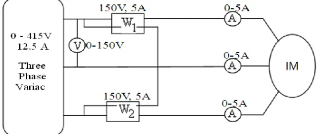
The no-load test on an induction motor is conducted to measure the rotational losses of the motor to obtain information about the magnetizing current. The test circuit for this test is shown in Fig.
2.4. A voltmeter and three ammeters are connected to an induction motor. Wattmeters W1 and
W2 are connected to an induction motor. As the motor is not connected to any load, all the power
supplies to the motor are converted to the friction and windage losses. The equivalent circuit of the motor is shown in Fig. 2.5. With a small slip, the resistance corresponding to its power converted,
s s) (1 RS −
is much larger than the resistance corresponding to the rotor copper losses
Rr and much larger than the rotor reactance Xr.
At no-load conditions, the input power measured by the meters W1 and W2 gives the losses
occurs in the motor. The rotor copper losses are negligible because the current I2 is extremely
small so may be neglected. The stator copper losses are given by
S 2 1
SCL 3I R
Fig.2.4 Circuit for No-Load test of an Induction Motor
Fig.2.5 Induction Motor equivalent circuit Hence the input power must equal
W & F Core SCL in P P P P = + + rot S 2 1R P 3I + =
where Prot is the rotational losses of the motor, given by
W & F Core rot P P P = +
Thus, given the input power to the motor, the rotational losses of the machine may be determined.
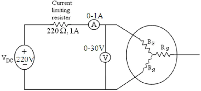
2.3.2 DC Test for Stator Resistance
The rotor resistance Rr plays an extremely critical role in the operation of an induction motor. A
standard motor test called the block rotor test can be used to determine the total motor circuit
resistance. However, this test gives only the total resistance. To find the rotor resistance Rr
accurately, it is necessary to know Rs so that it can be subtracted from the total value of
resistance.
There is a test for Rs independent of Rr. This test is called the dc test. Basically, a dc voltage is
applied to the stator windings of an induction motor. Because the current is dc, there is no induced voltage in the rotor circuit and no resulting current flow. Therefore, the only quantity limiting current flow in the motor is the stator resistance, and that resistance can be determined.
Fig.2.6 Test circuit for a dc resistance test
The basic circuit for conducting the dc test is shown in Fig.2.6, which shows a dc power supply connected to two of the three terminals of a Y-connected induction motor. To perform the test, current in the stator windings is adjusted to its rated value, and the voltage between the terminals is measured. The current in the stator windings is adjusted to the rated value in an attempt to heat the windings to the same temperature they would have during normal operation.
Fig. 2.6 shows the flow of current through two of the windings of the induction motor. The total
DC DC S I V 2R = DC DC S 2I V R =
With this value of RS the stator copper losses at no load may be determined.
2.3.3 Block Rotor Test
The third test that can be performed on an induction motor to determine its circuit parameters is the block-rotor or short-circuit test. In this test, the rotor is blocked so that it cannot move. A voltage is applied to the motor terminals, and the resulting voltage, current, and power is measured.
Fig. 2.7 shows the connections for the block rotor test. To perform the block rotor test, an ac voltage (approximately 100V) is applied to the stator, and the current flow is adjusted to a value approximately full-load value. When the current reaches the full-load value, the voltage, current, and power flowing into the motor are measured. The equivalent circuit for this test is shown in
Fig. 2.8. Since the rotor is static, the slip s = 1, and so the rotor resistance Rr/s is just equal to Rr
which is quite a small value. Since Rr and Xr are small values, almost all the input current will
flow through them, instead of through the much larger magnetizing reactance XM. Therefore, the
circuit under these conditions looks like a series combination of XS, RS, Xr, and Rr.
There is one problem with this test. i.e. in normal operation, the stator frequency is the line frequency of the power system. At starting condition the rotor is also at line frequency. However, at normal operating conditions, the slip of the motor is only 2 to 4 percent, and the resulting rotor frequency is in the range of 1 to 3 Hz. This creates a problem in that the line frequency does not represent the normal operating conditions of the rotor. Since effective resistance is a function of frequency.
Fig.2.8 Induction Motor equivalent circuit
After a test voltage and frequency have been set up, the current flow in the motor is quickly adjusted to about the rated value, and the input power, voltage, and current measured before the rotor can heat up too much. The input power to the to the motor is given by
cosθ
I V 3
P= L L
where VL, IL and cos θ are Line voltage, Line current and power factor respectively.
Hence, for blocked-rotor test power factor can be found by
L T in I V 3 p θ cos PF= =
The magnitude of the total impedance in the motor circuit at this time is
L T LR I 3 V Z =
and the angle of the total impedance is θ. Therefore, ' LR LR jX R + = LR Z sinθ jZ cosθ ZLR + LR =
The rotor resistance RLR is equal to
RLR = R1 + R2
While the rotor reactance is equal to
' 2 ' 1 ' LR X X X = + Where X and 1' ' 2
X are the stator and rotor reactances at the test frequency, respectively.
The rotor resistance R2 can now be found as
R2 = RLR – R1
where R1 was determined in the dc test. The total rotor reactance referred to the stator can also be
found. Since the reactance is directly proportional to the frequency, the total equivalent reactance at the normal operating frequency can be found as
XLR = X1 + X2
2.4 Induction Motor Parameters under Healthy Condition
From the above three tests (No load test, DC test and Block rotor test) one has to find out the Induction Motor Parameters under healthy condition. These are given in table II.
Table II
Induction Motor Parameters under Healthy Condition
Sl. No Rs (ohm) Rr (ohm) Ls (Henry) Lr (Henry) Lm (Henry)
2.5 Induction Motor Parameters under Stator Inter-Turn Fault
Condition
From the above three tests (No load test, DC test and Block rotor test) we have found out the Induction Motor Parameters have been calculated when a stator inter-turn fault occurs in the phase-A of an induction motor. These are given in table III.
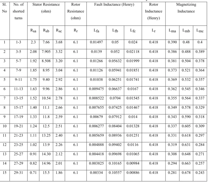
Table III
Induction Motor Parameters under Inter-Turn Faulty Condition Sl. No No. of shorted turns Stator Resistance (ohm) Rotor Resistance (ohm)
Fault Inductance (Henry) Rotor Inductance
(Henry)
Magnetizing Inductance
Rsa Rsb Rsc Rr Lfa Lfb Lfc Lr Lma Lmb Lmc
1 1-3 2.3 7.66 3.68 6.1 0.01497 0.05 0.024 0.418 0.390 0.48 0.4 2 3-5 2.08 7.905 3.32 6.1 0.0139 0.052 0.02118 0.418 0.386 0.488 0.389 3 5-7 1.92 8.508 3.20 6.1 0.01266 0.05632 0.01999 0.418 0.381 0.504 0.378 4 7-9 1.85 8.95 3.04 6.1 0.01126 0.05941 0.01851 0.418 0.373 0.521 0.364 5 9-11 1.75 9.40 2.92 6.1 0.01038 0.06251 0.01741 0.418 0.369 0.532 0.357 6 11-13 1.63 9.96 2.86 6.1 0.009475 0.06637 0.0167 0.418 0.362 0.545 0.346 7 13-15 1.52 10.54 2.78 6.1 0.008522 0.0704 0.01545 0.418 0.355 0.564 0.337 8 15-17 1.40 11.1 2.66 6.1 0.007655 0.07425 0.01467 0.418 0.349 0.578 0.329 9 17-19 1.33 11.8 2.59 6.1 0.00679 0.07912 0.014 0.418 0.343 0.590 0.318 10 19-21 1.24 12.5 2.51 6.1 0.006277 0.08404 0.01328 0.418 0.337 0.605 0.309 11 21-23 1.11 13.25 2.40 6.1 0.005659 0.08936 0.01251 0.418 0.331 0.618 0.297 12 23-25 1.02 13.9 2.26 6.1 0.004888 0.09402 0.0116 0.418 0.319 0.631 0.284 13 25-27 0.91 14.30 2.12 6.1 0.004418 0.09698 0.01065 0.418 0.308 0.648 0.271 14 27-29 0.82 14.96 2.01 6.1 0.003825 0.10165 0.00984 0.418 0.294 0.663 0.257 15 29-31 0.71 15.5 1.86 6.1 0.00334 0.10557 0.00886 0.418 0.281 0.678 0.243
As we know that under normal operation and balanced conditions, the three phase parameters of an induction motor are same as shown in the table II. When a stator inter-turn fault will occur in an induction motor the three phase parameters are different for different phases.
2.6
State Space Representation of a Faulty Induction Motor
The model in [36] is used here to generate both healthy and faulty currents of a three phase induction motor. In faulty condition, this model can be characterized by two modes such as common mode and differential mode. The common mode refers to the dynamic modes in healthy operation of the machine whereas the differential mode refers to the faulty operation. The model of the differential mode introduces two parameters defining the faults in the stator. These are as follows
(i) θcck, (location parameter): is the angle between the inter turn short circuit stator winding
and the first stator phase axis. This parameter can take only three values 0, 2π/3, 4π/3,
corresponding to the short circuit on the phase as, bs, cs respectively.
(ii)
λ
cck, (detection parameter): is the ratio between the numbers of inter-turn short circuitwindings and the total number of turns in the healthy phase. These parameters are to quantify the unbalance.
phase healthy in turns -inter of number Total ndings circuit wi short turns -inter of Number λcck =
The state space representation of a faulty induction motor is given by BU AX X& = + DU CX Y= + where T qr dr qs dsi ] [i X= ϕ ϕ T qs dsV ] [V U=
⎥ ⎥ ⎥ ⎥ ⎥ ⎥ ⎥ ⎥ ⎥ ⎦ ⎤ ⎢ ⎢ ⎢ ⎢ ⎢ ⎢ ⎢ ⎢ ⎢ ⎣ ⎡ − − − + − − + − = m r r m r r f m r f f r s f f m r f r s L R 0 R 0 0 L R 0 R L L R L ω L R R ω L ω L L R ω L R R A T f f 0 0 L 1 0 0 0 0 L 1 B ⎥ ⎥ ⎥ ⎥ ⎦ ⎤ ⎢ ⎢ ⎢ ⎢ ⎣ ⎡ = ⎥⎦ ⎤ ⎢ ⎣ ⎡ = 0 0 1 0 0 0 0 1 C ⎥ ⎦ ⎤ ⎢ ⎣ ⎡ − =
∑
= ) ( ) ( ) ( 3 2 3 1 θ θ θ λ P Q p R D cck k cck s ⎥ ⎦ ⎤ ⎢ ⎣ ⎡ = 2 cck cck cck cck cck 2 cck cck ) sin(θ ) )sin(θ cos(θ ) )sin(θ cos(θ ) cos(θ Q ⎥⎦ ⎤ ⎢ ⎣ ⎡ − = ) cos( ) sin( ) sin( ) cos( ) ( θ θ θ θ θ P qs dsi
i
,
: dq stator current components;qr dr
φ
φ
,
: dq rotor flux linkage;qs ds V V , : dq stator voltage; θ : Electrical angle; dt dθ ω =
Rs, Lf, Rr, and Lm are the stator resistance, global leakage inductance referred to the stator, rotor resistance, and magnetizing inductance, respectively.
2.7 Data Generation for Induction Motor Fault Diagnosis
Under normal operation and balanced conditions, phase voltages and line currents equal in
magnitude and shifted by 1200 electrical due to the induction motor parameters. However, under
faulty operation, the phase currents are unequal and also their phase shifts. The different phase currents of the induction motor under both before and after the inter-turn short circuit fault have been investigated through simulation study using MATLAB software.
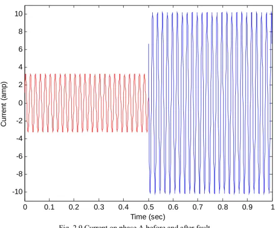
Fig. 2.9 Current on phase A before and after fault
Fig. 2.9 shows the profiles of the simulated current on phase A before and after fault condition with no load torque. When a stator inter-turn fault will occur on phase A of an induction motor introduced at 0.5 Sec, the current in that phase rises to its peak value.
0 0.1 0.2 0.3 0.4 0.5 0.6 0.7 0.8 0.9 1 -10 -8 -6 -4 -2 0 2 4 6 8 10 Time (sec) C u rre n t (a m p )
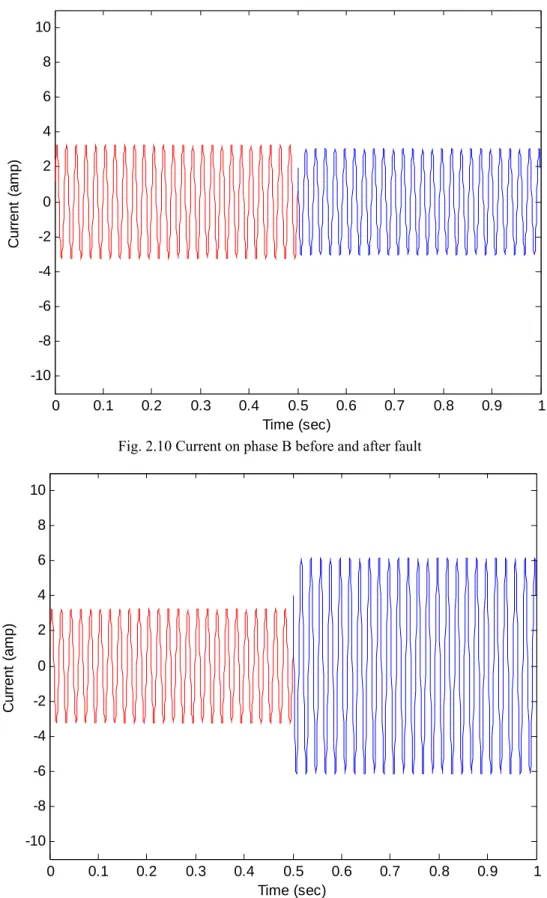
Fig. 2.10 Current on phase B before and after fault
Fig. 2.11 Current on phase C before and after fault
0 0.1 0.2 0.3 0.4 0.5 0.6 0.7 0.8 0.9 1 -10 -8 -6 -4 -2 0 2 4 6 8 10 Time (sec) C u rre n t (a m p ) 0 0.1 0.2 0.3 0.4 0.5 0.6 0.7 0.8 0.9 1 -10 -8 -6 -4 -2 0 2 4 6 8 10 Time (sec) Cu rre n t (a m p )
Fig. 2.10 indicates the profiles of the simulated current on phase B before and after fault condition with no load torque. When a stator inter-turn fault will occur on phase A of an induction motor introduced at 0.5 sec, the current in phase B is less influenced.
Fig. 2.11 illustrates the profiles of the simulated current on phase C before and after fault condition with no load torque. When a stator inter-turn fault will occur on phase A of an induction motor introduced at 0.5 sec, the current in phase C has smaller influence compared to phase A. From Figs. 2.9, 2.10 and 2.11 we can observe that, when a fault occurred in one of the three phases, the current appears particularly in the corresponding phase increases to its peak value compared with other phases. Thus, it is clear that an inter-turn short circuit fault affects the stator current of the faulty phase in peak value where the other stator phase currents have smaller influences.
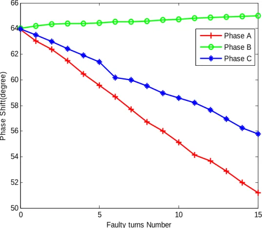
Fig. 2.12 Phase shift characteristics for fault on phase A
0 5 10 15 50 52 54 56 58 60 62 64 66
Faulty turns Number
P has e S h if t( degr ee) Phase A Phase B Phase C
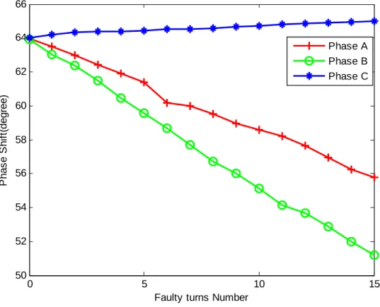
Fig. 2.13 Phase shift characteristics for fault on phase B
Fig. 2.14 Phase shift characteristics for fault on phase C
0 5 10 15 50 52 54 56 58 60 62 64 66
Faulty turns Number
P has e S h if t( d egre e ) Phase A Phase B Phase C 0 5 10 15 50 52 54 56 58 60 62 64 66
Faulty turns Number
P h as e S h if t( d e g ree ) Phase A Phase B Phase C
Effect of occurrence on stator inter-turn short circuit fault on the phase shift, can be analyzed from Figs. 2.12, 2.13, and 2.14. The characteristics of the phase shifts under a load torque of 3 N-m, as function of the faulty turn number in the case of stator inter-turn short circuit fault on the phases A, phase B, and phase C as shown in Figs. 2.12, 2.13, and 2.14 respectively. As the number of short circuit turn changes, the induction motor parameters such as stator resistance
(Rs), leakage inductance (Lf), and magnetizing inductance (Lm) also changes. It can be also noted
that, in the case of a stator fault on one of the three phases, the smallest value of the three-phase shifts is the phase where the fault has occurred.
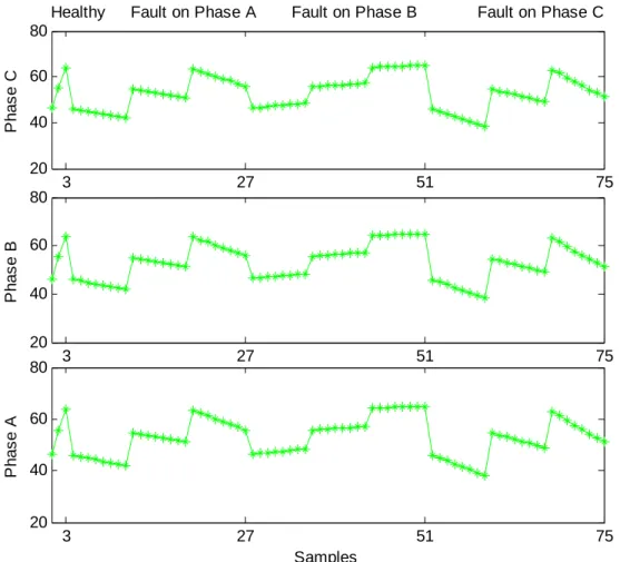
Fig. 2.15 Simulated training input data set
The input data are collected through simulations by Matlab. The data collected above will be useful in subsequent chapters for studying stator inter-turn fault conditions. To achieve the location of the induction motor faulty phase, the training data should represent the complete range of the operating conditions, which contain all possible fault occurrences and even the healthy cases. 3 27 51 75 20 40 60 80 Ph a s e C
Healthy Fault on Phase A Fault on Phase B Fault on Phase C
3 27 51 75 20 40 60 80 Ph a s e B 3 27 51 75 20 40 60 80 Samples Ph a s e A
For this purpose, the input data set, which is shown in Fig. 2.15 are composed by a successive range of several examples in different operating conditions of the induction motor. All these
examples are used in the subsequent chapters under three load torques (
τ
1 = 3 N-m,τ
2=
5 N-m,τ
3=
7 N-m) and represent the following different operating cases of the induction motor: healthy(three points) and fault of an odd number of shorted turns (1, 3, 5, 7, 9, 11, 13, and 15) on each
stator phase [24 (8 × 3) points]. Thus, a total of 75(24 × 3 + 3) training samples has been
collected and will be useful in subsequent chapters for studying stator inter-turn fault conditions.
2.8 Chapter Summary
This chapter presents an experimental setup for the generation of induction motor parameters such as stator resistance, rotor resistance, stator inductance, rotor inductance, and magnetizing inductance both under healthy and stator inter-turn short circuit fault conditions. For the generation of those parameters, we have conducted several tests (no-load test, DC test, and block rotor test) under both healthy and shorting the stator winding for every two turns sequentially, beginning with the start point of turn ‘1’ and ending with the end point of turn ‘45’ of the induction motor. A variable resistor is connected between the taps of the shorted portion of the winding turns to limit the circular loop current. Those induction motor parameters are used in the model equation [36] to generate the currents in the different phases under both conditions. By using the model equation, the data (phase shifts between the line currents and phase voltages)
have been generated under both conditions at different load torques i.e
τ
1 = 3 N-m,τ
2=
5 N-m,τ
3=
7 N-m. These generated data have been incorporated for studying stator inter-turn faultconditions which is presented in the subsequent chapters.