Development of Hand-cleaning Service-oriented
Autonomous Navigation Robot
Chia-Long Chan and Hsin-Han
Chiang
Dept. Electrical Engineering Fu Jen Catholic University New Taipei City, Taiwan, ROC.
Yen-Lin Chen and Geng-Yen Chen
Dept. Computer Science and Information Engineering National Taipei University of
Technology Taipei, Taiwan, ROC. [email protected]
Tsu-Tian Lee
Dept. Electrical Engineering Chung Yuan Christian University
Taoyuan, Taiwan, ROC. [email protected]
Abstract—This paper proposes the development of an autonomous navigation robot with hand-cleaning service in indoor environments. To navigate in unknown environments and provide service, the robot is with several intelligent behaviors including wall-following, obstacle avoidance, autonomous navigation, and human detection. A laser-sensor-based approach is used in the wall-following and obstacle avoidance behavior controllers. A preliminary map-matching algorithm is applied in the localization strategy of autonomous navigation in which the robot can acquire the current location and then move toward to the target position. In this study a hand-cleaning mechanism is embedded into the robot and the service will activate while a human is recognized within the designated range. The overall robotic system is carried out using a two-wheeled driving mobile robot with LabVIEW as an integration tool. The experimental results demonstrate the practicable application of the proposed approach.
Keywords-Wall-following, obstacle avoidance, mobile robot localization, navigation control, service robots.
I. INTRODUCTION
In recent years, service-oriented robotics has become the area of robotics with the strongest predicted growth. It promptly raises the trend toward developing a new generation of robots capable of operating in human-centered environments, interacting with people, and participating and helping them in their daily life. Such robotic systems need to be capable of learning to use their embodiment to communicate and to react to their users in a social and engaging way. To achieve this objective, service robotics is currently some of the most fascinating research fields of mobile robotics. Nevertheless, the development of human-robot interaction for assistive applications is still in its infancy. Service robot can be used in many indoor applications such as home environments and public areas including hospitals, markets, and hotels. A service robot has to be aware its presence and concentrate on its attention on humans. Therefore, it requires that the robot has an intelligent navigation system especially in unknown and changing environments, and active component for interacting with humans and providing the designed service task.
Mobile robot navigation is an essential issue in artificial intelligence of robotics. The robot should be capable of sensing its environment, interpreting the sensed information as the
knowledge of its current location and the environmental status, planning a trajectory from an initial position to a target, and controlling the robot motion and speed to reach target or move around the specified area. So far neural and fuzzy techniques have become the matured and well suited for controlling a robot. An experimental neuro-fuzzy controller with a hierarchy behavior for infrared sensor-based mobile robot is proposed for mobile navigation in indoor environments [1]. In [2], a fuzzy controller with two learning algorithms based on neural network technique is proposed for reactive navigation of mobile robots. Instead of collecting the precise training data for supervised learning in neural fuzzy systems, reinforcement learning ant optimization is developed for the mobile robot wall-following controller [3]. In this approach, no supervisor is required to plan a precise moving path or provide robot input-output training pairs. The antecedent and consequent parts of fuzzy rules are generated using online aligned interval type-2 fuzzy clustering and Q-value aided ant colony optimization, respectively. A hierarchical fuzzy behavior control strategy is proposed in [4]. The robot can accomplish its intended task in reaching its target avoiding any collisions for static and dynamic environments. In addition to the navigation intelligence, the service robot also should have intelligence to offer the service to humans. Cleaning robot vacuum although has good specifications for domestic environments, it has no controlling functions and lacks for intelligence for interaction with humans. An overview of the progress of in developing a socially assistive home robot companion for elderly people is given in [5]. The PDA-based intelligent robot system is proposed to be integrated to a home automation system, and this robot has an intelligent functional engine for robot localization and mapping, and vision processing [6]. Due to the necessity of human tracking in the service robot, the work in [7] adopts multisensory data fusion techniques for tracking people from a mobile robot using a laser scanner and a monocular camera.
This study is developing a prototype of intelligent navigation mobile robot that aims to provide the hand-cleaning service in a public indoor area. For this purpose, the robot needs to possess the navigation functionality and the human-reactive ability. In Section II, the robot system with designed facilities is introduced. In Section III, intelligent behavior control design for navigation safety is described. In Section IV, the human 2012 IEEE International Conference on Systems, Man, and Cybernetics
Fig. 1. Mobile service robot system equipped with devices.
Fig. 3. Mobile service robot system equipped with devices.
detection strategy is presented. Finally, the conclusion and future work is given in Section V.
II. ROBOT PLATFORM AND DESIGNED FACILITIES The developed mobile service robot system is shown in Fig. 1. The robot platform is made of aluminum and acryl and with a suitable size (34-31-26 cm (width-depth-height)) and weight (5.2 kg) for an indoor environment. Two DC motors independently control two front co-axle wheels, and a third passive caster is provided for support. This robot platform has a differential steering system, and its velocity and motion direction can be controlled through adjusting the velocity of the two driven wheels, respectively. For the reactive navigation to be realized, a laser range finder (LRF) is installed on a pan-tilt unit which has two motors, so that the distance between the robot and the obstacles, steps, and human legs can be measured. A network camera is used for human face detection, as located in Fig. 1. The control system of robot system is an onboard computer which is a Core Duo 1.3 GHz with 2 GB of RAM. A touch screen is available for information display and interaction. A hand cleaner is equipped on the extended shelf, and controlled by the control system through the DAQ card.
Fig. 2. Scanning range figure of laser range finder.
The major sensor for robot protection from collision and recognizing the environmental data for autonomous navigation
is the LRF. The detected range of LRF covers a 270°
semicircular field, and the maximum distance of measurement to objects in the scanning range is 4 m, as shown in Fig. 2. The detected range is divided into three groups: front side, left side, and right side, and each group has four sub-areas. The left side and the front side laser ranges are used for wall-following and collision avoidance. The right side laser range is used while detecting human.
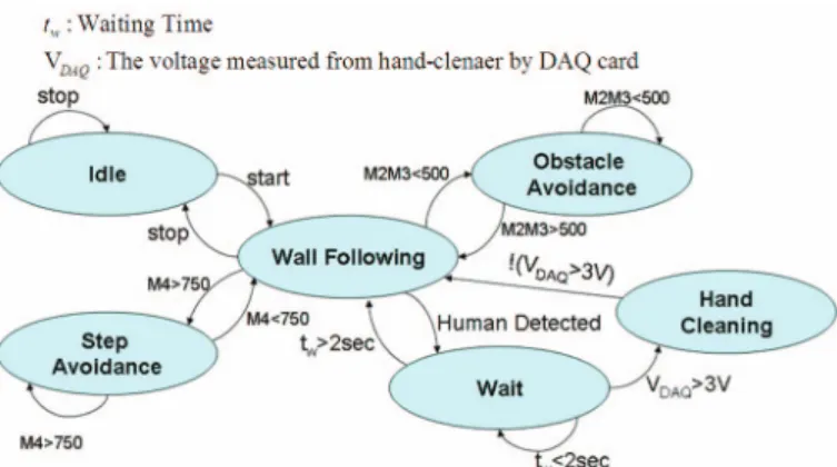
The designed state machine of the service robot system is shown in Fig. 3. Initially, the robot system executes the Wall-following behavior control, and switches to Obstacle/Step-avoidance behavior control if there is information coming from the front side (M2, M3, and M4, in Fig. 2). The hand-cleaning service will be activated while a human is recognized to be assumed to provide with the service. After service complete, the robot system continues the Wall-following behavior control. Using the information from the LRF and from the dead-reckoning strategy, the control system recalculates the moving speed and turning velocity in every control cycle (0.1 s) for the mobile robot. With the motor encoder information, the current coordinates of the robot can be estimated using a position control method so that the control system can update the robot location on the map. The primitive Wall-following behavior control is implemented by using the fuzzy controller with self-organizing learning scheme. The primitive Obstacle-avoidance
behavior control is implemented by using the adaptive neuro-fuzzy inference system (ANFIS).
III. ROBOT CONTROL SYSTEMS
The developed robot system uses an onboard computer for the robot control system. This system connects to various sensors and motor driver via USB communication interface, and it is also possible to connect with multiple devices such as mobile phone and PCs via wireless internet. Through collecting environment data, the control system calculates motion commands to right and left DC motors such that the steering can be accomplished by driving the motors at different rotation velocities. To eliminate the need of accurate modeling of robot and design complexity, control of robot using fuzzy inference systems (FIS) is adopted in our robot behavior controllers.
A. Kinematics of robot
The architecture of our robot is based on non-holonomic differential drive wheeled robot, and the kinematics of robot
Fig. 4. Kinematics of robot in X-Y global frame.
Fig. 5. Configuration of robot’s wall-following behavior.
(a)
(b)
ω
(c)
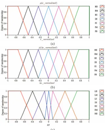
Fig. 6. (a) Membership function for of e. (b) Membership function of ¨e. (c) Membership function of Ȧ.
behavior with defined variables is illustrated in Fig. 4. Under no slipping, pure rolling, and no sliding constraints, the relations between motors and robot velocities are defined as
( r l) / 2
v r= ω ω+ (1) ( r l) /
r L
ω= ω ω− (2) where Ȧr and Ȧl indicate the angular speed of the left and right wheels, respectively; v is the moving speed of the robot; Ȧ is the rotation speed of the robot; L is the width of the robot; r is the radius of wheels. The position and orientation of the robot can be calculated with regard to robot speed in X-Y global frame. Calculation of robot current position and orientation can be determined as follows:
( 1) ( ) cos( ( )) x k+ =x k + ⋅v θ k ⋅T (3) ( 1) ( ) sin( ( )) y k+ =y k + ⋅v θ k ⋅T (4) (k 1) ( )k T θ + =θ + ⋅ω (5) From (1)-(5), the localization strategy of the robot can be easily achieved with the aid of map-matching process.
B. Wall-following behavior control
The Wall-following behavior control calculates a turning velocity that puts the robot on a trajectory parallel with the surface of the wall. In this control layer, the moving speed of robot is set to be constant. When the robot detects the wall surface, it should keep up a distance with the wall. For this
TABLE I. RULE TABLE OF THE FIS_WF. (u = ω,i = e,ǻi = ǻe)
ZE NS NM NB NB NB NB NB PS ZE NS NM NB NB NB NM PM PS ZE NS NM NB NB NS PB PM PS ZE NS NM NB ZE PB PB PM PS ZE NS NM PS PB PB PB PM PS ZE NS PM PB PB PB PB PM PS ZE PB PB PM PS ZE NS NM NB ZE NS NM NB NB NB NB NB PS ZE NS NM NB NB NB NM PM PS ZE NS NM NB NB NS PB PM PS ZE NS NM NB ZE PB PB PM PS ZE NS NM PS PB PB PB PM PS ZE NS PM PB PB PB PB PM PS ZE PB PB PM PS ZE NS NM NB i uΔi
behavior as shown in Fig. 5, the linguistic variables are chosen as follows: 3 ( ) L ( ) desired e k =d k −dw (6) ( ) ( ) ( 1) e k e k e k Δ = − − (7) where dL3 is the measured distance from the left side of the
LRF (L3, in Fig. 2), dwdesired is the desired distance between the robot and the wall. The FIS for Wall-following behavior is designed to drive the robot almost parallel to the detected wall, and it can be represented as a nonlinear mapping from e and
¨e to control input Ȧ as follows:
( )k FIS WF e k_ ( ( ), e k( ))
ω = Δ (8)
The membership functions of input linguistic variables and output linguistic variable are respectively shown in Fig. 6(a),
Fig. 7. Configuration of robot’s obstacle-avlidance behavior.
Fig. 8. Neutal fuzzy network of the Sugeno-type ANFIS. (b), and (c). The rule table is illustrated in Table I, which
follows the fuzzy sliding mode control concept with a diagonal type rule table. The sliding surface for turning velocity control is sWF = e + ¨e = 0. The defuzzification strategy is adopted by the weighted average method as
49 49 1 1 ( , ) ( , ) WF i i i i i e e e e ω μ ω μ = = =
¦
Δ¦
Δ (9)where
μ
i( )⋅ is the membership value of each rule, Ȧi is the support of each fuzzy set i, and ȦWF is the turning speed command to be assumed by the robot.C. Obstacle/step-avoidance behavior control
To guarantee a safe navigation of robot, the Obstacle-avoidance behavior control is to calculate a turning speed that drives the robot to dodge the obstacle ahead. Since real-life obstacles may have irregular shapes, it assumes that the reflection plane from the detected object surface is tangent locally to the irregular surface of the obstacle. The general case of this behavior is considered as in Fig. 7. The range data provided by the LRF (M2, M3, and M4, in Fig. 2) are fed to a Sugeno-type ANFIS, which calculates the proper turning speed
OA
ω
.The general form of a fuzzy rule for a 2-input and 1-output Sugeno-type fuzzy controller is
Rule : IF is A AND is B THEN i i j k k k k R x y m x n y o ω = + + (10) for 1,..., : 1,..., : 1,..., : i= P j= Q k= R R P Q= ×
where x and y denote the input linguistic variables,
ω
k denotesthe output for k-th rule, P and Q are the size of the fuzzy set A and B, respectively, and R is the size of the rule base. In this ANIFIS, input x is the minimum distance data from range M4 while input y is the minimum distance data from range M2 and M3. The corresponding fuzzy set for each input is {short,
medium, long}. Output
ω
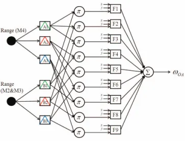
k is the turning speed for the k-thrule, and R=9 is the size of the rule base. From several experiments, the triangular membership functions are used and the size for each of the two fuzzy sets is set to 3 so that ANFIS training and testing results are best suited for our system. The generated structure of the neural fuzzy network is shown in Fig. 8.
The final output of ANFIS is implemented by using the weighted average procedure and represents the turning speed for robot collision avoidance as
1 1 1 ( ) ( ) N N N OA k k k k k k k k k W x m W y n W o
ω
= = = =¦
⋅ +¦
⋅ +¦
⋅ (11)where Wk is the normalized firing strength of rule k. With the
size N = 9 of the rule base of ANFIS, 27 consequent parameters
{m1, …, m9 , n1, …, n9 , o1 , …, o9} need to be identified. In the
training phase, a training set {x, y, ωOA} consisting of 35
measurement data points is used and the back-propagation learning algorithm is adopted. In the forward pass of ANFIS, the input membership functions are fixed and the consequent parameters associated with the output are calculated by applying the least square estimation method. The network can generate an estimate of the turning speed by using these parameters. The difference between the estimated output and that from the training set is then back-propagated in a second pass while the premise parameters associated with the input membership functions are calculated. The resulted membership functions for the range inputs are shown in Fig. 9. One can observe that, after training, the shape of these membership functions eventually become asymmetric. Due to the limited length of paper, the resulted set of consequent parameters with the Sugeno-type fuzzy rules from the training is omitted.
The range data for the step-avoidance behavior control is the left side of LRF. This is because the reference wall is in the left direction of the robot, and the measured distance value from range M4 and L1 will increase while the robot is crossing the stairway. This increasing distance error can be used in a proportional-integral-differential (PID) controller which calculates the opposite turning speed for assuring the robot of not dropping from the stairs.
IV. HUMAN DETECTION
The human detection algorithm adopts a multi-sensor data fusion approach. It assumes that the hand-cleaning service will be desired while a human is approaching close to the robot. Two different sources of information are integrated for efficient and correct human-detection performance: the first is face
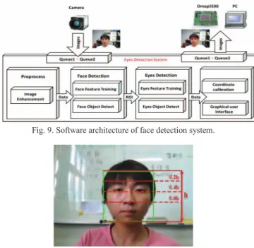
Fig. 9. Software architecture of face detection system.
Fig. 10. Face detection and from camera image and segment for eye detection.
detection based on the visual data from the camera; the other is leg detection based on the laser scans of LRF. The following sections describe the principles underlying these two detection algorithms.
A. Face detection
The face detection system in the practical usage should work in the complex environment as robustly and correctly as possible. Moreover, the efficiency of the system is the critical issue in the real-time capability. Hence, the conditions such as complex background, uneven brightness, environmental illumination, and different camera angles, which seriously affect the detection rate and the detection time should be overcome. In this study, a fast face detection which effectively deals with the non-uniform and complex environmental illumination is proposed. The software architecture of our face detection system is illustrated in Fig. 9. Each frame is with the
size of 640 × 480 pixels. This proposed framework can be
divided into the following strategies: image enhancement, reduction of uneven illumination, face detection, and eye detection. The Retinex algorithm [8] is applied to eliminate the impact of light for each input frame. The Haar-like features with AdaBoost learning algorithm [9] is used in the face detection and eye detection strategy. Note that the features of human eyes are used to increase the detection accuracy of human face, and this approach can avoid some errors due to light variations, shadows, and different skin tones in the color-based approaches. Our approach is color independent and thus not limited by the skin tone of a person.
Once the face is detected, a segmentation process from the face object is applied as shown in Fig. 10. Considering the different head posture in the frame, we propose a region of interest (ROI) with the following constraints:
Left eye region:
2 1
( , ) ( , )
5 5
L L
ROI ROI face face face face
X Y = X + W Y + H (12)
Right eye region:
1
( , ) ( , )
5
R R
ROI ROI face face face
X Y = X Y + H (13)
Two eyes region:
3 5
ROI face
W = W , HROI=Hface 3 (14)
where Wface and Hface are the width and the height of the
detected face image, respectively.
Fig. 11. Leg patterns extracted from a laser scan. B. Leg detection
The algorithm for leg detection is to extract the necessary features from the LRF. The typical patterns relative to leg postures, in most of the cases, can be well distinguished from other objects in the navigation environment. Figure 11 illustrates several examples of leg pattern scanned from the LRF, and the corresponding typical situations: legs apart, legs and legs straddle. This study adopts the similar algorithm in [7] for identifying these three leg patterns. Firstly, the readings from the right side of LRF (R1-R4, in Fig. 2) at each laser scan
are stored in an array S =[r1, …, ri , …rM], where ri is the
measured distance data on the scanning angle și and M is the
total number of readings. From this resulting array S, the three different leg patterns can be efficiently recognized by using the
vertical edge feature from the doublet { ri , ri+1 } that has a
larger distance measure | ri+1íri |. A left edge L is marked as ri > ri+1 , while a right edge R is marked as ri < ri+1 . The resulted
vertical edges are then queued into a new array E = [e1, …, en ,
…], in which each element en can be either a L or R edge. The adjacent elements can be connected as the same set if they are close and almost aligned. All the subsets are extracted from the updated list of connected edges and identified whether they are belonged to one of the three leg patterns in Fig. 11. The ordered sequences for the three leg patterns are as follows: i) the pattern for legs apart is quadruplet {L, R, L, R}; ii) the pattern for legs together is triplet {L, R, R} or {L, L, R}; iii) the pattern for legs straddle is doublet {L, R}.
The motion of the human is difficult to be estimated, and it also leads to the heavy computation load in predicting the
(a) (b)
(c) (d) Fig. 12. The snaps of service robot experimental results. (a) Human approached
the robot. (b) The robot detected human. (c) Hand-cleaning service supply. (d) The robot continued navigation.
trajectory of the human moving toward the robot. Therefore, the human detection strategy in our system uses the face detection algorithm in coordination with the leg detection algorithm, and the real-time performance can be achieved. Moreover, the distance and the direction of the detected human can be easily obtained from the midpoint of each leg pattern.
V. EXPERIMENTAL RESULTS
The whole software including the human-machine interface is implemented by using LabVIEW and runs in real time on the robot computer. The updating frequency is set to 10 Hz for the program which includes functionalities of motion control, robot localization with map-matching, and data processing.
The experiments have been conducted in our department area, and the robot system was arranged to autonomously navigate the entire corridor with the fixed moving velocity 0.5 m/s. The snaps of experimental results are shown in Fig. 12. During this mission, the performed functionalities were indicated in the developed human-machine interface, as shown in the lower left area of snaps. This interface also contained the laser scan, power display, and cleaner volume. The right side of the interface showed the real-time location of robot on the map, and the moving area of the robot can be marked out from this map editor program. The robot system usually performed the wall-following behavior, as shown in Fig. 12(a). If there were obstacles in the front or near the robot, the obstacle-avoidance behavior was activated. Once a human was detected, as shown in Fig. 12(b), the robot system stopped and waited for the instruction of hand-cleaning service. The hand cleaning service started while the human hand was detected, as shown in Fig. 12(c). After the service completed, as shown in Fig. 12(d), or the period of 2 s expired, the robot continued the navigation mission.
VI. CONCLUSION AND FUTURE WORK
This paper presents a service-oriented robot system with the capability of autonomous navigation in indoor environments. For the safety of real-time reactive navigation of a mobile robot, the Wall-following behavior control and the Obstacle-avoidance behavior control are designed based on FIS which simplifies the robot control and makes use of the expert knowledge in the form of linguistic rules. A map-matching method is applied for the robot localization so that the robot system can navigate and perform the tasks assigned to it. The human detection algorithm combines the visual face detection and the leg detection from a laser scan, and thus the hand-cleaning service can be effectively operated. The hardware implementation and experimental results have verified the performance of our proposed robotic system. The next step of out robot system focuses on an advanced positioning method and the robot simultaneous localization in real time, such as RFID-based docking guidance, so that the positioning accuracy can be further improved. In addition, the more tasks or services can be designed by adding extra sensors. The performance of applied control can also be improved with the aid of using computational intelligence methods.
ACKNOWLEDGMENT
This work was supported by the National Science Council of Republic of China under grant NSC 101-2221-E-030 -013.
REFERENCES
[1] P. Rusu, E. M. Petriu, T. E. Whalen, A. Cornell, and H. J. W. Spoelder, “Behavior-based neuro-fuzzy controller for mobile robot navigation,”
IEEE Trans. Instrumentation and Measurement, vol. 52, no. 4, pp. 1335-1340, 2003.
[2] A. Zhu and S. X. Yang, “Neurofuzzy-based approach to mobile robot navigation in unknown environments,” IEEE Trans. Systems, Man, and Cybernetics-Part C: Applications and Reviews, vol. 37, no. 4, pp. 610-621, 2007.
[3] C. F. Juang and C. H. Hsu, “Reinforcement ant optimized fuzzy controller for mobile-robot wall-following control,” IEEE Trans. Industrial Electronics, vol. 56, no. 10, pp. 3931-3940, 2009.
[4] S. A. El-Teleity, Z. B. Nossair, H. M. A. Mansour, and A. TagElDein, “Fuzzy logic control of an autonomous mobile robot,” in Proc. Int. Conf. Methods and Models in Automation and Robotics (MMAR), pp. 188-193, Aug., 2011, Egypt.
[5] H. M. Gross et al., “I’ll keep an eye on you : Home robot companion for elderly people with cognitive impairment,” in Proc. IEEE Conf. Systems, Man, and Cybernetics, pp. 2481-2488, Oct., 2011, Anchorage, Alaska. [6] H. S. Ahn, I. K. Sa, and J. Y. Choi, “PDA-based mobile robot system
with remote monitoring for home environment,” IEEE Trans. Consumer Electronics, vol. 55, no. 3, pp. 1487-1495, 2009.
[7] N. Bellotto and H. Hu, “Multisensor-based human detection and tracking for mobile service robot,” IEEE Trans. Systems, Man, and Cybernetics-Part B: Cybernetics, vol. 39, no. 1, pp. 167-181, 2009.
[8] Z. Rahman, D. Jobson, and G.Woodell, "Retinex processing for automatic image enhancement," Journal of Electronic Imaging, vol. 13, no. 1, 2004, pp. 100-110.
[9] X. Tang, Z. Ou, T. Su, H. Sunand P. Zhao, "Robust Precise Eye Location by Adaboost and SVM Techniques,"Lecture Notes in Computer Science, vol.3497, 2005, pp.93-98