MF-2041 Feed Manufacturing
Department of Grain Science and Industry
T
he goal ofon-farm feed manufactur-ing is to produce feed that meets the intended specifications, both in nutritional composition and desired medication level, and is free of contaminants. The pro-duction of quality feed will enhance animal performance and im-prove the profitability of the livestock enterprise.
A set of guidelines for processing feed, referred to as Good
Manufacturing Practices (GMPs), are designed to prevent feed contamination and provide reasonable assurance that the feed is manufactured accurately. These guidelines serve as Food and Drug Administra-tion (FDA) regulaAdministra-tions. Everyone involved in produc-ing medicated or nonmedicated feed, whether at a commercial off-farm plant or at an on-farm mill or grinder/mixer, must comply with the GMPs.
The objective of this bulletin is to provide the on-farm feed processor or nonregistered commercial mill operator with useful information pertaining to the maintenance of facilities and equipment. Correct ap-plication of these technologies will improve feed quality and operation efficiency, reduce the likelihood of feed contamination, and help ensure safe meat, milk, and eggs destined for human consumption.
Buildings and Grounds
Buildings and grounds must be constructed and maintained to prevent the contamination of feed by rodents, insects, birds, nonfeed additives (chemicals, lubricants, dangerous foreign material such as glass), and moisture.
The Code of Federal Regulations (CFR’s Title 21 Part 225.120) states that “buildings used for produc-tion of medicated feed shall provide adequate space for equipment, processing, and orderly receipt and storage of medicated feed. Areas shall include access for routine maintenance and cleaning of equipment.
Buildings and grounds shall be constructed and maintained in a manner to minimize vermin and pest infestation.”
Grain bins, hatches, lids, augers, and terrain around the bin should all prevent moisture from entering the grain and feed components. Feed ingredients must be protected from ex-cess moisture to avoid contamination by mold that can possibly pro-duce harmful toxins and reduce palatability. Rodents, birds, and insects can potentially spread disease through feces, urine, and body parts such as feathers or hair. They can cause grain to become sample grade or another type of grade reduction, and they can consume significant amounts of feed ingre-dients. Roofs, walls, doors, and floors of feed manu-facturing and storage facilities should be designed and maintained to prevent entry of these pests.
For further information pertaining to the design of bulk and bagged storage facilities for feed and feed ingredients, refer to Kansas State University Exten-sion Bulletins MF-2039 and MF-2040.
Equipment
Feed processing equipment must be designed, maintained, and operated in such a manner to ensure accuracy in ingredient proportioning and adequate processing. The CFRs (Part 225.130) for feed manu-facturing equipment state, “equipment shall be ca-pable of producing medicated feed of intended potency and purity and shall be maintained in a rea-sonably clean and orderly manner. Scales and liquid metering devices shall be accurate and of suitable size, design, construction, precision, and accuracy for their intended purposes. All equipment shall be de-signed, constructed, installed, and maintained so as to facilitate inspection and use of clean-out
procedure(s).”
Preventative
Maintenance
For Feed
Processing
Facilities and
Equipment
Fred FairchildExtension Specialist, Feed Manufacturing Grain Science and Industry
Preventive Maintenance
A plan to regularly check (or service) equipment and make necessary repairs on a scheduled basis will more than pay for itself when compared to having to do the same work in a crisis or hurried situation. As a general rule, for every dollar spent on preventive maintenance, you will save at least five dollars in subsequent expenses.
Maintenance is defined as the proper planning and action to minimize and avoid breakdowns and lost time. If an incident does occur, maintenance is a pre-pared and organized plan to return operations to nor-mal in as short a time as possible.
Maintenance can be divided into four different types.
Routine maintenance consists of servicing
equip-ment on a scheduled basis. This may consist of activi-ties such as lubrication of bearings, replacing
hammermill screens, turning or replacing hammers, checking drive V-belts, and checking oil levels in gear boxes.
Emergency maintenance entails reacting to
un-scheduled breakdowns. This maintenance must be done immediately and supersedes all other types.
Call-in maintenance usually involves an
emer-gency situation where the people required are not at hand and must be summoned from somewhere else, such as a millwright service or contractor.
Preventive maintenance consists of scheduled
inspections and making adjustments and repairs to equipment to make sure it is in proper working order. This includes the replacement (based on observed conditions or known useful life spans) of worn parts prior to failure.
The first step in developing a maintenance pro-gram entails collecting good information and organiz-ing it in a useful form. The charts in the back of this bulletin will assist the preparation of an individual-ized program. This information may be gathered under the following headings:
1. Equipment identification 2. Equipment information
3. Equipment maintenance requirements 4. Parts inventory
5. Maintenance records
Equipment Identification
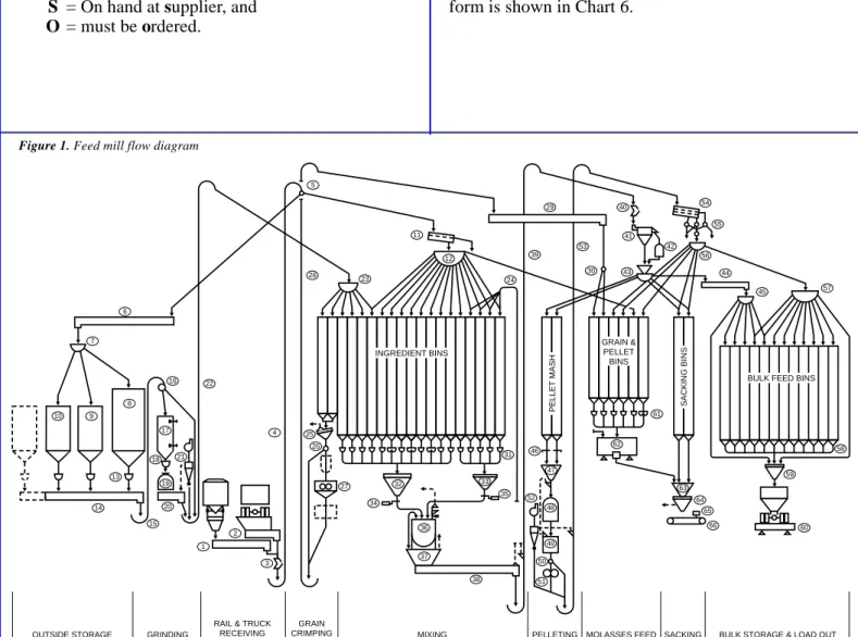
At some point, every piece of equipment in the feed mill will need maintenance of some type. In order to track the frequency of maintenance needed and its type and cost, each piece of equipment must be identified in some manner. Each piece of equip-ment should have its own identification number. An
easy way to accomplish this is to draw a flow of the entire feed milling process showing each piece of equipment along with its identification number (Fig-ure 1). It also may be desirable, in larger plants, to not only identify the equipment by number, but also by system, cost center, or physical location. An example would be A-RE-1 which says receiving conveyor #1 is located in building or area A.
Once the decision has been made on how to assign identification numbers to the equipment, it is neces-sary to prepare a master list of the equipment showing each identification number and the piece of equipment it identifies (See Chart 1).
Equipment Information
Having an equipment identification system is use-less unuse-less it is used as the key to getting and keeping information about each machine. This is most easily done by filling out an information sheet on each piece of equipment. A sample information sheet is shown in Chart 2. The information may be gathered from oper-ating manuals, purchase records, visual inspection, supplier information, or other sources. The informa-tion should include not only key part data and sizes, but also a supplier code to show where parts may be found. This code could indicate a supplier’s name, address, and phone number; or if the part is in plant inventory the code may just say “inv.” A type of sup-plier master list could be used as shown in Chart 3. Separate supplier code pages should be used for each letter of the alphabet.
Equipment Maintenance Requirements
Each manufacturer can supply recommended rou-tine maintenance procedures and schedules for the equipment they supply. This information may be found in installation and operating manuals, catalogs, or by direct contact with the supplier. Lubrication frequencies depend on operating conditions and time intervals. The equipment supplier, or your lubricant supplier, can suggest proper scheduling intervals and amounts to be used. Regular equipment checking and maintenance also will help to identify proper preven-tative maintenance scheduling and types. Emergency maintenance situations, especially as a history is de-veloped for a machine, will determine routine and preventive maintenance scheduling. A suggested maintenance schedule form is shown in Chart 4. Maintenance procedures, except for emergency main-tenance, should be tied to a calendar to ensure that required maintenance occurs as scheduled. See Chart 5 for a sample maintenance calendar.
Parts Inventory
It would be wonderful if every time an emergency maintenance situation occurred, the necessary parts were on hand and available. Unfortunately, no com-pany can afford the cash outlay it would require for the parts. A sensible approach to the parts inventory situation is to classify parts into three categories. ■Critical hard-to-get parts,
■Parts readily available from a supplier, ■Parts that allow sufficient time for securing.
Parts that are crucial or hard to get should be kept on hand or where they can be immediately obtained. Noncritical parts may be ordered from suppliers as needed.
On the Equipment Information sheets you may want to include a required availability code by each part or piece of equipment. A suggested coding might be:
I = On hand (plant inventory), S = On hand at supplier, and O = must be ordered.
The parts needed in plant inventory will be deter-mined by how often they are needed. Routine, pre-ventive, and emergency maintenance records will help identify availability requirements for parts.
Maintenance Records
As maintenance work is performed, a separate record of what was done, parts required, labor re-quired, special equipment rere-quired, and other cost items should be kept. A total cost for each mainte-nance operation should be figured and shown on the record form. This information will soon establish the maintenance cost for each machine. It will indicate potential and continuing trouble spots. It will tell how often preventive maintenance should be scheduled and what should be done to avoid emergency mainte-nance situations. It helps in making decisions about repairing or replacing equipment or even eliminating an operation or process. A simple maintenance record form is shown in Chart 6.
Figure 1. Feed mill flow diagram
6 7 10 9 8 13 14 16 17 18 19 21 20 2 1 3 4 5 28 23 11 12 24 39 29 26 25 27 32 34 36 37 38 40 41 42 43 31 54 55 53 30 56 44 45 57 59 58 63 65 66 64 62 61 46 52 47 48 49 50 51 35 22 60
BULK FEED BINS
SACKING BINS PELLET MASH GRAIN & PELLET BINS INGREDIENT BINS 33 15
OUTSIDE STORAGE GRINDING
RAIL & TRUCK
RECEIVING MIXING
GRAIN
7
Chart 1 EQUIPMENT LIST
I.D. # Description 1. _______________________________________ 2. _______________________________________ 3. _______________________________________ 4. _______________________________________ 5. _______________________________________ 6. _______________________________________ 7. _______________________________________ 8. _______________________________________ 9. _______________________________________ 10. _______________________________________ 11. _______________________________________ 12. _______________________________________ 13. _______________________________________ 14. _______________________________________ 15. _______________________________________ 16. _______________________________________ 17. _______________________________________ 18. _______________________________________ 19. _______________________________________ 20. _______________________________________ 21. _______________________________________ 22. _______________________________________ 23. _______________________________________ 24. _______________________________________ I.D. # Description 25. _______________________________________ 26. _______________________________________ 27. _______________________________________ 28. _______________________________________ 29. _______________________________________ 30. _______________________________________ 31. _______________________________________ 32. _______________________________________ 33. _______________________________________ 34. _______________________________________ 35. _______________________________________ 36. _______________________________________ 37. _______________________________________ 38. _______________________________________ 39. _______________________________________ 40. _______________________________________ 41. _______________________________________ 42. _______________________________________ 43. _______________________________________ 44. _______________________________________ 45. _______________________________________ 46. _______________________________________ 47. _______________________________________ 48. _______________________________________
Rail Receiving Conveyor Truck Receiving Conveyor Magnet
Receiving Elevator Two-Way Valve Transfer Conveyor Turnhead Distributor Corn Storage Bin Milo Storage Bin Alfalfa Storage Bin Receiving Scalper Receiving Distributor Storage Bin Feeders Grain Transfer Conveyor Grain Transfer Elevator Two-Way Valve
Surge Bin and Level Control Hammermill Feeder Hammermill
Hammermill Discharge Conveyor Hammermill Air System Grinding Elevator Grinding Distributor Pneumatic Receiving Pipes
Grain Screener (with Aspiration) Two-Way Valve
Grain Crimper Crimped Grain Elevator Transfer Conveyor Two-Way Valve
Ingredient Bin Screw Feeders Main Ingredient Scale Mineral Ingredient Scale Scale Air Gate Scale Air Gate Batch Mixer Surge Bin Surge Conveyor Mixing Elevator Magnet Mash Cleaner Overs Regrinder Mash Distributor Mash Transfer Conveyor Mash Distributor Slide Gates Surge Bin
Pellet Mill 8
Chart 2 EQUIPMENT INFORMATION
Equipment ID# ______________________________ Date Installed _______________________________ Motors (Supplier Code ______________________ ) Brand _____________________________________ HP ________________________________________ RPM ______________________________________ Volts ______________________________________ Amps ______________________________________ Input RPM _________________________________ Output RPM ________________________________ Bearings (Fan) ______________________________ Gearbox (Supplier Code _____________________ ) Brand _____________________________________ Model _____________________________________ Serial ______________________________________ Ratio ______________________________________ V-Belts ____________________________________ Chain ______________________________________ Couplings __________________________________ Misc. ______________________________________ Driven Equipment (Supplier Code _____________ ) Driven Shaft ________________________________ Driven Sheave Sprocket _______________________ Jackshaft Input Shaft _________________________ Input Sheave, Sprocket ______________________ Output Shaft ______________________________ Output Sheave, Sprocket ____________________ Final Shaft _________________________________ Final Sheave, Sprocket ________________________ Belt/Chain (Supplier Code ___________________ ) Brand _____________________________________ Type ______________________________________ Width _____________________________________ Ply/Size ____________________________________ Length _____________________________________ Splice _____________________________________ Fastener ____________________________________ Description _________________________________ Installer ____________________________________ ___________________________________________ Frame _____________________________________ Serial ______________________________________ Shaft ______________________________________ Sleeve _____________________________________ Design _____________________________________ Code ______________________________________ Tongue ____________________________________ Misc. ______________________________________ Input Shaft _________________________________ Input Sheave ________________________________ Output Shaft ________________________________ Misc. ______________________________________ Leg Belt ___________________________________ Leg Cups ___________________________________ Augers _____________________________________
Bearings (Supplier Code _____________________ ) Leg (top)_____________ (bottom) ______________ Auger (tail shaft)__________ (hangers) __________ Shafts _____________________________________ Shafts _____________________________________ Misc. Bearings ______________________________ Misc. Bearings ______________________________ Misc. Bearings ______________________________ Misc. Bearings ______________________________ Cups/Paddles (Supplier Code _________________ ) Brand _____________________________________ Style ______________________________________ Size _______________________________________ Spacing ____________________________________ Bolts ______________________________________ Punching ___________________________________ Quantity ___________________________________
Other Information Supplier Code
____________________________________________________________________________ ( ____________ ) ____________________________________________________________________________ ( ____________ ) ____________________________________________________________________________ ( ____________ ) ____________________________________________________________________________ ( ____________ ) 4 6/85 A-1 Bagdor 15 1800 230/460 — — — P-5 Dodge TXT 525 25:1 5V630 — — Receiving Goodwell Construction
9
Chart 3 SUPPLIER LIST
A
Code ______________________________________ Name: _____________________________________ Address: ___________________________________ __________________________________ __________________________________ Day Phone: _________________________________ FAX: ______________________________________ Other Phone: ________________________________ Contact: ____________________________________ Code ______________________________________ Name: _____________________________________ Address: ___________________________________ __________________________________ __________________________________ Day Phone: _________________________________ FAX: ______________________________________ Other Phone: ________________________________ Contact: ____________________________________ Code ______________________________________ Name: _____________________________________ Address: ___________________________________ __________________________________ __________________________________ Day Phone: _________________________________ FAX: ______________________________________ Other Phone: ________________________________ Contact: ____________________________________ Code ______________________________________ Name: _____________________________________ Address: ___________________________________ __________________________________ __________________________________ Day Phone: _________________________________ FAX: ______________________________________ Other Phone: ________________________________ Contact: ____________________________________ Code ______________________________________ Name: _____________________________________ Address: ___________________________________ __________________________________ __________________________________ Day Phone: _________________________________ FAX: ______________________________________ Other Phone: ________________________________ Contact: ____________________________________ Code ______________________________________ Name: _____________________________________ Address: ___________________________________ __________________________________ __________________________________ Day Phone: _________________________________ FAX: ______________________________________ Other Phone: ________________________________ Contact: ____________________________________ A-1Acme Electric Co. 201 S. Green Jones, Kan. 66000 913-555-0000 913-555-0900 913-666-5678 Bill Smith A-2 Adams Supply 1613 Highway 1 Southtown, Kan. 60006 316-444-5555 316-444-1000 316-321-9876 John Adams 10
Chart 4 MAINTENANCE SCHEDULE
Equipment ID: ____________ Description: ____________________________ Daily Weekly Monthly 6 Months 12 Months 1. Check Grease Bearings
2. Check Gearbox Oil 3. Change Gearbox Oil 4. Grease Motor Bearings 5. Check V-Belts 6. Oil Chains 7. Check Leg Belt 8. Check Leg Cups 9. Check Roto Guard/Oil/Belt 10. Check Head Pulley 11. Check Grad Chain Paddles 12. Check Hanger Bearings 13. Check Air Filter 14. Blow Off Condensate 15. Check Crankcase Oil 16. Change Crankcase Oil 17. Check Hydraulic Oil/Leaks
18. Additional Maintenance 4 Receiving Elevator X X X X X X X
11
Chart 5 MAINTENANCE CALENDAR
Month: 1 2 3 4 5 6 7 8 9 10 11 12 13 14 15 16 17 18 19 20 21 22 23 24 25 26 27 28 29 30 31 Pellet Mills Pellet Cooler Oil Mixer Auger 60, 102, 61 96, 96-A, 100, 101 Milo Cooler Boiler Air Compressors Fork Lifts Milo Cooler Fan Pellet Cooler Fan 28A-2708B&C Chemical Pump Bins 11 thru 22 Bins 27-27A-28-Augers Bin 99 Bins 29 Thru 46 Rollers 1-2 Hammermill Hammermill-Fines Fan Legs 43-33 Augers 41 thru 106 Scalper
Pellet Mill’s Air Conditioner
Bins 29 thru 36 Boiler
Balance Scales Three Ton Mixer Air Compressors Fork Lifts Air Lifts Pellet Cooler Tractors Bobcat Hammermill Fat Filter Mol. Filter Legs 53-54 Hammermill-Leg Pellet Cooler Leg Bins 1 thru 10 Pellet Mills Man Lift Boiler Air Compressors Fork Lifts Rolls 1-2 10 Shots no more Bagging Scales Pellet Cooler
Hammermill 10 & 20 Hole Distributors
Pellet Mills Boiler Air Compressors Hydraulic Pump Molasses & Fat
Pumps
Tractors Bobcat Pellet Cooler
Hammermill Leg
Pellet Mills Boiler Air Compressors Fork Lifts
12
Chart 6 MAINTENANCE RECORD
Equipment ID: ____________ Description: ____________________________ Date Repair Work Performed: Workers: Cost:
10/1/88 Splice Belt –Replace Caps Elev. 325.00 12/3/89 Replace Headshaft Bearing Goodwell 983.00
4 Receiving Elevator
References
Hamil, J.R., 1994. Maintenance pro-grams. In: R.R. McEllhiney, ed., Feed Manufacturing Technology IV, American Feed Industry Association, Arlington, VA.
Heintzelman, J.E., 1976. The Com-plete Handbook of Maintenance Manage-ment, Prentice Hall, Inc., Englewood Cliffs, NJ.
MF-2039. 1995. Bulk Ingredient
Storage. KSU Cooperative
Exten-sion Service. Manhattan, KS.
MF-2040. 1995. Bagged Ingredient
Storage. KSU Cooperative
Exten-sion Service. Manhattan, KS.
Brand names appearing in this publication are for product identification purposes only. No endorsement
is intended,
nor is criticism implied of similar products not men-tioned.
Contents of this publication may be freely reproduced for educational purposes. All other rights reserved. In each case, credit Fred Fairchild, Preventative
Mainte-nance for Feed Processing Facilities and Equipment,
Kansas State University, January 1997.
It is the policy of Kansas State University Agricultural Experiment Station and Cooperative Extension Service that all persons shall have equal opportunity and access to its educational programs, services, activities, and materials without regard to race, color, religion, national origin, sex, age or disability. Kansas State University is an equal oppor-tunity organization. Issued in furtherance of Cooperative Extension Work, Acts of May 8 and June 30, 1914, as amended. Kansas State University, County Extension Coun-cils, Extension Districts, and United States Department of Agriculture Cooperating, Marc A. Johnson, Director. Kansas State University Agricultural Experiment Station and Cooperative Extension Service
Chart 1
EQUIPMENT LIST
I.D. # Description 1. _______________________________________ 2. _______________________________________ 3. _______________________________________ 4. _______________________________________ 5. _______________________________________ 6. _______________________________________ 7. _______________________________________ 8. _______________________________________ 9. _______________________________________ 10. _______________________________________ 11. _______________________________________ 12. _______________________________________ 13. _______________________________________ 14. _______________________________________ 15. _______________________________________ 16. _______________________________________ 17. _______________________________________ 18. _______________________________________ 19. _______________________________________ 20. _______________________________________ 21. _______________________________________ 22. _______________________________________ 23. _______________________________________ 24. _______________________________________ I.D. # Description 25. _______________________________________ 26. _______________________________________ 27. _______________________________________ 28. _______________________________________ 29. _______________________________________ 30. _______________________________________ 31. _______________________________________ 32. _______________________________________ 33. _______________________________________ 34. _______________________________________ 35. _______________________________________ 36. _______________________________________ 37. _______________________________________ 38. _______________________________________ 39. _______________________________________ 40. _______________________________________ 41. _______________________________________ 42. _______________________________________ 43. _______________________________________ 44. _______________________________________ 45. _______________________________________ 46. _______________________________________ 47. _______________________________________ 48. _______________________________________Rail Receiving Conveyor
Truck Receiving Conveyor
Magnet
Receiving Elevator
Two-Way Valve
Transfer Conveyor
Turnhead Distributor
Corn Storage Bin
Milo Storage Bin
Alfalfa Storage Bin
Receiving Scalper
Receiving Distributor
Storage Bin Feeders
Grain Transfer Conveyor
Grain Transfer Elevator
Two-Way Valve
Surge Bin and Level Control
Hammermill Feeder
Hammermill
Hammermill Discharge Conveyor
Hammermill Air System
Grinding Elevator
Grinding Distributor
Pneumatic Receiving Pipes
Grain Screener (with Aspiration)
Two-Way Valve
Grain Crimper
Crimped Grain Elevator
Transfer Conveyor
Two-Way Valve
Ingredient Bin Screw Feeders
Main Ingredient Scale
Mineral Ingredient Scale
Scale Air Gate
Scale Air Gate
Batch Mixer
Surge Bin
Surge Conveyor
Mixing Elevator
Magnet
Mash Cleaner
Overs Regrinder
Mash Distributor
Mash Transfer Conveyor
Mash Distributor
Slide Gates
Surge Bin
Pellet Mill
Chart 2
EQUIPMENT INFORMATION
Equipment ID# ______________________________ Date Installed _______________________________
Motors (Supplier Code ______________________ )
Brand _____________________________________ HP ________________________________________ RPM ______________________________________ Volts ______________________________________ Amps ______________________________________ Input RPM _________________________________ Output RPM ________________________________ Bearings (Fan) ______________________________
Gearbox (Supplier Code _____________________ )
Brand _____________________________________ Model _____________________________________ Serial ______________________________________ Ratio ______________________________________ V-Belts ____________________________________ Chain ______________________________________ Couplings __________________________________ Misc. ______________________________________
Driven Equipment (Supplier Code _____________ )
Driven Shaft ________________________________ Driven Sheave Sprocket _______________________ Jackshaft Input Shaft _________________________ Input Sheave, Sprocket ______________________ Output Shaft ______________________________ Output Sheave, Sprocket ____________________ Final Shaft _________________________________ Final Sheave, Sprocket ________________________
Belt/Chain (Supplier Code ___________________ )
Brand _____________________________________ Type ______________________________________ Width _____________________________________ Ply/Size ____________________________________ Length _____________________________________ Splice _____________________________________ Fastener ____________________________________ Description _________________________________ Installer ____________________________________ __________________________________________ Frame _____________________________________ Serial ______________________________________ Shaft ______________________________________ Sleeve _____________________________________ Design _____________________________________ Code ______________________________________ Tongue ____________________________________ Misc. ______________________________________ Input Shaft _________________________________ Input Sheave ________________________________ Output Shaft ________________________________ Misc. ______________________________________ Leg Belt ___________________________________ Leg Cups ___________________________________ Augers _____________________________________
Bearings (Supplier Code _____________________ )
Leg (top)_____________ (bottom) ______________ Auger (tail shaft)__________ (hangers) __________ Shafts _____________________________________ Shafts _____________________________________ Misc. Bearings ______________________________ Misc. Bearings ______________________________ Misc. Bearings ______________________________ Misc. Bearings ______________________________
Cups/Paddles (Supplier Code _________________ )
Brand _____________________________________ Style ______________________________________ Size _______________________________________ Spacing ____________________________________ Bolts ______________________________________ Punching ___________________________________ Quantity ___________________________________
Other Information Supplier Code
___________________________________________________________________________ ( ____________ ) ___________________________________________________________________________ ( ____________ ) ___________________________________________________________________________ ( ____________ ) ___________________________________________________________________________ ( ____________ )
Chart 3
SUPPLIER LIST
A
Code ______________________________________ Name: _____________________________________ Address: ___________________________________ __________________________________ __________________________________ Day Phone: _________________________________ FAX: ______________________________________ Other Phone: ________________________________ Contact: ____________________________________ Code ______________________________________ Name: _____________________________________ Address: ___________________________________ __________________________________ __________________________________ Day Phone: _________________________________ FAX: ______________________________________ Other Phone: ________________________________ Contact: ____________________________________ Code ______________________________________ Name: _____________________________________ Address: ___________________________________ __________________________________ __________________________________ Day Phone: _________________________________ FAX: ______________________________________ Other Phone: ________________________________ Contact: ____________________________________ Code ______________________________________ Name: _____________________________________ Address: ___________________________________ __________________________________ __________________________________ Day Phone: _________________________________ FAX: ______________________________________ Other Phone: ________________________________ Contact: ____________________________________ Code ______________________________________ Name: _____________________________________ Address: ___________________________________ __________________________________ __________________________________ Day Phone: _________________________________ FAX: ______________________________________ Other Phone: ________________________________ Contact: ____________________________________ Code ______________________________________ Name: _____________________________________ Address: ___________________________________ __________________________________ __________________________________ Day Phone: _________________________________ FAX: ______________________________________ Other Phone: ________________________________ Contact: ____________________________________A-1
Acme Electric Co.
201 S. Green
Jones, Kan. 66000
913-555-0000
913-555-0900
913-666-5678
Bill Smith
A-2
Adams Supply
1613 Highway 1
Southtown, Kan. 60006
316-444-5555
316-444-1000
316-321-9876
John Adams
Chart 4
MAINTENANCE SCHEDULE
Equipment ID: ____________ Description: ____________________________
Daily Weekly Monthly 6 Months 12 Months
1. Check Grease Bearings 2. Check Gearbox Oil 3. Change Gearbox Oil 4. Grease Motor Bearings 5. Check V-Belts
6. Oil Chains 7. Check Leg Belt 8. Check Leg Cups
9. Check Roto Guard/Oil/Belt 10. Check Head Pulley
11. Check Grad Chain Paddles 12. Check Hanger Bearings 13. Check Air Filter 14. Blow Off Condensate 15. Check Crankcase Oil 16. Change Crankcase Oil 17. Check Hydraulic Oil/Leaks
18. Additional Maintenance
Pellet Mills Pellet Cooler Oil Mixer Auger 60, 102, 61 96, 96-A, 100, 101 Milo Cooler Boiler Air Compressors Fork Lifts Milo Cooler Fan Pellet Cooler Fan 28A-2708B&C Chemical Pump Bins 11 thru 22 Bins 27-27A-28-Augers Bin 99 Bins 29 Thru 46 Rollers 1-2 Hammermill Hammermill-Fines Fan Legs 43-33 Augers 41 thru 106 Scalper
Pellet Mill’s Air Conditioner
Bins 29 thru 36 Boiler
Balance Scales Three Ton Mixer Air Compressors Fork Lifts Air Lifts Pellet Cooler Tractors Bobcat Hammermill Fat Filter Mol. Filter Legs 53-54 Hammermill-Leg Pellet Cooler Leg Bins 1 thru 10 Pellet Mills Man Lift Boiler Air Compressors Fork Lifts Rolls 1-2 10 Shots no more Bagging Scales Pellet Cooler
Hammermill 10 & 20 Hole Distributors
Pellet Mills Boiler Air Compressors Hydraulic Pump
Molasses & Fat Pumps
Tractors Bobcat Pellet Cooler
Hammermill Leg
Pellet Mills Boiler Air Compressors
Fork Lifts
Chart 5
MAINTENANCE CALENDAR
Month:
1
2
3
4
5
6
7
8
9
10
11
12
13
14
15
16
17
18
19
20
21
22
23
24
25
26
27
28
29
30
31
Chart 6
MAINTENANCE RECORD
Equipment ID: ____________ Description: ___________________________
Date Repair Work Performed: Workers: Cost: