A Comparative Study on Compensating Current
Generation Algorithms for Shunt Active Filter under
Non-linear Load Conditions
S. S. Wamane
*, J.R. Baviskar
**, S. R. Wagh
**Electrical Department,VJTI Mumbai
Abstract- With the rapid use of power electronic converters which are considered as non-linear loads have problems of drawing non-sinusoidal currents and reactive power from source which in turn pollutes the power quality. This paper presents the power quality problems and methods for its correction where two control strategies (p - q instantaneous power theory and d - q synchronous reference frame theory) for extracting reference currents for shunt active power filters (SAPF) have been evaluated and their performances have been compared under distorted supply and non-linear load conditions. These theories are used to implement the control algorithm of a shunt active filter which compensates harmonic currents. This paper implements the three phase three wire shunt active power filter to suppress current harmonics. The SAPF performance is validated using MATLAB/Simulink model showing comparisons for the two algorithms.
Index Terms- Active filters, harmonic compensation, instantaneous power theory, power quality, synchronous reference theory, total harmonic distortion (THD).
I. INTRODUCTION
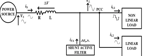
herecent growth in the use of non-linear loads has resulted in the power quality problems like voltage sag, voltage swell, voltage notch, voltage flicker, current and voltage harmonics, unbalance, excessive neutral current and interference in communication network. These disturbances range from sub cycle duration to long term steady state problems. Voltage and current harmonics causes reduction in the efficiency of the generation, transmission and utilization of electric energy. It causes a sharp increase in the zero sequence current, and therefore, increases the current in the neutral conductor. Harmonic voltages can interfere the controllers used in electronic systems and its effects are classified into two types: instantaneous effects and long term effects. The instantaneous effects are maloperation and performance degradation of electronic equipments. The long term effects are of thermal nature and are related to additional losses. Figure 1 presents a power system with sinusoidal source voltage (Vs) operating with linear and non-linear load. The non-linear load current (iL1) contains harmonic. The harmonics in the line current (is) produces non-linear voltage drop (∆V) in line impedance, which distorts the load voltage (VL). As the load voltage is distorted, the linear load current (iL2) will also be a non-sinusoidal. The solid
stateconverters draw harmonic and reactive power components of current from AC mains which affect power quality [1].
POWER SOURCE
NON LINEAR
LOAD
LINEAR LOAD R L
R L
iL2
iL1
∆V
∆V iS
VS VL
[image:1.612.315.566.254.351.2]PCC
Figure 1: Power System with Linear and Non-linear load
The total harmonic distortion (THD) is the ratio of the RMS value of the sum of all harmonic components and the RMS value of the fundamental component, for both current and voltage.
(1)
where, h is the order of harmonic.
To overcome these problems SAPF is used which satisfies the need of the dynamic and adjustable solution requirement to the power quality problems. In order to compensate the distorted currents, SAPF injects currents equal but opposite with the harmonic components, thus only the fundamental components flows in the point of common coupling (PCC).
POWER
SOURCE NON
LINEAR LOAD
LINEAR LOAD
R L
iL2
iL1
∆V iS
VS
VL
SHUNT ACTIVE FILTER iFA
PCC
Figure 2: Power System with load and shunt active filter
[image:1.612.315.566.595.694.2]The SAPF connected in parallel to the disturbing loads, unbalanced and non linear, as seen in Figure 2, causes the supply currents to be near sinusoidal and balanced. SAPF can compensate current harmonics and perform power factor correction furthermore; it allows load balancing by eliminating the current in the neutral wire [1]-[2].
This paper presents a comprehensive analysis of SAPF using two (p-q and d-q theory) algorithms for derivation of compensating signals. These compensating signals are then compared in a hysteresis controller for generation of switching signals. In section II, the control strategy of active filters is presented. In section III and IV, basic of p-q theory and its control algorithm are presented. The d-q theory and its control algorithm is presented in section V. A comparative analysis of simulation results is presented in section VI. Finally, section VII concludes the results.
II. PROCEDURAL STEPSTO CONTROL ACTIVE FILTERS The control strategy of active filters is a complex process which supposes observing certain prerequisites. It may be looked upon as a three separate steps: signal monitoring, getting compensating signals and generating gating signals.
1. Signal monitoring
For the purpose of implementation of the control algorithm, instantaneous voltage and current signals are required which are also useful to monitor total harmonic distortion (THD), power factor, active and reactive power. These signals, sensed by using potential transformer (PT) and current transformer (CT) respectively are then compared with compensating signals to generate gating signals.
2. Derivation of compensating signals
The important part of SAPF control is the development of compensating signals in terms of voltages or currents. The control methods used to generate compensating commands are based on frequency or time domain techniques. The compensation in frequency domain is based on Fourier analysis of distorted voltage or current signals to extract compensating commands but it results in large response time. The compensation in time domain are based on instantaneous derivation of compensating commands in terms of voltage or current signals from distorted voltage or current signals. This uses simple algebraic calculations and transformations. There are many control methods in time domain, few of them are:
- Instantaneous power (p-q) theory - Synchronous reference (d-q) method - Frize-Buchholz-Depenbrock (FBD) method.
3. Generation of gating signals
The gating signals to control solid state devices of SAPF are generated by using pulse width modulation (PWM), hysteresis, sliding mode or Fuzzy logic based control techniques.
A. The P-Q Theory
The p-q theory proposed in 1983 by Akagi et al [7] to control active filter (AF) is based on the time domain. It is valid for both
steady-state and transient operation as well as for generic voltage and current waveforms, allowing the control of the active filters in real-time. Since only algebraic calculations are required the additional advantage of simplicity is achieved by using this method. It consists of an algebraic transformation (Clarke transformation) of three phase voltages and currents in the a-b-c coordinate to α-β-0 coordinate. The main advantage of using Clarke transformation is separation of zero sequence components [2]-[6]. The calculation of the instantaneous power p-q theory components is given by
=
(2)
=
(3)
The instantaneous zero sequence power is given by
p
o= v
0* i
0(4)
The instantaneous real power is given by
p = v
αi
α+ v
βi
β(5)
and, the instantaneous imaginary power is given by
q = v
αi
β- v
βi
α(6)
so, the power components p and q are given by
=
(7)
These quantities are illustrated in Figure 3 for an electrical system represented in a-b-c coordinates and have the following meanings:
POWER SOURCE
LOAD
a
b
N
c
q
p
0 [image:2.612.312.542.186.321.2]p
where,
= mean value of instantaneous zero sequence power = alternated value of instantaneous zero sequence power = mean value of instantaneous real power
= alternated value of instantaneous real power q = instantaneous imaginary power.
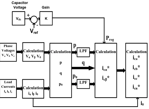
[image:3.612.314.566.71.299.2]From all the power components of p-q theory, only and are desirable. The other quantities can be compensated using a SAPF. From Figure 4 the can be compensated without the need of any power supply in the SAPF. This quantity is delivered from power supply to the load through active filter in balanced way [1]-[8]. The reactive and harmonic compensation is carried by injecting appropriate currents into the line through compensator i.e. SAPF. The dc link capacitor is required to compensate and . The instantaneous imaginary power (q) is compensated without any contribution of capacitor; this means that, the size of the capacitor does not depend on the amount of reactive power to be compensated. The can be compensated without any power supply in active filter. This quantity is delivered from the source to the load through SAPF as shown in Figure 4.
To calculate the reference compensation currents, in α-β-0 coordinates (7) is inverted; given by
= (8)
Since, the zero-sequence current must be compensated, the reference compensation current in the „0‟ coordinate is:
ic0* = i0 (9)
POWER
SOURCE LOAD
a
b
N
c
p
0p
p
p
0SHUNT ACTIVE FILTER
a
b
c
N
p
0p
0q
C
[image:3.612.313.570.403.669.2]+
_
Figure 4: Compensation of power components
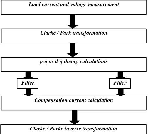
Load current and voltage measurement
Clarke / Park transformation
p-q or d-q theory calculations
Filter
Compensation current calculation
Clarke / Parke inverse transformation Filter
Figure 5: Control algorithm for extraction of compensation currents
To obtain the reference compensation currents in a-b-c coordinates the inverse transformation of (3) is applied which is given by
= (10)
POWER
SOURCE LOAD
a
b
N
c
CONTROLLER INVERTER
C
+
-Vdc
Reference Currents
Phase Voltages
Load Currents
Shunt Active Filter
i
ai
bi
ci
N(Va Vb Vc)
(ia ib ic)
Figure 6: Shunt active filter block diagram
[image:3.612.36.298.457.695.2]voltage, the controller calculates the reference currents given by (10) based on control algorithm shown in Figure 7. The inverter uses these reference currents to produce the compensation currents which are injected in power system by the inverter.
Vdc K
+
-Gain Capacitor
Voltage
Vref
Phase Voltages Va Vb Vc
Calculation Vα Vβ V0
Calculation
p
q
p0
LPF
LPF
Calculation ica*
icb*
icc*
icn*
Load Currents
ia ib ic
Calculation iα iβ i0
Calculation
icα*
icβ*
Preg
q p
p0
[image:4.612.40.300.104.294.2]i0
Figure 7: Calculation of p-q theory components
B. Synchronous Reference Frame Theory
The synchronous reference frame theory or d-q theory [8] is based on time domain reference signal estimation techniques. It performs the operation in steady state or transient state as well as for generic voltage and current waveforms. It allows controlling the active power filters in real time system. Another important characteristic of this theory is the simplicity of the calculations, which involves only algebraic calculation. In this strategy, the reference frame d-q-0 is determined by the transformation angle θ with respect to the α-β-0 frame applied in the p-q theory [6]. It is based on the transformation of the stationary reference frame three phase variables (a,b,c) to synchronous reference frame variables (d,q,0) whose direct (d) and quadrature (q) axes rotate in space at the synchronous speed , which is the angular electrical speed of the rotating magnetic field of the three phase supply given by , where is the frequency of the supply. If θ is the transformation angle, then the current transformation from a-b-c to d-q-0 frame is calculated as
=
(11)
where, (12)
The sine and cosine functions help to maintain the synchronization with supply voltage and current. The d-q transformation output signals are dependent on the load current
(fundamental and harmonic components) and the performance of the Phase Locked Loop (PLL). The PLL circuit provides the rotation speed (rad/sec) of the rotating reference frame, where W is set as fundamental frequency component and 30 degree phase angle followed by sin and cos for synchronization. The (id - iq) currents are sent through low pass filter (LPF) for filtering the harmonic components of the load current, which allows only the fundamental frequency components [3]. The LPF is second order butterworth filter used for eliminating the higher order harmonics. The PI controller is used to eliminate the steady-state error of the DC component of the d-axis reference signals. The DC side capacitor voltage of inverter is sensed and compared with desired reference voltage for calculating the error voltage. This error voltage is passed through a PI controller whose propagation gain (KP) and integral gain (KI) is taken as 0.1 and 1 respectively.
iabc abc to
dq
LPF
dq to abc
P-I Controller Vdc
Gain K PLL
+
-+
[image:4.612.323.585.267.405.2]-i
abc*
Figure 8: Synchronous reference theory based control algorithm
III. SIMULATION RESULTS
The purpose of the simulation is to show the effectiveness of p-q and d-q methods for maintaining sinusoidal source currents when the source supplying a non-linear load. The MATLAB/Simulink simulation tool is used to develop a model that allowed the simulation of the p-q and d-q theory calculations, which are implemented in the controller of the SAPF (Figure 7 and 8). The load is simulated to include harmonic distortion from a three phase uncontrolled rectifier.
(b) Load currents without SAPF
(c) Three phase compensating currents
(d) Three phase load currents with SAPF
Figure 9: Simulation results for ideal voltage source and thyristor rectifier load
[image:5.612.40.523.59.580.2]Because of non-linear load the source current contains harmonic components as shown in Figure 9 (b). To make the source current distortion free, SAPF operate to compensate the current harmonics by injecting the current of variable magnitude and phase as shown in Figure 9 (c). The Figure 9 (d) indicates that after compensation the main currents are sinusoidal even when the load is non linear.
TABLE I: Harmonic compensation by p-q theory method
Load
Currents THD without compensation
THD with compensation
Ia 20.25% 1.21%
Ib 21.07% 1.22%
Ic 21.69% 1.28%
TABLE II: Harmonic compensation by d-q theory method
Load
Currents THD without compensation
THD with compensation
Ia 20.25% 1.31%
Ib 21.07% 1.34%
Ic 21.69% 1.37%
From Table I and II, it is seen that without compensation, the THD level of the source current was in between 20-22% which do not comply with the IEEE 519 harmonic standards [9]. After compensation by p-q and d-q theory, the THD level of the source current is reduced considerably for all three phases which comply with the IEEE 519 standards. Comparing these tables it is confirmed that p-q theory gives better performance than the d-q theory method.
IV. CONCLUSION
In this paper the performance analysis of p-q and d-q methods of compensation current generation for SAPF under distorted supply and non-linear load conditions based on simulation studies is discussed. Comparative study brings that, the p-q theory gives a better approach than synchronous reference frame (d-q) theory for compensation ofharmonic currents and takes appropriate corrective measure for the THD in improvement of the power under distorted supply and non-linear load conditions.
REFERENCES
[1] Bhim Singh, Kamal Al-Haddad and Ambrish Chandra, "Review of active filters for power quality improvement," SpringerIEEE Transaction on Industrial Electronics, Vol.-46 No. 5, Oct. 1999.
[2] Joao L. Afonso, M. J. Sepulveda Freitas, and Julio S. Martins, “ p-q theory power components calculations,” ISIE 2003, IEEE International Symposium on Industrial Electronics Rio de Janeiro, Brasil 9-11 Junho de 2003, ISBN: 0-7803-7912-8
[3] Murat Kale and Engin Ozdemirc, “Harmonic and reactive power compensation with shunt active power filter under non-ideal mains voltage,”Electrical power systems research 74(2005) 363-370.
[4] Jora M. Gonda, Anantha adithya and Sumam david S., “Performance analysis of compensation current extraction circuit for three phase three wire shunt active power filter under unbalance supply,” IEEE 978-4244-4331-4/09-2009.
[6] Joao L. Afonso, H.J. Ribeiro da silva and Julio S. Martins, “Active Filters for power quality improvement,” IEEE porto power Tech 10-13 set 2001 ISBN:0 7803 7139 9.
[7] H. Akagi, Y. Kanazawa and A. Nabae, “Generalized theory of the instantaneous reactive power in three-phase circuits,” IPEC'83 -Int. Power Electronics Conf., Tokyo, Japan, 1983, pp. 1375-1386.
[8] V. Soares, P. Verdelho and G. Marques, “Active power filter control circuit based on the instantaneous active and reactive current id-iq method,” Proc. of PESC'97, Vol. 2, 1997 pp. 1096 –1101.
[9] “IEEE recommended practices and requirements for harmonic control in electrical power systems,” IEEE Std519-1992
AUTHORS
First Author – S.S. Wamane, M.Tech, VJTI - Mumbai [email protected]
Second Author – J.R. Baviskar, PhD, VJTI - Mumbai [email protected]
Third Author – S.R. Wagh, PhD, VJTI - Mumbai [email protected]