CORPORATION ROBOTS
SALEH FARAJ MANSOUR
A thesis submitted in fulfillment of the requirement for the award of the Degree of Master of Electrical Engineering
Faculty of Electrical and Electronic Engineering University Tun Hussein Onn Malaysia
V
ABSTRACT
VI
ABSTRAK
VII
CONTENTS
TITLE I
DECLARATION II
DEDICATION III
ACKNOWLEDGEMENT IV
ABSTRACT V
ABSTRAK VI
CONTENTS VII
LIST OF TABLES X
LIST OF FIGURES XI
LIST OF SYMBOLS XIII
LIST OF APPENDIX XIV
CHAPTER 1 INTRODUCTION 1
1.1 Introduction 1
1.2 Problem Statement 3
1.3 Objectives 4
1.4 Scope of project 4
VIII
CHAPTER 2 LITERATURE REVIEW 6
2.1 Introduction 6
2.2 Development of Road Vehicle Convoy System 6 2.3 Low Cost Sensing for Autonomous Car Driving on
Road
7
2.4 Leader/Follower Behaviour using Ultrasonic transmitter and receiver
9
2.5 Scale Invariant Feature Transform (SIFT) algorithm
10
2.6 The X80 Robot 12
2.7 Raccoon 13
CHAPTER 3 METHADOLOGY 15
3.1 Introduction 15
3.2 Project procedures 15
3.3 Design process 17
3.4 Design Prototype 18
3.4.1 Control system 18
3.4.2 The Sensor 19
3.4.3 The comparator and sensor circuit 21
3.4.4 The Processor Unit 22
3.4.5 Motor driver 25
3.4.6 DC motor: 27
3.4.7 Wheels 28
3.4.8 LM7805 Voltage Regulator 29
3.4.9 Programming 30
CHAPTER 4
RESULT AND DISCUSSION
344.1 Introduction 34
4.2 Testing the Motor Circuit 34
IX
4.4 Output Waveform 37
4.5 Mode of movement 38
4.6 Final result for line following robots carrying load 40
CHAPTER 5 CONCLUSION AND RECOMMENDATION 42
5.1 Conclusion 42
5.2 Recommendation 43
REFFERENCE 44
X
LIST OF TABLES
3.1 sensor arrays Declaration of ports
19
3.2 31
XI
LIST OF FIGURES
1.1 Block diagram of mobile robot 3
2.1 HANS Vehicle 7
2.2 Occupancy Grid 9
2.3 Maxelbot 10
2.4 Robot Follower Using SIFT Algorithm 11
2.5 X80 ROBOT 12
2.6 IR sensor on X80 robot 12
3.1 Overall of the project 16
3.2 Flowchart of design process 17
3.3 block diagram of line following system 18
3.4 The basic design of IR sensor 20
3.5 infrared reflection 21
3.6 schematic of comparator and IR sensor circuit 22
3.7 Microprocessor Unit 24
3.8 PIC16F877A 25
3.9 driver motor MD30B 26
3.10 Flux magnet 27
3.11 DC motor 28
3.12 The motor and caster placed on robot 29
XII
3.14 Flow chat of control program 32
3.15 Flow chart of line following robots 33
4.1 Waveform of output voltage at the motor driver when moving forward
38
4.2 Flow Chart of programming Development for line following robot
39
XIII
LIST OF SYMBOLS
V - Voltage
+ - Positive
- - Negative
I - Input
O - Output
ICP - In-circuit debugger
CCP - Capture - compare
PWM - Pulse – width modulation
PSP - Parallel slave port
RPM - Rotation per minute
XIV
LIST OF APPENDIXS
A Coding code of line following robots 46
CHAPTER 1
1.1 Introduction
2
3
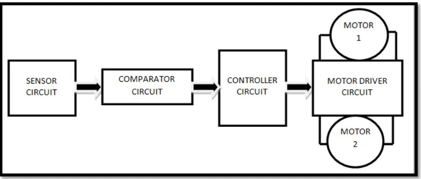
Figure 1.1: Block diagram of mobile robot
A mobile robot is divided into two main parts, namely the software and hardware. For the software, PIC16F877A micro controller will be use for system controller for this robot. While on the hardware side, a circuit will be built and connected to sensors and motors. For this project a better of reflective sensor is to use Infrared Light (IR) and NPN transistor, as less much interferences. The control has 6 modes of operation, turn left/right, forward/reverse, and stop. The actual action is caused by controlling the direction/speed of the two motors (the two back wheels), thus causing. Two motors as an output will control by motor driver that connected to the PIC16F877A
1.2 Problem statement
4
1.3Objectives
In this master project the objectives divided into:
1- To design single line following robot as leader. 2- To design second line following robot as slave robot.
3- To develop a programming code suitable for both robots to follow the line.
1.4 Scope of project
Scope of this project proposal is:
1- Develop two following line robots. In which the first robot as leader and the second robot as slave.
2- The robots controller developed by using PIC16F877A microcontroller that is program with assembly language.
3- Use DC motors as actuators with suitable motor driver.
1.5 Organization of project
Chapter one: Discuses the introduction (problem statement, Objectives, Scope of project and Organization of project)
5
Chapter three: Discuses the methodology
CHAPTER 2
LITERATURE REVIEW
2.1 Introduction
This chapter reviews some of previous work on development of single and corporation robots.
2.2 Development of road vehicle convoy system
7
Both vehicles in this project utilize PIC 18F454 microcontroller (MCU) as the “brain” for both vehicles. The following vehicle utilizes ultrasonic sensor (R40-16 & T40-16) to detect and measure the distance between the leading and the following vehicle. When the ultrasonic sensor sends a wave with certain frequency and received it back through reflection after hit the obstacle, the information was sent to the PIC microcontroller. The Microcontroller then perform calculation to obtain the distance between the vehicles and follow the vehicle. The C programming language was used for the programming part in this project. The MPLAB IDE version 7.43 with C18 compiler support C language programming.
The robot follower in [2] has a numbers of limitations. Firstly, the following vehicle cannot follow the leading vehicle when the leading vehicle turn left or right from the straight line. Besides, the following vehicle could not avoid any obstacle or collision. The following vehicle also could not vary its speed in accordance to the distance between the vehicles. It can travel at a constant speed only.
[image:18.612.116.536.457.688.2]2.3 Low Cost Sensing for Autonomous Car Driving on Road
8
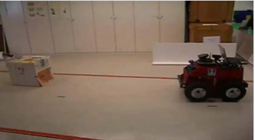
According to [3], a car-like robot equipped with a system called HANS, is able to navigate in an autonomous and safe manner, performing trajectories similar to the ones carried out by human drivers. The system was successfully tested in both simulations and in a laboratory environment using a mobile robot to emulate the carlike vehicle. As a result, this autonomous car can follow the front vehicle in curve road. Besides, this mobile robot also can follow the road, keeping the car in the right lane, maintaining safe distances between vehicles, and avoiding collision. For this mobile robot, it is assumed that there are no cars driving faster than the HANS vehicle which means that no cars will appear from behind.
HANS in [3] uses a low resolution web camera located in the centre of the vehicle behind the rear-view mirror and a set of sixteen sonar sensor. The key role of the camera is to act as a vision system. It is used to detect the side lines that bound the traffic lanes, the position and orientation of the robot relative to these lines, and the vehicles driving ahead and determining their lane and distance to the robot.
9
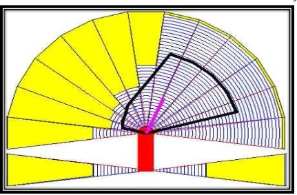
Figure 2.2: Occupancy Grid
2.4 Leader/Follower Behavior using ultrasonic transmitter and receiver
10
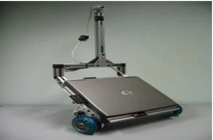
Figure 2.3 : Maxelbot
Limitation of this project is that the effective distance that can be measured by the follower from the leader is about one meter only. Once the distance of the leader is more than 1 meter from the follower, the follower cannot follow the leader.
The advantage of this method is that the cost of the hardware is relatively low when compared to the vision system base method. Beside, the robot is more robust when performing the following task in multiple obstacles environment compared to following system utilizing IR sensors only.
2.5 Scale Invariant Feature Transform (SIFT) algorithm
11
[image:22.612.116.538.152.429.2]target is recognized, it estimates the position of the target. Then it uses the PID controller to control the motor to maintain the minimum distance between the follower and the target.
Figure 2.4: Robot Follower Using SIFT Algorithm
There are a number of limitations of this method for following behavior. The 3.5 meter effective distance for the recognition system is adequate for a small robots operating indoors, but would not be adequate for larger outdoor platforms. Additionally, direct pursuit of the leader’s current position is quite impropriate and does not work well in complex environments. PID control loops were time consuming to properly tune, and the performance of the simple robot platform limits the applicability of the system as implemented to wider applications.
12
trained objects, opening the way for new avenues of human robot cooperation. And despite the image recognition software iterating at only 2Hz, the controllers were able to perform adequately for the task. With the application of increased processing power to the problem, robot control performance would improve.
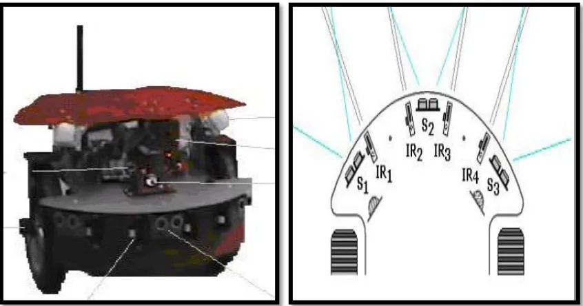
2.6 The X80 Robot
[image:23.612.114.537.381.603.2]Figure 2.5 shows the image of the X80 robot. According to [6], the X80 robot has 4 Infrared sensors and 3 sonar sensors to perform the following task. It is used to pursuit the direct position of leader robot. The position of each sensor is arranged as shown in figure 2.6. The following task is heavily depending on the IR sensors only. The other 3 sonar sensors are used only to perform the checking on the measurement of distance return by the IR sensors.
13
The limitation of the robot is that this robot can only perform the following task in free space. The follower will lost the target if it is operating in the space full of the obstacles. Besides, it may also easily lost track of the leader robot. Another limitation is that the follower robot needs to stop during turning direction when the leader robot turns direction.
Despite its limitation, the X80 robot can follow the leader robot at low speed in free space.
2.7 Raccoon
RACCOON is a vision-based system that tracks car taillights at night as described in [7]. The RACCOON system was developed at Carnegie Mellon University. The prototype was built and integrated with RACCOON system. This system enables the autonomous vehicle to chase the leading car effectively under low light condition.
According to [7], this project was inspired by following reason: a) The road cannot be seen clearly at night.
b) Unlit landmarks cannot be detected so corners and intersections have to be negotiated based solely on the observed actions of the lead vehicle at night.
Problems above make the following vehicle cannot detect the leading vehicle clearly at night using normal vision system and algorithm. In normal algorithm, the taillights can be easily extracted from a dark background. After the extraction, the autonomous car steers toward the taillight of lead vehicle. The autonomous vehicle may follow the lead vehicle successfully with this algorithm.
14
CHAPTER 3
METHADOLOGY
3.1 Introduction
This chapter explains the methods used to implement this project. The first one is to identify and understand the flow of operation system. The project development consists of two stages. The first stage is assembling the project. Meanwhile at the second stage is troubleshooting and taken the data of each part of the project.
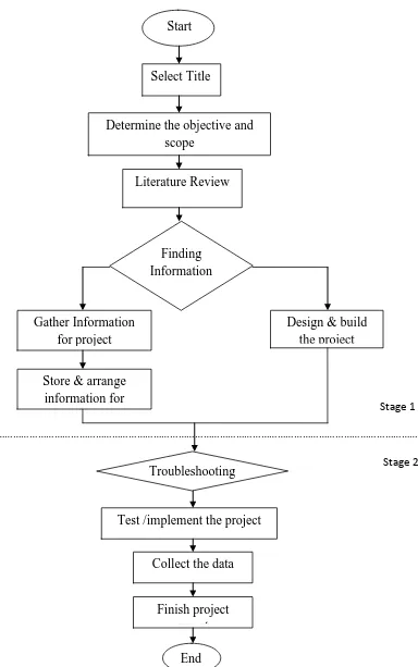
3.2 Project procedures
16
Stage 1
……….
[image:27.612.131.515.62.675.2]Stage 2
Figure 3.1: Overall of the project
Start
Select Title
Determine the objective and scope Literature Review Finding Information Gather Information for project
Store & arrange information for project report
Design & build the project
Troubleshooting
Test /implement the project
Collect the data
17
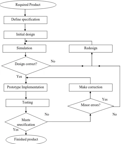
3.3 Design process
To develop a project, it will start by introducing a typical development cycle in the most general terms. Then it will focuses on the particular aspects that pertain to the design of logic circuit. The flowchart in figure 3.2 depicts a typical design process.
No
Yes
Yes
No No
[image:28.612.88.503.186.677.2]Yes
18
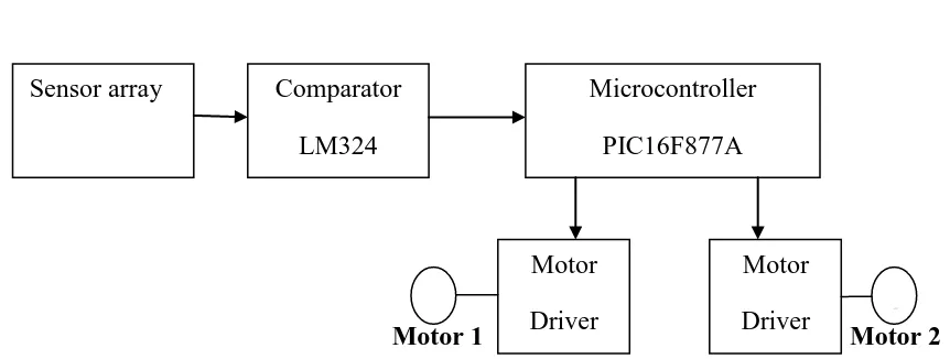
3.4 Design Prototype
This project consists several blocks such as: 1) Sensor
2) Comparator 3) Processor Unit 4) Motor Driver
[image:29.612.114.545.236.399.2]Motor 1 Motor 2
Figure 3.3: block diagram of line following system
3.4.1 Control system
The electrical circuit of the project are compared the analog signal received from sensors and then transmit the result to the processor in digit ,, or ,1, and some of them send the 0 analog signals to the processor ought to convert them to digital form.
Sensor array Comparator LM324
Microcontroller PIC16F877A
Motor Driver Motor
19
3.4.2 The sensor
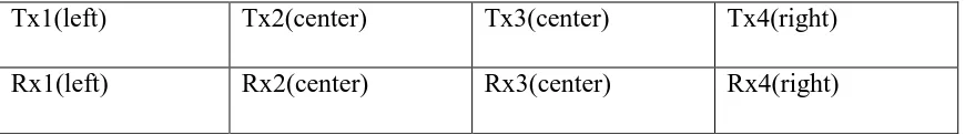
In this project, mobile robot uses 4 IR LEDs (Tx) and 4 IR sensors (Rx) with distance between the two sensors is 15mm. the first Rx receives an analog signal that depends on the intensity of light reflected by the black line of emitted beam by the Tx. These signals are sent to the comparator LM324 with creates digital signals(0 or 1) that are sent to microcontroller PIC.
Hence, the distance between sensors and ground surface is important and it is more important than how to put sensors near each other. The distance between sensors and ground surface must be 2 to 10mm and the distance between each sensor is depend on the line width.
[image:30.612.114.549.360.421.2]Mobil robot used four pair of sensors as shown in Table 1.
Table 3.1: sensor arrays
Tx1(left) Tx2(center) Tx3(center) Tx4(right)
Rx1(left) Rx2(center) Rx3(center) Rx4(right)
20
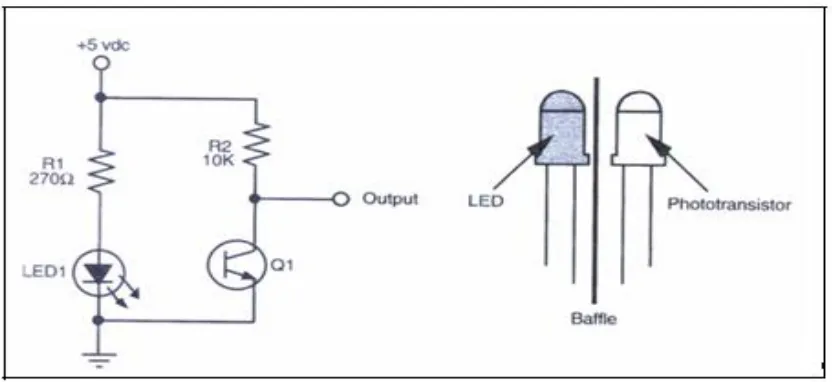
Figure 3.4 : The basic design of IR sensor
These devices work by measuring the amount of light that is reflected into the receiver. Because the receiver also responds to ambient light, the device works best when well shielded from ambient light, and when the distance between the sensor and the reflective surface is small(less than 5 mm). IR reflectance sensors are often used to detect white and black surface. White surface generally reflect well, white black surface reflect poorly.
IR LED emits infrared radiation. This radiation illuminates the surface in front of LED. Surface reflects the infrared light Depending on reflectivity of the surface, amount of light reflected varies. This reflected light is made incident on reverse biased IR
21
Figure 3.5: infrared reflection
3.4.3 The comparator and sensor circuit
A comparator circuit compares two voltage signals and determines which one is greater. The result of this comparison is indicated by the output voltage. If the op-amp’s output is saturated in the positive direction, the no inverting input (+) is a greater, or more positive, voltage than the inverting input (-), all voltages measured with respect to ground. If the op-amp’s voltage is near the negative supply voltage (in this case, 0 volts, or ground potential), it means the inverting input (-) has a greater voltage applied to it than the no inverting input (+).
22
Figure 3.6: schematic of comparator and IR sensor circuit
3.4.4 The Processor Unit
A microcontroller is single chip used to control other devices. It was developed out of the need for small, low power systems. One could describe a microcontroller as a mini computer. This is because microcontrollers typical do not have the expandability or performance that microprocessors have. The primary role of these microcontrollers is to provide inexpensive, programmable logic control and interfacing to external device. Thus, they typically are not required to provide highly complex function. But they are capable of providing sophisticated control of different application.
23
The microcontroller can provide, in a simplified form, all the main elements of the conventional microprocessor system on one chip. As result, less complex applications can be designed and built quickly and cheaply. A working system can consist of microcontroller chip and just a few external components for feeding data in and out, and generating the clock.
In this project, PIC16F877A was used as processor, PIC16f877A is a good flash microcontroller that has many features a 40-pin and 5 input-output (I/O) ports. This flash microcontroller may be programmed and erased instantly, without the need for a UV light sours, to speed program testing. Reprogram ability offer a highly flexible solution today’s ever- changing market demands, where product updates and modification are routinely carried out in the field. Port A consists of 6 pins which can be set up as either digital I/O or analog inputs. Port B is an 8 pin port which can be used for both digital I/O operations and in-circuit debugger (ICD) operations. Port C, on the other hand, is a 5-pin multi-functional port, which can be used for digital I/O, as capture-compare (CCP) input, or pulse-width modulation (PWM) output.
24
Figure 3.7: Microprocessor Unit
The PIC16F877A microcontrollers carry a large memory array, which can be divided into three types:
44
REFFERENCE
1- Colony of robots: New Challenge Workshop invited key lecture Gastón Lefranc.2008
2- Gan Hui Wen. “Development of a road vehicle model for road vehicle convoy
System”, UTM 2007
3- Jo˜ao Sequeira, Andr´e Gonc¸alves, and Andr´e Godinho. Low cost Sensing For
Autonomous Car Driving In Highways. 2007.
4- Rozan Boudville. Obstacle detection and avoidance mobile robot. Universiti Teknologi Malaysia. 2004.
5- J. Giesbrecht and DRDC Suffield. Leader/Follower Behaviour Using the SIFT
45
6- Adrian Korodi, Alexandru Codrean, Liviu Banita,Constantin Olosencu. Aspects
Regarding the Object Following Control Procedure for Wheeled Mobile Robots 2008.
7- Rahul Sukthankar. RACCOON: A Real-time Autonomous Car Chaser Operating
Optimally at Night. 2008
8- Omkar . “How to make simple infrared sensor modules “. February 19,2008 , From ”http://elecrom.wordpress.com/2008/02/19/how-to-make-simple-