International Journal of Emerging Technology and Advanced Engineering
Website: www.ijetae.com (ISSN 2250-2459, ISO 9001:2008 Certified Journal, Volume 6, Issue 8, August 2016)
1
Performance Testing of Engine under Alcohol Blending with
Data Acquisition System
Bagul A. D.
1, Rane H. S.
2, Chaudhari S. A.
3, Waghodekar S.V.
41,2,3,4Asst. Professor in Mechanical Engineering Dept., N.M.K.C. College of Engineering and Technology, Jalgaon,
Maharashtra, India
Abstract - This study investigates the effects of ethanol-blended gasoline with oxygenated additives on a multi – cylinder Spark Ignition (SI) Engine and their comparison with those of pure gasoline. These fuels are easily available in all cities of India at economical cost. These fuels give different combustion rate, power output as they have different chemical composition & properties.
The experiments were conducted in two stages. In stage I, the test is carried out using 99.9% pure gasoline fuel. In stage II, 5%, 10%, 15% ethanol and rest of gasoline (in %) blends are used to carry out the tests on the test rig. Performance tests were conducted on a multi – cylinder SI Engine coupled with an eddy current dynamometer. The experimental results proved that the blend increased brake thermal efficiency more than a sole fuel, such as gasoline. The results of the study show that 10% ethanol blends can be used in internal combustion engines without any negative drawbacks. For 15% blend some modifications in the engine parts are required. A mathematical model using DAS software was developed to predict the SI engine performance for different blend ratios. The mechanical and heat losses in the engine which is not included in this study.
Keywords-- SI engine, Ethanol blends, Brake thermal efficiency, DAS system.
I. INTRODUCTION
A)Ethanol as an alternative fuel for SI engine
Ethanol (C2H5OH) is a renewable fuel. It can be
produced from agricultural feed stocks, such as sugarcane and also from forestry wood wastes and agricultural residues. It can also be derived chemically from ethylene or ethane. Ethanol has a simple molecular structure with well-defined physical and chemical properties. Ethanol can be employed as a transportation fuel even in its original form and can also be easily blended with other fuels, such as gasoline and diesel. Currently, there is a lot of interest in ethanol production from renewable feed stocks, to minimize the emissions of carbon dioxide, which is a greenhouse gas that contributes to global warming. The addition of ethanol to gasoline results in the enhancement of the octane number in blended fuels and changes the distillation temperature, as well as reducing CO2 emissions.
[1]
Alcohols, such as ethanol, are colourless liquids with mild characteristic odours that can be produced by fermentation of biomass crops, such as sugarcane, wheat and wood. Using alcohols as fuel for Spark Ignition (SI) engine have some advantages over gasoline. Ethanol has better anti-knock characteristics and the engine’s thermal efficiency improves with the increase in compression ratio. [2] Alcohol burns with lower flame temperature and luminosity owing to the decrease of the peak temperature inside emissions are the cylinder so that the heat loss and NOx lowered. Ethanol has high latent heat of vaporization. The latent heat cools the intake air and hence increases the density and volumetric efficiency. However, the oxygen content in ethanol reduces the heating value more than gasoline does. It is evident that ethanol can be used as a fuel in SI engines. [3] Hsieh et al. experimentally investigated the engine performance and the emission of an SI engine using an ethanol–gasoline blend fuel in the ratios of 5%, 10%, 20% and 30%. The results showed that when the ethanol rate increased, the heating value of the blended fuel was found to have decreased but at the same time, it increased the engine torque. Ethanol has high affinity for water as it contains a certain amount of water in it. This is not a problem for pure ethanol because it fully mixes with water, but some serious problems may arise when gasoline-ethanol blends are used. Phase separation can occur in these blends since gasoline and ethanol are immiscible.
Countries like Germany, Brazil are using E10 fuel for public transportation. After practical observations it is found that this E10 is helpful in both environment friendly points of view. Already 5% ethanol blending fuel is in use commercially in Maharashtra state and the state government is on the verge of launching 10% ethanol blending fuel for transportation in upcoming years. [3]
This paper deals with parameters testing for stroke 4-cylinder computerized test rig for the various blends (5%, 10%, & 15%) of ethanol fuel and their comparison with parameters for only gasoline fuel.
International Journal of Emerging Technology and Advanced Engineering
Website: www.ijetae.com (ISSN 2250-2459, ISO 9001:2008 Certified Journal, Volume 6, Issue 8, August 2016)238
B)Fuels For SI Engine
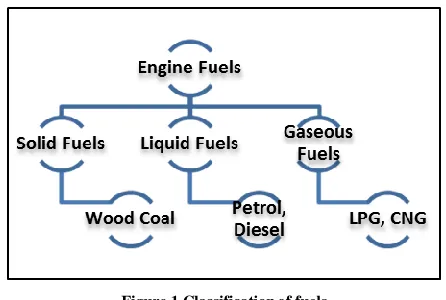
IC engines can run on different kinds of fuel, including liquid, gaseous and even solid fuels. The properties and the character of the fuel exercise profound influence on the design, power output, efficiency, fuel consumption and the reliability and durability of the engine.
The use of solid fuels present problems of complicated injection systems, as well as difficulties associated with solid residual ash, and hence are not popular. Gaseous fuels present problems of storage and handling of large volumes. Hence for mobile use its use gets restricted. But gaseous fuels do find use for stationary power plants particularly when gas is readily available at the location nearby. Thus, liquid fuels find abundant use in IC engines.[8]
[image:2.612.56.279.324.474.2]The figure 1 shows the classification of fuels used in IC engines.
Figure 1 Classificationof fuels
Gasoline which is mostly used in present day SI engines. Gasolineis usually a blend of several low boiling paraffins, napthanes and aromatics in varying proportions. Some of the important qualities of gasoline are stated below;
i)Volatility,
ii) Starting and warm-up, iii)Operating range performance, iv)Crank case dilution,
v) Antiknock quality, vi)Gum deposites, etc.
Ethanol and Gasoline Mixture Properties
Ethanol has been used as a gasoline fuel additive since the late 1970s when it was used as a fuel extender due to gasoline shortages after the oil embargo as well as an octane enhancer since it improved the anti-knock performance of gasoline. In this decade, when many state governments prohibited the use of predominant oxygenate, MTBE ethanol then become oxygenate of choice.
Several states also have required ethanol use in winter (“gasohol”) as a way to reduce carbon monoxide emissions.
Some (but not all) of the changes in fuel properties due to the addition of ethanol to gasoline include:
Change in Octane Number- In general, addition of ethanol up to a certain amount improves gasoline’s octane number due to its excellent anti-knock properties. Engines specifically designed to use high octane fuels, such as high performance engines, may use higher compression ratios or increase charge air compression to increase power output. Change in Fuel Volatility- A fuel's ability to vaporize is referred to as its volatility. It is represented by several measurements, including vapor pressure, vapor-liquid ratio and the amount vaporized at different temperatures (distillation). If the vapor pressure of the fuel is too low, that may cause problems in starting engines in cold temperatures; if it is too high, it may cause vapor lock at high temperatures.
Gasoline does not ignite as a liquid, only as a vapor. There must be sufficient fuel vapor present inside the combustion chamber to get the engine to start. This vaporization is governed by the fuel’s overall volatility, measured by its distillation curve. Within a certain temperature range (that varies with each blend), ethanol decreases the temperature at which the fuel vaporizes, which, theoretically, should help combustion. However, ethanol blends also require more heat to vaporize than gasoline, which means that less vapor than predicted by the distillation curve, is actually present inside the cylinder. Thus not only the distillation percentage versus temperature, but the heat input required to achieve the temperature are important to understand how fuel differences will interact with the engine design and the operating conditions. Other concerns about low temperature fuel characteristics of blends include
a) Increased viscosity of ethanol/gasoline blends which may impede fuel flow.
b) Phase separation in the vehicle fuel system due to reduced water solubility.
International Journal of Emerging Technology and Advanced Engineering
Website: www.ijetae.com (ISSN 2250-2459, ISO 9001:2008 Certified Journal, Volume 6, Issue 8, August 2016)239
Even in the closed loop engine systems used in some off-road engines and in most late-model vehicles, there remains the likelihood of vapor lock.
Effect on Water Solubility and Phase Separation- of a single phase gasoline into a "gasoline phase" and a "water phase" can occur when too much water is introduced into the fuel tank. Water contamination is most commonly caused by improper fuel storage practices at the fuel distribution or retail level, or the accidental introduction of water during vehicle refueling. Water has a higher density than gasoline, so if water separates, it will form a layer below the gasoline. Because most engines obtain their fuel from, or near, the bottom of the fuel tank, engines will not run if the fuel pick up is in the water phase layer. Typically, gasoline can absorb only very small amounts of water before phase separation occurs. Ethanol/gasoline blends, due to ethanol's greater affinity with water, can absorb significantly more water without phase separation occurring than gasoline. Ethanol blends can actually dry out tanks by absorbing the water and allowing it to be drawn harmlessly into the engine with the gasoline. If, however, too much water is introduced into an ethanol blend, the water and most of the ethanol will separate from the gasoline and the remaining ethanol. The amount of water that can be absorbed by ethanol/gasoline blends, without phase separation, varies from 0.3 to 0.5 volume percent, depending on temperature, aromatics, and ethanol content. If phase separation were to occur, the ethanol/water mixture would be drawn into the engine and the engine would most likely stop.
In some situations, ethanol/gasoline blends might absorb water vapor from the atmosphere, leading to phase separation. Such problems are of greater concern for engines with open-vented fuel tanks that are operated in humid environments, such as marine engines. Additionally, more complex phenomena such as lubricating oil/fuel separation (in 2-stroke engines) and temperature-induced phase separation of various fuel components have also been noted.
Comparison of Ethanol and Gasoline
• Auto ignition temperature of ethanol is lower than the gasoline.
• Safe for transportation and storage.
• Evaporation of ethanol is 3-5 times higher than gasoline. • Heating value of ethanol is lower than gasoline, hence it
need 1.5-1.8 times more ethanol to achieve same energy output.
• Stoichiometric air-fuel ratio (AFR) of alcohol is lower than gasoline.
• Ethanol bended fuel increases octane number.
• Higher octane number leads to better combustions and emission.
• There is formation of aldehyde in tail pipe.
• The formation of aldehyde can be reduced by adding fin in intake manifold [11]. Table 1 shows the properties of ethanol and gasoline.
Table 1
Properties of ethanol and gasoline
Property Unit Ethanol Gasoline
Chemical Formula - C2H5OH C4toC12
Molecular Weight g/mol 46 100–105
Carbon mass% 52.2% 85-88%
Hydrogen mass% 13.1% 12–15%
Oxygen mass% 37.7% 0%
LiquidDensity,20°C kg/m3 0.783
0.72-0.78 Boiling
temperature,1atm °C 78.4(20) 27(16) Flash point temperature,
atmospheric conditions °C 12 42 Heat of Combustion
(Lower Heating Value) kJ/kg 26900 42000
II. THEORY WORK
A)Working Principle of SI Engine
If an engine is to work successfully then it has follow a cycle of operations in a sequential manner. The sequence is quite rigid & cannot be changed. The working principle of SI engine described below. The credit inventing the Spark-Ignition engines goes to Nicolaus A. Otto (1876). Therefore this cycle often referred as Otto cycle.
In a four stroke engine, the cycle of operations is completed in four strokes of piston or two revolutions of the crankshaft. During the four strokes, there are five events to be completed that are, suction, compression, combustion, expansion & exhaust. Each stroke consists of 1800 of crankshaft rotation & hence four stroke cycle is completed through 7200 of crank rotation. The cycle of operation for an ideal four-stroke SI engine consist of following four strokes. [6]
1) Suction stroke. 2) Compression stroke.
International Journal of Emerging Technology and Advanced Engineering
Website: www.ijetae.com (ISSN 2250-2459, ISO 9001:2008 Certified Journal, Volume 6, Issue 8, August 2016)240
1) Suction stroke: - On the Suction or induction stroke of the piston, the piston descends from the top (TDC) of the cylinder to the bottom (BDC) of the cylinder, reducing the pressure inside the cylinder. A mixture of fuel and air is forced by atmospheric (or greater) pressure into the cylinder through the intake port. The intake valve then closes. The suction stroke is shown in figure 2 (a) & in figure 3 on p-v diagram.
[image:4.612.74.267.308.405.2]2) Compression stroke: - With both intake and exhaust valves closed, the piston returns to the top of the cylinder compressing the fuel-air mixture. This is known as the compression stroke. The energy required to move piston from BDC to TDC is taken from flywheel. This stroke can be shown on figure 2 (b) & in figure 3 on p-v diagram.
Figure 2 working principle of a four-stroke SI engine
3) Power stroke:- While the piston is close to Top Dead Center, the compressed air–fuel mixture is ignited, usually by a spark plug (for a gasoline or Otto cycle engine) or by the heat and pressure of compression (for a diesel cycle or compression ignition engine). The resulting massive pressure from the combustion of the compressed fuel-air mixture drives the piston back down toward BDC with tremendous force. This is known as the power stroke, which is the main source of the engine's torque and power. This stroke can be represented in figure 2 (c) & in figure 3 on p-v diagram.
4) Exhaust stroke: -During the exhaust stroke, the
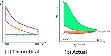
Figure 3 P-V diagram of a four-stroke SI engine
Piston once again returns to TDC while the exhaust valve is open. This action evacuates the products of combustion from the cylinder by pushing the burnt fuel-air mixture through the exhaust valve. This stroke can be represented in figure 2 (d) & in figure 3 on p-v diagram. [7]
Figure 3 (b) shows the actual indicator diagram of four stroke SI engine. It may be noted that line 5-1 is below the atmospheric pressure line. This is due to the fact that owing to restricted area of the inlet passages the entering fuel air mixture cannot cope with the speed of the piston. The exhaust line 4-5 is slightly above the atmospheric pressure line. This is due to restricted exhaust passages which do not allow the exhaust gases to leave the engine-cylinder quickly [8].
The loop which has area 4-5-1 is called negative loop it gives the pumping loss due to admission of air-mixture and removal of exhaust gases. The area 1-2-3-4 is the total or gross work obtained from the piston and net work done can be obtained by subtracting area 4-5-1 from the area 1-2-3-4 [8].
B)Phenomenon of knock in SI engine
A very sudden rise of pressure during combustion accompanied by metallic hammer like sound is called knocking.
The process phenomenon of detonation or knocking may be explained by referring to the figure 4 which shows the cross section of the combustion chamber with flame advancing from the spark plug location A. the advancing flame front compresses the end charge BB’D farthest from the spark plug, thus raising its temperature.
[image:4.612.78.269.575.671.2]International Journal of Emerging Technology and Advanced Engineering
Website: www.ijetae.com (ISSN 2250-2459, ISO 9001:2008 Certified Journal, Volume 6, Issue 8, August 2016) [image:5.612.104.222.144.244.2]241
Figure 4 Cross section of chamber with flame advanced
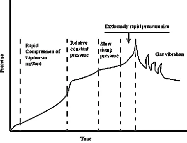
Figure 5 Pressure vs. flame propagation time
The figure 5 shows graph of variation of pressure against flame propagation time. This graph shows that as the propagation time passes the pressure rises. The rapid compression takes place after 50 microseconds of initial time. Due to molecular structure of fuel the knocking observed & gas vibration takes place in combustion chamber. This results in engine noise & vibration. There are two general theories of knocking.
1. The auto-ignition theory. 2. The detonation theory.
1) The auto ignition theory:-Auto ignition refers to initiation of combustion without the necessity of a flame. The auto ignition theory of knock assumes that the flame velocity is normal before the onset-of auto-ignition and that gas vibrations are created by number of end gas elements auto igniting almost simultaneously.
2) The detonation theory:-In the auto ignition theory it is assumed that the flame velocity is normal before the onset of auto ignition whereas in detonation theory a true detonating wave formed by preface reactions has been proposed as the mechanism for explosive auto ignition. Such a shock wave would travel through the chamber at about twice the sonic velocity and would compress the gases to pressures and temperatures where the reaction should be practically instantaneous [8].
III. PERFORMANCE ANALYSES
Engine performance is an indication of the degree of success with which the engine does its assigned job. i.e., conversion of chemical energy contained in the fuel into the useful mechanical work.
The purpose of testing the engine is to verify whether the engine is performing well as per the specifications given by the manufacturers. In addition to this, the tests are also conducted to find the effects of different parameters on the performance of the engine.
The basic task of the engineers is to reduce the cost and weight of engine per KW and this should be achieved at lowest running cost. The numbers of parameters which affect the engine performance are so many; it will be difficult to study all in a text of this type. The testing of the engine is necessary to verify the performance of the engine as per the specification of the manufacturer.
In evaluation of engine performance certain basic parameters are chosen and the effects of various operating conditions, design concepts and modifications on these parameters are studied. The basic performance parameters are numerated below.
1.Air-Fuel Ratio 2.Brake Power
3.Brake Mean Effective Pressure (BMEP) 4.Brake Thermal Efficiency
5.Brake Specific Fuel Consumption (BSFC)
[image:5.612.74.264.281.427.2]International Journal of Emerging Technology and Advanced Engineering
Website: www.ijetae.com (ISSN 2250-2459, ISO 9001:2008 Certified Journal, Volume 6, Issue 8, August 2016) [image:6.612.66.271.131.295.2]242
Figure 6 Performance test rig
The work comprises of parameter testing of the engine for various blends (0%, 5%, 10% and 15%) of ethanol-gasoline. The required blends are prepared on the volume basis. To prepare the blends, the measuring cylinders of 50 ml and 1ltr are used. During sample preparation, vaporization of few amounts of ethanol and gasoline is considered, since both are highly volatile in nature. Hence while preparing the blends few ml of ethanol-gasoline are intentionally added (say2-4ml per 1000ml).
The heating value of corresponding blends is obtained by using Energy-balance method. The percentages of blend with their heating value are given in Table 3.
Table no 3
Sample preparation and their heating values
Sample name
Petrol (gasoline)
in percentage
(%)
Ethanol in percentage
(%)
Heating value in KJ/kg
0% Eth 100% 0% 42000
5% Eth 95% 5% 41240
10% Eth 90% 10% 40490
15% Eth 85% 15% 39730
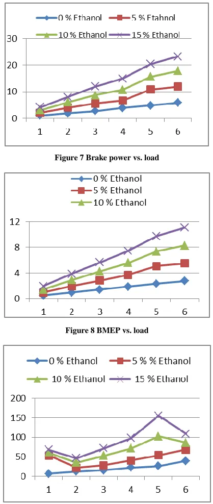
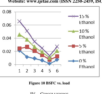
The performance has been checked for the SI engine by keeping speed of the engine constant and varying the load on the engine. The figure 7 to 10 shows the variation in various parameters of the engine with varying load. This shows that as the load on the engine increases, Brake power, BMEP and thermal efficiency of the engine increases.
[image:6.612.339.548.161.655.2]15 % of ethanol gives better performance as compare to other blends but BSFC is minimum for 0 % ethanol.
Figure 7 Brake power vs. load
Figure 8 BMEP vs. load
[image:6.612.67.271.455.631.2]International Journal of Emerging Technology and Advanced Engineering
Website: www.ijetae.com (ISSN 2250-2459, ISO 9001:2008 Certified Journal, Volume 6, Issue 8, August 2016) [image:7.612.68.275.122.313.2]243
Figure 10 BSFC vs. load
IV. CONCLUSIONS
Following conclusions are pointed out from the SI engine testing and theoretical results are found out by using theoretical formulae for comparison.
1. Adding ethanol to gasoline will lead to a leaner better combustion. The oxygen enrichment generated from ethanol increased the oxygen ratio in the charge and lead to lean combustion.
2. It is experimentally demonstrated that adding 5-15% ethanol to the blends led to an increase in the engine brake power, torque and brake thermal efficiency and volumetric efficiency since ethanol provides better combustion properties as compared with gasoline. 3. Experimental demonstration also reveals that the adding
5-15% ethanol results in decrease of the brake specific fuel consumption.
4. Up to 15% ethanol-gasoline blends can be used in spark ignition engines without any major modifications to the default system.
5. For usage of greater than 15% ethanol-gasoline blend in the engine, some modifications are required, like piston-cylinder material, air-fuel system, etc.
6. The results obtained with presented model are in acceptable agreement with those experimental and theoretical ones.
REFERENCES
[1] C. Ananda Srinivasan and C.G. Saravanan, “Study of combustion characteristics of a SI engine fuelled with ethanol and oxygenated fuel additives”, Journal of Sustainable Energy & Environment, vol. 1, 2010, pp.1-8.
[2] Keith O, Trevor C, “Automotive fuels reference book”, 2nd Edition, New York: SAE, 1995, pp.1.
[3] M. Al-Hasan, “Effect of ethanol-unleaded gasoline blends on engine performance and exhaust emissions”, Energy conversion and management, vol. 44, 2003, pp. 1547-61.
[4] Urban Laufenberg, Journal of best WP3 Low blends Final report, Sekab Biofuels & Chemicals, March 2010, pp.14-18.
[5] Engine manual, Niyo engineers pvt. Ltd. pp.1-78.
[6] V. ganeshan, “Internal combustion engines”, 3rd edition, Tata McGraw-Hill publications Delhi, March 2008, pp. 7-8,186-190,196-197.
[7] http:/www.wikipedia.org/SIengine
[8] R.K. Rajput, “A textbook of automobile engineering”, 3rd edition, Laxmi publications, 2009, pp.51-57, 116-118.
[9] Domkundwar, “A course in thermal engineering”, 5th edition, dhanpat Rai and Co., 2001, pp.12.1-12.40.
[10] Shane Curtis, Mark Owen, Terrence Hess and Scott Egan, “Effect of Ethanol Blends on a Spark Ignition 4-Stroke Internal Combustion Engine”, December 5, 2008, pp.1-10.
[11] Mohammad waspi bin kassim krismaran, “Influence of ethanol in spark ignition engine fuel consumption”, November 2009, pp.4-5, 15-24.
[12] UlrikLarsen, TroelsJohansen, EsperSchramm, “Ethanol as a Fuel for Road Transportation”, Technical University of Denmark, May2009, pp. 29-31.
Acknowledgement