International Journal of Emerging Technology and Advanced Engineering
Website: www.ijetae.com (ISSN 2250-2459, ISO 9001:2008 Certified Journal, Volume 8, Issue 3, March 2018)
11
The Learning Architecture of FPGA Based on CMAC Coding
Schemes Programed by VHDL
Ted Tao
Department of Computer and communication Engineering, Taipei City University of Technology and Science, Taipei, Taiwan
Abstract—Traditional hardware memory cannot generalize
information or learn information from neighbour memory, because its data equals either 0 or 1 in traditional hardware memory. Many software neural networks and fuzzy algorithms can solve above problems, but their processes are quite complicated for constructing hardware structure. In this paper, a simple hardware memory structure with learning ability and generalizing ability implemented by FPGA is proposed to solve above problems. The hardware memory includes two parts: (1) the proposed hardware memory structure is implemented by FPGA; (2) the CMAC coding schemes is programed by VHDL. The CMAC coding schemes written in VHDL is utilized to program FPGA as the hardware memory. Finally, the examples of image reconstruction illustrate the good learning effects of the proposed schemes.
Keywords—CMAC; FPGA; VHDL; hardware memory, and image reconstruction.
I. INTRODUCTION
The data of memory equals either 0 or 1 in traditional hardware memory, so it cannot learn or generalize from neighborhood to produce related information. The Very high speed integrated circuit Hardware Description Language (VHDL) [1, 17] is utilized to program Field Programmable Gate Array (FPGA) [2, 3, 18] as the structure of Cerebellar Model Articulation Computer (CMAC) [4, 5] in this paper, so that it becomes the hardware memory, which will have learning and generalizing ability [6].
The CMAC was firstly proposed by J. S. Albus in 1975 [4, 5], which can be seen as an associative memory neural network based on a look-up table method. There are several advantages including local generalization [6], good learning capacity, and rapid learning convergence [7-9]. They are easy to implement in automatic control [10-12] and signal processing [13-16]. However, the use of software CMAC networks in above literature spends more time to learn than the hardware coding method does. If the neural networks can be coded by firmware learning schemes, it will save lots of time in the control or image process.
In this paper, the CMAC coding scheme applied on FPGA as the hardware memory is proposed such that it can
quickly learn neighbour information. The examples of
image reconstruction illustrate the good learning effects of the proposed schemes. The hierarchical CMAC [13, 14] is also employed in the image reconstruction process. A coarse image is sent to the receiver by few sampled data, and then the image quality can be gradually improved from more sampled data by the request of the receiver. In other words, the receiver recognizes the image content at an early stage, and then decides whether further transmission is necessary to get high quality image. Consequently, transmission time can be saved. Experimental results demonstrate the proposed method can get high compressive ratio and higher PSNR after reconstruction.
This paper is organized as follows. After the introduction section, a two-dimension CMAC is introduced in Section II. CMAC coding procedure on FPGA by VHDL will be proposed in Section III. The learning architecture of FPGA based on CMAC networks is then discussed in section IV. Hierarchical CMAC networks for image compression and reconstruction on FPGA are provided in section V. Experimental results are shown in section VI to demonstrate the good learning effectiveness of the proposed methods. Finally, Section VII concludes this paper.
II.TWO-DIMENSION CMAC
International Journal of Emerging Technology and Advanced Engineering
Website: www.ijetae.com (ISSN 2250-2459, ISO 9001:2008 Certified Journal, Volume 8, Issue 3, March 2018)
12
Be aware that only the blocks on the same floor can be combined to form a hypercube. In other words, the hypercubes such as Af and Fk do not exist. Therefore, there are 100 hypercubes in this two- dimensional CMAC structure. When each input vector is specified, four hypercubes from the four floors are addressed. For example input vector v=(9,9) maps to Cc, Hh, Mm, and Rr four hypercubes. Note that these 100 hypercubes can be used to distinguish different weights of 289 input vectors. We also find that each hypercube shares data with neighbour input vectors, so there will not be any blocking effect.
In general, let v=(x,y) be the considered input vector and
) (j v
w be the stored data in the jth floor hypercube which is
mapped by input vector v, and the number of the floors of
CMAC be K. Then the output value g(x,y) can be computed in the following equation:
K j j v w y x g 1 ) ( ) , (. (1)
Since each input vector addresses exactly K hypercubes, only those data are used in the equation (1) for each input vector. Because the output value g(x,y) is generated from the CMAC hypercubes, the data of hypercubes need to be modified by the error e(x,y) that is the difference between the destined value d(x,y) and output value g(x,y) in the
learning process. The updating algorithm for
w
v(j) isdefined by the following equations:
K j y x e K u w w old j v new j
v( ) () ( , ); 1,2,, , (2)
) , ( ) , ( ) ,
(x y d x y g x y
e , (3)
where u is a learning rate in the learning process. According to reference [9], if 0u2 is true, then the above learning algorithm will converge, which is set to be one in this paper. Suppose that there are N states to be distinguished for each dimension, and K floors in CMAC.
Then there are 2
)] / ) 1 ((
[ceil Nj K hypercubes in the j-th floor, where the function ceil(x) rounds the elements of x to the nearest integer towards infinity. Thus the total number of hypercubes in a CMAC is described in the following equation: 2 1 )} / ) 1 (( {
K jm ceil N j K
N
. (4)
It is seen that there are only Nm hypercubes needed to distinguish 2
N inputs. The significant property of CMAC is
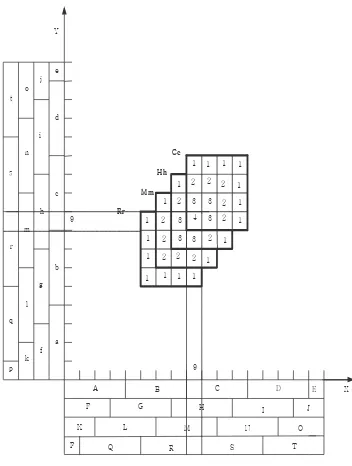
that the learning algorithm changes the output values for the nearby inputs. Therefore similar inputs lead to similar output even for unlearned inputs. This property is called generalization, which is of great use in the CMAC based coding. Moreover, we can control the degree of generalization by changing the size of K. The larger K is, the wider the generalization region is. The generalization region of a CMAC with K=4 is shown in Figure 1. If a value d(9,9)=4 is given as the destined weight of input, and then the input data maps to four hypercubes denoted by Cc, Hh, Mm and Rr, and four weights stored in the hypercubes are updated by Equations (1) and (2). Let the initial values of all weights be zero, then the error e(9,9) equals 4 before learning. The neighbour weights of the input vector v=(9,9) including itself will be all updated, and their values become “4‖, ―3‖, ―2‖, and ―1‖. More precisely, the outputs indicated by ―4‖, ―3‖, ―2‖, and ―1‖ are updated by (4ue/4), (3ue/4), (2ue/4), and (ue/4), respectively. The error e is e(9,9) which is the difference between the destined value d(9,9) and output value g(9,9) before the updating. We find that the neighbour outputs are changed even for unlearned input after updating by the CMAC learning algorithm, which is called generalization property. The generalization property of CMAC will be used to compress image data in later sections.
A B C D E X
Y
F G H I J
K L M N O
P Q R S T
a b c d e f g h i j k l m n o p q r s t Rr 9 9 4
2 3 3 3 2 3 3 3 1 2 2 2
2 2 1 2 2 2 2 2 1 1 1 1 1 1 1 1
[image:2.612.342.518.459.692.2]1 1 1 1 1 1 1 1 Cc Hh Mm
International Journal of Emerging Technology and Advanced Engineering
Website: www.ijetae.com (ISSN 2250-2459, ISO 9001:2008 Certified Journal, Volume 8, Issue 3, March 2018)
13
III. CMACCODING PROCEDURE ON FPGABY VHDL
A. The addressing function for CMAC coding procedure
In the traditional CMAC networks, the updating algorithm must go through the input vector to address hypercubes whose weights will be updated. Here, we propose an addressing function to code those addressed hypercubes. In our research, the addressing vector vi is
used to simultaneously generate the indices of K’s
addressed hypercubes. The data input mapping and output mapping through the addressing vector vi( ,x yi i) can be defined as follows:
(1) the input mapping ( , )
Dv x yi i iM, and
(2) the output mapping M wvi(j) G.
D is the domain of the input vector ( ,d x yi i); the index i means the i-th level input of d(x,y); the addressing vector
i
v maps the input signal ( ,d x yi i) into K’s hypercubes in
memory cell domain M; the weight wvi( )j is the j-th layer hypercube mapped by vi; G is the output domain; and the output ( ,g x yi i) equals summation of K’s weights mapped
by vector vi . Mapping the input signal to associative
memories ( DM) can be regarded as the encoding
process, and the mapping from the mapped memories (or
hypercubes) to the output value ( MG) can be regarded
as the decoding process. In our approach, the addressing vector vi is used to simultaneously generate the indices of K’s addressed hypercubes. Take a two-dimension CMAC network as an example, and there are N discrete units (or states) to be distinguished in each dimension. If there are K layers in a CMAC network, it needs only
m
N hypercubes to
distinguish 2
N pixels as described in equation (4). Now, consider a signal ( ,d x yi i) representing the quantized value
of the input vector ( , )x yi i , the variable xi maps into block ( )i
a x in x-axis, the variable yi maps into block ( )a yi in y-axis as equation (5). The function floor(x) rounds the elements of x to the nearest integers towards minus infinity.
) / ) 1 (( )
(x floor x j K
aj i i ,
) / ) 1 (( )
(y floor y j K
aj i i , for j = 1,2, … K. (5)
Then the addressing function v ji( ) can be generated from the following function:
] 1 ) / ) 1 (( [ ) ( ) ( )
(j a x a y floor N j K
vi j i j i
2 ] 1 ) / ) 1 (( [ ) 1 (
j floor N j K , for j = 1,2, … K. (6)
With this addressing functionv ji( ), N2 states can be mapped into Nm hypercubes. When a signal ( ,d x yi i) is quantized, the addressed hypercubes can be obtained directly with the above addressing function. Thus, the required data extraction or data updating can be performed with those hypercubes directly both in the encoding process and the decoding process. After proposing the coding process, we will use VHDL to program CMAC addressing functions on FPGA in Part B.
B. CMAC coding procedure programed by VHDL
The addressing function coded by a four layers two-dimension CMAC is discussed in this section. Because the CMAC addressing function is programmed by VHDL on hardware FPGA, its coding time will be much shorter than that in software CMAC. There are three main parts in the VHDL program: (1) the library part includes program libraries and packages; (2) the entity part defines the names and the data structure of the input and output ports; (3) the architecture part defines the names and the data structure of signals and their logical actions on the FPGA. The procedure of CMAC addressing function is included in the architecture part, which is described in Figure 2, which will be discussed it in next paragraph.
In CMAC coding procedure, there are 17 discrete units for each dimension in a 4-layer CMAC, which is programed by VHDL in Figure 2. Note that the function floor(x) does not need to apply in VHDL because all the signals and variables are defined as integer which already has floor(x) function as shown on line 29~32 in Figure 2. According to Equation (5), the input vector maps into blocks xLjaj(xi)in x-axis as shown on line 34~37, and it
maps into blocks yLjaj(yi)in y-axis for layer j=1~ 4 as
shown on line 38~42 in Figure 2. Take the value of blocks into Equation (6), and then the indexes of mapped hypercubes addrjvi(j)can be gotten. The four address are addr1, addr2, addr3, and addr4 as shown on line 42~45 in Figure 2, which are indexes values of mapped hypercubes in CMAC. The vector waveforms of four address (or indexes) are shown in Figure 3. For the same example in section II, the input vector maps to four of hypercubes (Cc, Hh,, Mm, and Rr), whose addresses are
12 ) 1 (
International Journal of Emerging Technology and Advanced Engineering
Website: www.ijetae.com (ISSN 2250-2459, ISO 9001:2008 Certified Journal, Volume 8, Issue 3, March 2018)
14
Figure 2. The CMAC addressing function programmed by VHDL on FPGA
Figure 3. The four indexes of hypercubes coded by input vector on FPGA.
IV. THE LEARNING ARCHITECTURE OF FPGA
BASED ON CMAC
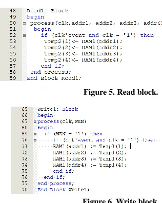
The learning architecture of FPGA based on CMAC networks written in VHDL will be proposed in this section. The learning architecture of FPGA includes four parts: (1) the definitions of signals, variables, and type are described on line 19-27 in Figure 4; (2) CMAC coding procedure is described on line 28-45 in Figure 2; (3) the read block is described on line 48-59 in Figure 5; (4) the write block is described on line 65-78 in Figure 6. Finally, the program of learning architecture itself is described on line 18-82 in Figure 4.
The memory cells (hypercubes in CMAC) must be defined as RAM on FPGA, so they should be typed as an array on Line 20, which are announced simultaneously to be shared variables on Line 21 in Figure 4 for reading and writing, whose initial values are set to be zero in VHDL. The Read and Write blocks are described in Figure 5-6. Consider the synchronization of input data, the positive edge trigger should be applied on line 52 in Figure 5 and on line 70 in Figure 6. Besides, the write-enable (WEN) is also applied in Write block for writing data into memory cells as shown on line 69 in Figure 6. Finally, the updating algorithm as equation (2-3) programed by VHDL for learning architecture of FPGA is described on 60-64 in Figure 4. The output value g(x,y) as equation (1) can be programed by VHDL on 79-81 in Figure 4.
[image:4.612.326.484.338.536.2]Figure 4. Learning architecture of FPGA programed by VHDL.
Figure 5. Read block.
Figure 6. Write block.
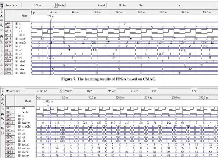
The learning results of FPGA based on CMAC is shown in Figure 7. The input vectors and data are
105 ) 0 , 9 (
1
v , v2(9,1)79 , v3(9,2)203 , v4(9,3)140 ,
100 ) 4 , 9 (
5
v ,v6(9,5)62,v7(9,6)177 andv8(9,7)182
separately. The initial values of memory cells (or hypercubes in CMAC) are set to be zero. When the first input v1(9,0)105 maps into four hypercubes, their indexes
International Journal of Emerging Technology and Advanced Engineering
Website: www.ijetae.com (ISSN 2250-2459, ISO 9001:2008 Certified Journal, Volume 8, Issue 3, March 2018)
15
When the second input v2(9,1)79 maps into four hypercubes, their indexes are (2, 27, 52, and 83). There is only one index (83) is different from first input, so its output already has initial value 78 in reading process. The weights of four mapped hypercubes are same after learning, because the error (79-78=1) distribute to four mapped hypercubes (integer(1/4)=0) become zero because memory variables are defined as integer in writing process. When the third input v3(9,2)203 maps into four hypercubes,
their indexes are (2, 27, 57, and 83). It is found that only one index (57) have not been mapped, so only other three hypercubes have values in their weights, and the four weights of mapped hypercubes are (26, 26, 0 , and 0), and then the sum of four mapped weighs become 52 in the reading process.
[image:5.612.83.532.342.666.2]The error between destination and output is 151 (203-52=151) in reading process, it (integer(151/4)=37) will add into four mapped hypercubes, the weights of four mapped hypercubes become (63, 63, 37, and 37) separately. The other learning processes are same, and the learning results are shown in Figure 7. If all hypercubes need to be trained, every data should be trained through traditional learning processes. It wastes training time, so we propose one time learning method as shown in Figure 8(a)-8(b), where all indexes of hypercubes from 1 to 100 can be chosen through only 25 (1/K2) data need to be trained (K=4 is the number of Layers). The method is that we only choose every K data in each dimension for one time learning method, so all indexes of hypercubes have been chosen at least one time. Because all hypercubes have been trained, all output mapped by any input vector will have related information.
Figure 7. The learning results of FPGA based on CMAC.
International Journal of Emerging Technology and Advanced Engineering
Website: www.ijetae.com (ISSN 2250-2459, ISO 9001:2008 Certified Journal, Volume 8, Issue 3, March 2018)
16
Figure 8(b). There are 100 chosen indexes in one time learning method, and the other 48 indexed are in this waveform.
V.HIERARCHICAL CMACNETWORKS FOR IMAGE
COMPRESSION AND RECONSTRUCTION ON FPGA
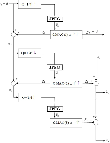
The block diagram of hierarchical CMAC for image compression and reconstruction is shown in Figure 9. The hierarchical contains m’s levels (here m is set to be 3 in this paper), and each level is composed of two processes: the down sampling process (the sample ratioQ1/ 4m) and the reconstruction process reconstructed by CMAC(m). Note that the reconstruction process is done by independent CMAC networks for different levels, which ensures that later information can still be updated but not corrupt the learned information in early levels of hierarchical CMAC networks. The original image data are used as initial error codes e0 in the first level, the error codes are selected every
2m(m=3 in this paper) units in each dimension (down
sample data are m
4 /
1 of whole image data), and then the sampled and compressed codes eˆ0 information is utilized to update the first level CMAC(1) in hierarchical CMAC networks. The receiver will get the reconstructed image data g1 in the first level of hierarchical CMAC networks.
The original data e0 minus reconstructed data g1 are
[image:6.612.79.535.130.291.2]simultaneously sent to next level as the second level’s error code e1. The reconstruction processes of the second level of hierarchical CMAC networks are same as the first level does, but down sampling ratio are different in different levels. The down sample ratio equals 1/ 4m i 1 in the i-th level. Let an independent CMAC(i) be the i-th level CMAC of hierarchical CMAC networks, so weights of hypercubes will not interfere between different levels. It ensures that later information can still be updated but not corrupt the learned information in early levels of hierarchical CMAC networks.
Figure 9. The block diagram of hierarchical CMAC networks.
Let the i-th level CMAC(i) include Ki layers, then the number of hypercubes used in i-th level can be computed by the following equation, where N is the number of pixels in each dimension.
2 1
1
[ (( 1) / )] ; 2 ; 1, 2, , 1
i
K
m i
i i i
j
N ceil N j K K i m
[image:6.612.333.554.313.599.2]International Journal of Emerging Technology and Advanced Engineering
Website: www.ijetae.com (ISSN 2250-2459, ISO 9001:2008 Certified Journal, Volume 8, Issue 3, March 2018)
17
In the reconstruction process, the i-th level’s CMAC(i) has Ki layers, and the sampled pixels are each Ki points
along each dimension in this level. It is impossible to interfere with each other for CMAC learning because every hypercube is selected just one-time, thus it can update all weights of CMAC in the same level without corrupting learned information. The hypercubes of different level CMAC networks are independent, so the weights in different level will not interfere with each other too. Each pixel maps toKi’s hypercubes, so the data of neighbour pixels can be generated even then they haven’t been trained. The error codes are transmitted to the next level, so the PSNR can be improved in the later level. This is the reason why the hierarchical CMAC networks can gradually improve the quality of reconstructed image. The algorithm is described in the following equations:
0( , ) ( , );
e x y d x y (8)
), , ( ) , ( ) ,
(x y e 1 x y g x y
ei i i i1, 2, ,m1; (9)
( ) ( ) ˆ ( , ),
i i
new old
v j v j i i i
i u
w w e x y
K
i1, 2, ,m1; (10)
1 ( )
1
( , ) , 2 ,
i
i
K
m i
i v j i
j
g x y w K
j1, 2, ,Ki; (11)It takes only 1/Ki division for per pixel, because the number of sampled error codes ˆ ( , )e x yi i i in Equation (10) is
2
1/Ki of original image data in i-th level of hierarchical
CMAC networks. Besides, the number Ki is power of 2, it
is performed with a shift operation on FPGA, which takes very little time for hardware shift operation, and so the computation time of division almost can be regardless. In Equation (11), it costs only Ki’s additions for per pixel in
the i-th level of hierarchical CMAC networks, so it takes
very little to get output data. The data transmitted in the hierarchical CMAC networks are described in the following equations:
) , ( ) ,
( 1
1 x y g x y
h (12)
1
( , ) ( , ) ( , ), for 2,3, , .
i i i
h x y g x y h x y i m (13)
Equation (13) needs only one addition for per pixel to improve the PSNR of reconstructed image in each level.
We take a three level hierarchical CMAC as an example.
It takes only
143
142
14
of original image datawithout compression to transfer to the receiver.
The receiver use only three add operations to get the image data, if the divisions are regardless on FPGA. Consequently, the CMAC Coding Schemes applied on FPGA take lesser time than the tradition software CMAC does. Besides, the hierarchical CMAC can compose JPEG, and then it needs few volume of original data for image reconstruction in our experiments.
VI. EXPERIMENTAL RESULTS
In order to measure the quality of the reconstructed image, the peak signal to noise ratio (PSNR) is defined in (14), where the grey level of image ranges from 0 to 255. We take a 512x512 size standard ―Lena‖ as an original image, whose grey levels equal 256 and the data volume
equals 258KB. The volume of JEPG image becomes 32KB,
whose PSNR equals 37.81dB as shown in Figure 10.
255
PSNR=10 log( ) dB
MSE
(14)
There are three levels (m=3) in the hierarchical CMAC networks in Figure 9. In order to increase compression ratio, the JPEG method is also applied to the proposed hierarchical CMAC networks. The proposed method not only can increase compressive ratio during transmission, but also can improve PSNR in the high level hierarchical CMAC networks. The level of hierarchical CMAC networks is set to be 3 and learning rate u is set to be 1 in our experiments.
In the first level the original image data are used as initial error codes e0, through down sampling and JPEG
International Journal of Emerging Technology and Advanced Engineering
Website: www.ijetae.com (ISSN 2250-2459, ISO 9001:2008 Certified Journal, Volume 8, Issue 3, March 2018)
18
In the third level, error codes (e2 e1g2) through down sampling and JPEG compression processes become
codes eˆ2, which are transmitted to the receiver. Its size (128x128) is 1/4 of original image and the data volume equals 11KB as shown in Figure 13(a). Through reconstruction processes of CMAC (3), the reconstructed error codes (
3
g ) add to the second level’s reconstructed
image codes (h2) become codes (
2 3
3 g h
h ). It is the
output image of the third level, whose PSNR equals 31.34dB as shown in Figure 13(b).
It is obvious that the quality of the reconstructed image
is improved in the higher level hierarchical CMAC
networks. The total volume of transmitted data in three
level hierarchical CMAC networks equals 17KB
(2KB+4KB+11KB), which is much less than the volume (32KB) of original JPEG image as shown in Figure 10. In addition, if the quality of reconstructed image is not satisfied, then an additional level can be utilized to improve PSNR again in next paragraph. Although the third level’s PSNR (31.34dB) is lower than that (37.81dB) of the original JPEG image. It is hard to distinguish the quality between the original JPEG image in Figure 10 and the final reconstructed image in Figure 13(b) by naked eyes. It can be found that the total volume of transmitted data (17KB) in three level hierarchical CMAC networks is almost half of the volume of original JPEG image (32KB) as shown in Figure 10.
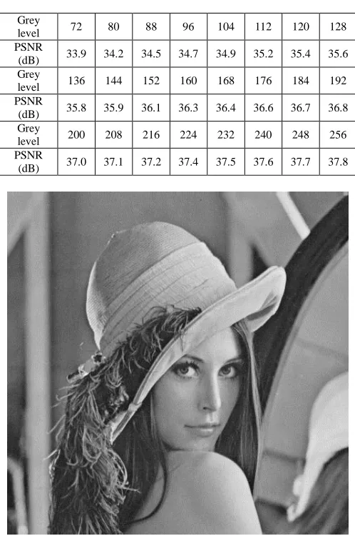
It still can be improved by adding additional compressed error codes to the third level’s reconstructed codes, whose PSNR will be improved. Note that all the error codes are transmitted in the additional level, so they need neither the down sampling process nor CMAC reconstruction. The value of error codes is smaller in the additional level, so the lesser grey level range is needed. The grey level can be set to lower in order to get higher compression ratio. In additional level’s compressive procedures (JPEG is used in this paper), the grey level ranges (from 72 to 256) are set to get compressive image, and their volumes and PSNR of reconstructed images are shown in Table I. We can conclude that the lesser grey level range is, and the smaller volume of compressed image is during the compressive procedures. But the more grey level range is, and the higher PSNR of reconstructed image is.
TABLE I
THE DIFFERENT GREY LEVELS AND RECONSTRUCTED
IMAGE PSNRS IN THE ADDITIONAL LEVEL
Figure 10. The volume of JEPG image is 32KB, whose PSNR equals 37.81dB.
VII.CONCLUSIONS
The CMAC coding schemes programmed by VHDL on FPGA as the hardware memory is proposed in this paper such that it can quickly learn or generate neighbour information from few sampled data. The hierarchical CMAC and JEPG are both employed in the image reconstruction examples.
Grey
level 72 80 88 96 104 112 120 128 PSNR
(dB) 33.9 34.2 34.5 34.7 34.9 35.2 35.4 35.6 Grey
level 136 144 152 160 168 176 184 192 PSNR
(dB) 35.8 35.9 36.1 36.3 36.4 36.6 36.7 36.8 Grey
level 200 208 216 224 232 240 248 256 PSNR
[image:8.612.319.568.170.545.2]International Journal of Emerging Technology and Advanced Engineering
Website: www.ijetae.com (ISSN 2250-2459, ISO 9001:2008 Certified Journal, Volume 8, Issue 3, March 2018)
19
A coarse image is sent to the receiver, and then the image quality can be gradually improved from more sampled data by the request of the receiver.
In other words, the receiver recognizes the image content at an early stage, and then decides whether further transmission is necessary. Consequently, computation and transmission time can be saved.
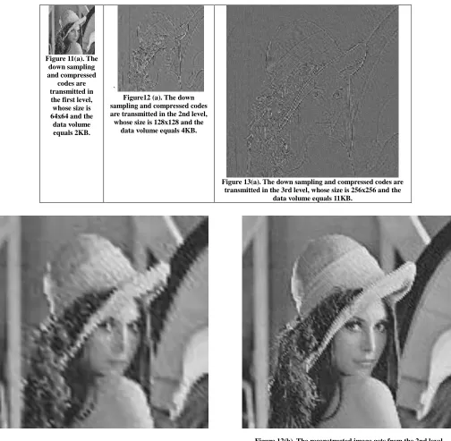
Figure 11(b). The reconstructed image h1 gets from the first level hierarchical CMAC, and its PSNR equals 23.29dB.
Figure 12(b). The reconstructed image gets from the 2nd level hierarchical CMAC networks, and its PSNR equals 26.82dB. Figure 11(a). The
down sampling and compressed
codes are transmitted in the first level, whose size is 64x64 and the
data volume equals 2KB.
`
Figure12 (a). The down sampling and compressed codes are transmitted in the 2nd level, whose size is 128x128 and the
data volume equals 4KB.
Figure 13(a). The down sampling and compressed codes are transmitted in the 3rd level, whose size is 256x256 and the
[image:9.612.54.558.182.675.2] [image:9.612.51.308.186.653.2]International Journal of Emerging Technology and Advanced Engineering
Website: www.ijetae.com (ISSN 2250-2459, ISO 9001:2008 Certified Journal, Volume 8, Issue 3, March 2018)
20
Figure 13(b). The reconstructed image gets from the 3rd level hierarchical CMAC networks, and its PSNR equals 31.34dB.
Experimental results demonstrate the reconstructed image can get higher PSNR in higher level of hierarchical CMAC networks. Meanwhile, some advantages proved by the proposed method are listed as follows:
(a)The Based on CMAC hardware FPGA memory is
proposed so it can quickly reconstruct image.
(b) A novel coding method proposed in hierarchical
CMAC networks makes one-shot training possible, and
only 1
1/ 4m i (same as sample ratio) of computation is needed during compression and reconstruction processes in the i-th level of hierarchical CMAC networks. (c)Error codes can be normalized into different grey level
ranges, which makes different compressive ratio and image quality.
(d)The coarsest reconstructed image can be quickly
produced, and the image quality can be improved in the higher level of the hierarchical CMAC networks. (e)Due to the generalization ability of CMAC networks,
the sizes of all reconstructed images are equal to the original image sizes.
REFERENCES
[1] IEEE Standard VHDL Language Reference Manual, IEEE Std. 1076-1987, IEEE Press, 1988.
[2] Betz, V., Rose, J., and A. Marquardt, Eds., Architecture and CAD for Deep-Submicron FPGAs, Norwell, MA: Kluwer, 1999. [3] Ho, C. H., Yu, C., Leong, P., Luk, W., and Wilton, S. J. E.
―Floating-point FPGA: Architecture and modeling,‖ IEEE Trans. on VLSI Syst., vol. 17, no. 12, pp. 1709–1718, Dec. 2009.
[4] Albus, J. S. ―A new approach to manipulator control: The cerebellar model articulation controller (CMAC),‖ ASME Journal of Dynamic Systems, Measurement, and Control, pp. 220-227, 1975.
[5] Albus, J. S. ―Data storage in the cerebellar model articulation controller (CMAC),‖ ASME Journal of Dynamic Systems, Measurement, and Control, pp. 228-233, 1975.
[6] Gonzalez-Serrano, F. J., Figueiras-Vidal, A.R., and Artes-Rodriguez, A. ―Generalizing CMAC architecture and training,‖ IEEE Trans. on Neural Networks, vol. 9, no. 6, pp. 1509-1514, 1998.
[7] Wong, Y. F. and Sideris, A. ―Learning convergence in the model articulation controller,‖ IEEE Trans. on Neural Networks, vol. 3, no.1, pp.115-121, 1992.
[8] Wang, L. X. ―A supervisory controller for fuzzy control systems that guarantees stability,‖ IEEE Trans. on Automatic Control, vol. 39, no. 9, pp.1845 – 1847, 1994.
[9] Lin, C. S. and Chiang, C. T. ―Learning convergence of CMAC technique,‖ IEEE Trans. on Neural Networks, vol. 8, no.6, pp.1281-1292, 1997.
[10] Tao, T. and Su, S. F. ―CMAC-Based previous step supervisory control schemes for relaxing bound in adaptive fuzzy control,‖
Applied Soft Computing Journal, pp. 5715-5723, vol. 11, no. 8, 2011.
[11] Tao, T., Wei, C. P. and Chen, L. Y. ―The auxiliary CMAC applied to online tuning robust fuzzy controllers,‖ in Proc. the 2008 IEEE International Conference on Fuzzy Systems, Hong Kong, pp.783~789, June 2008.
[12] Tao, T., Lu, H. C., and Su, S. F. ―Robust CMAC control schemes for dynamic trajectory following‖, Journal of the Chinese Institute of Engineers, vol. 25, no. 3, pp.253-263, 2002.
[13] Iiguni, Y. ―Hierarchical image coding via cerebellar model arithmetic computers,‖ IEEE Trans. on Image Processing, vol. 5, no. 10, pp. 1393-1401, 1996.
[14] Lu, H. C. and Tao, T. ―Closed-loop method to improve image PSNR in pyramidal CMAC networks,‖ International Journal of Computer Applications in Technology, vol. 5, no. 1, pp. 22-29, 2006. [15] Tao, T. and Ding, C. C. ―Differential codes transmitting in
pyramidal CMAC networks,‖ in Proc. the 2007 IEEE International Conference on Systems, Man and Cybernetics, Taipei, Taiwan, pp. 3330-3335, 2007.
[16] Tao, T. and Su, S. F. ―Moment Adaptive Fuzzy Control and Residue Compensation,‖ IEEE Transactions on Fuzzy Systems, vol. 22, no. 4, pp. 803-816, Aug. 2014
[17] R. D. Yershov, D. S. Yakosenko, and S. I. Yatsenko, ―A scalable VHDL-Implementation technique of the binary encoder structure into FPGA,‖ Lviv, Ukraine, pp. 74-79, Oct. 2017.
[image:10.612.48.292.131.374.2]