International Journal of Emerging Technology and Advanced Engineering
Website: www.ijetae.com (ISSN 2250-2459, ISO 9001:2008 Certified Journal, Volume 4, Issue 6, June 2014)
830
A Comparative Study of Coolants Based on the Cooling
Time of Injection Molding
Rahul Vashisht
1, Arjun Kapila
21,2
M.Tech, Delhi Institute of Tool Engineering, Okhla, Delhi, India
Abstract—Injection molding consists of six major steps i.e. clamping, injection, dwelling, cooling, mold opening and ejection. Each step have an effect on the process parameters and cycle time. Cooling is an important stage which constitutes almost 60% time of the total cycle time. Thus in this paper, we aim to find out the effect of different coolants on the cooling time, mold temperature and part temperature. An aim is also to find out substitute of water, being used as coolant. Water has an adverse effect on cooling channel with the respect of time. We identified the coolants used in the process and compared the same with the help of moldflow simulation software. The results are compared to find out the most effective coolant for the process.
Keywords—Injection Mold, Clamping, Cooling, Cycle time, Coolant, Mold Temperature, Par Temperature
I. INTRODUCTION
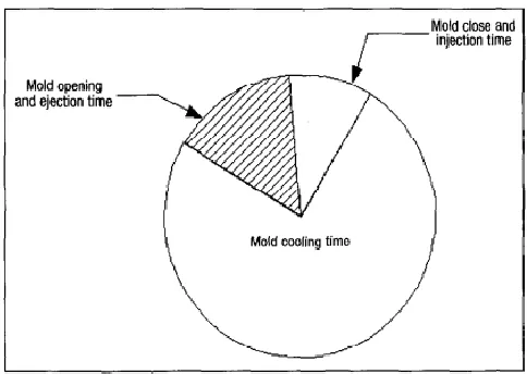
Injection molding is a method to obtain molded products by injecting plastic materials molten by heat into a mold, and then cooling and solidifying them. The method is appropriate for the mass production of products with complex shapes, and takes a large part in the area of plastic processing. The design of an optimal cooling system and operation conditions of the cooling process are very crucial to the injection molding process [1]. There are number of parameters during the injection molding related to cooling. In injection molding, the mold cooling time usually takes up to about 70%-80% of the time of the entire cycle. Figure 1shows the relation between mold cooling time and a molding cycle [2]. As far as mold cooling is concerned, mold engineers need to determine the following design parameters: cooling channel position, cooling channel type, cooling channel deployment and connections, length of cooling channel, flow rate of cooling and coolant used [3]. Generally water is used widely for mold cooling purpose. The major drawback of water is that it causes metal to rust. The boiling point of Clean water (H20) is 100 degrees Celsius or 212f, with all the salts like Magnesium, calcium and chlorine (in tap water) you can have it boil at less than 85°Celsius. These salts deposit after long use of water (same whitish stuff we seee at the bottom of kettles) and the deposits clog our mold cooling channels and stresses the line and pump.
[image:1.612.326.568.331.503.2]This leads to the failure of the cooling lines and effects the cooling efficiency. Also as the water boils it expands and also releases gases dissolved in it. Gas expansion due to heat is way more than liquid expansion, this expansion causes pressure build up. It can cause damage to the machine parts. Thus to avoid this a coolant with a solution to above said problem is necessary. However the cost of the coolant will be more compared to water but in long term it pays off with an increase in production and efficiency.
Figure 1 Relation between Mold Cooling Time and Molding Cycle
Thus an effort is put in this paper to find an effective and efficient coolant with same or superior results when compared to water. Cycle time is simulated for each coolant and part and mold temperature is noticed.
International Journal of Emerging Technology and Advanced Engineering
Website: www.ijetae.com (ISSN 2250-2459, ISO 9001:2008 Certified Journal, Volume 4, Issue 6, June 2014)
831
II. BASIC ASSUMPTIONS OF THE DESIGN OF INJECTION
MOLD COOLING CHANNELS
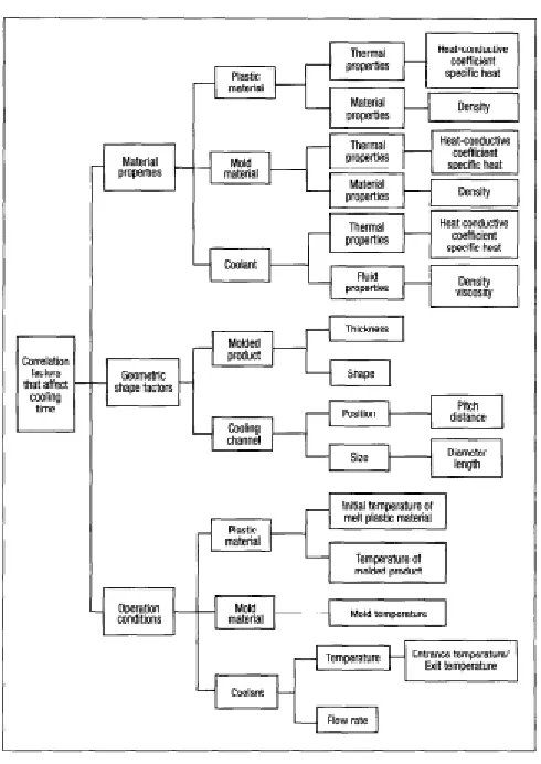
The objective of injection mold design is to reduce the cooling time. There are a number of factors affecting cooling time. Here, factors linked to cooling time are listed in brief in Figure 2 to serve as the basis of design considerations. These factors are described below [1]:
1. Thickness of molded product. The thicker the molded product, the cooling time will be longer.
2. Shape of the molded product. If the molded product has
a complex shape, then the cooling effect at some parts may be reduced, affecting the cooling time.
3. Quality of plastic material melt. Because different kinds of plastic materials have different thermal diffusivity, their thermal conductivity effects also differ. Plastic materials having a greater thermal diffusivity have greater thermal conductivity rates and require a shorter cooling time.
4. Injection temperature and ejection temperature. The higher the injection temperature, the longer the cooling time required. In contrast, the lower the ejection temperature, the longer the cooling time required. 5. Mold material. Because different metal material of the
mold have different thermal conductivity, their thermal conductivity effects also differ. Metals with a greater thermal conductivity conduct heat faster and require a shorter cooling time.
6. Number, position, and size of cooling channels. The design of cooling channels has a decisive effect on the overall cooling time. Generally speaking, the larger the number of cooling channels, the closer the cooling channels are to the molded product or the larger the channel diameter, the better the cooling effect and the shorter the cooling time.
7. Quality of coolant. Different coolants have different heat transfer coefficient, specific heat, density and viscosity, and thus, different heat transfer results. 8. Coolant flow rate and temperature. The coolant flow
rate must reach the turbulent flow to increase the heat transfer effect. Besides, the lower the coolant temperature, the shorter the cooling time.
The cooling stage involves very complicated issues. To simplify the process, the following assumptions are made in this study:
[image:2.612.324.569.130.476.2]1. Because changes of the physical properties of mold materials as a result of temperature and pressure are not significant, they are considered constants.
Figure 2 Factors Affecting Cooling Time
2.The energy released by the plastic materials is assumed to be completely absorbed by the coolant and mold material.
3.The temperature of the cooling channel wall is assumed
to be constant.
4.It is assumed that during the initial stage, both the mold and the plastic material have their own uniform temperature, and that the plastic material does not contain any solid part.
5.The inner pressure of mold cavity is assumed constant. Thus, the effect of pressure reduction at the boundary layer is ignored and the volume of plastic materials remains constant during the solidification process. 6.The solidification latent heat is calculated as part of the
specific heat, without considering the displacement of boundary layer.
International Journal of Emerging Technology and Advanced Engineering
Website: www.ijetae.com (ISSN 2250-2459, ISO 9001:2008 Certified Journal, Volume 4, Issue 6, June 2014)
832
8. The thermal effect derived from the crystallization process is ignored in this study.
9. Feeding system is not considered in the cooling
simulation only interaction with the cooling channel and component is considered.
III. COMPONENT AND COOLING CHANNEL
[image:3.612.55.285.265.530.2]The component in Figure 3 is used in the simulation process. A single cavity injection mold is considered for the same.
Figure 3 3D Model of the Component
Figure 4 Detail Model of the Component
Material: Acrylonitrile butadiene styrene Abbreviation: ABS
Molecular formula: (C8H8·C4H6·C3H3N) n Part weight: 14.2 grams
Elastic Modulus: 2240 Mpa Poissons ratio (v12): 0.392 Shear Modulus: 804.6 Mpa Wall Thickness: 2.5mm Melt Temperature: 220°C Mold Temperature: 50°C
Acrylonitrile butadiene styrene (ABS) is a common
thermoplastic. Its glass transition temperature is
approximately 105 °C (221 °F) [4].ABS is amorphous and
therefore has no true melting point.
The most important mechanical properties of ABS are impact resistance and toughness. A range of modifications can be done to increase impact resistance, toughness, and heat resistance. Changing the proportions of its components ABS can be prepared in different grades. Two major categories could be ABS for extrusion and ABS for injection moulding, then high and medium impact
resistance. Generally ABS would have useful
characteristics within a temperature range from −20 to 80 °C (−4 to 176 °F) [5].
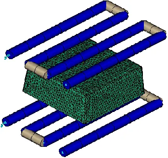
Cooling channel of Ø6 mm is used with the channel distance of 15 mm above and below the components. Figure 5 explain the placement of the cooling channels with respect to component. The cooling channels extends upto a distance of 25 mm beyond the part. Moreover the distance between the channel centers is taken as 15 mm. Coolant parameters for cooling simulation specified are:
Flow Rate – 20 lt/min
[image:3.612.361.535.414.577.2]Coolant Inlet Temperature – 25°C
Figure 5 Component and Cooling Channel Placement
International Journal of Emerging Technology and Advanced Engineering
Website: www.ijetae.com (ISSN 2250-2459, ISO 9001:2008 Certified Journal, Volume 4, Issue 6, June 2014)
833
TABLE 1
DIFFERENT COOLANT WITH THEIR PROPERTIES
S.
No Name
Density (g/cm3)
Specific Heat (J/kg-C)
Thermal Conductivity
(W/m-C)
1 Water 0.988 4180 0.643
2 Oil 0.836 2250 0.136
3 Ethyl
Glycol(Pure) 1.117 2382 0.249
4 Coolanol
45:Chevron 0.870 2050 0.1301
5
Ucon Heat Transfer Fluid
500: Union Carbide
0.977 2093 0.1547
6
Dowfrost HD/Glycol 75%-25%:
Dow Chemical
1.019 3929 0.4804
7 PG-1:
Multithem 0.836 2198 0.1263
8 IG-2:
Multithem 0.815 2323 0.1263
IV. MOLDFLOW SIMULATION
Simulation is the technology that can forecast the plastic flow inside the mold cavity. It gives us a close result of a process without manufacturing mold. It is used by the designer to solve various problems at design stage by forecasting the whole process. It's one of the most appreciated software by an injection mold designer. Moreover it generates 3D simulation that models the flow of resin material into a single or multi -cavity mold. With the support of mold flow analysis, engineers can obtain statistical data of the molding process before the mold is actually fabricated. The results obtained by the analysis helps the engineer/designer in selecting the optimum location for gate type, sprue and runner etc. The result obtained is accurate, economical and desired plastic parts with few trials and error/ rejection. Now we will simulate the cooling stage of injection molding with different coolants in successive trials.
A. Trial 1 Water
Water when used as the coolant, the cooling time from simulation came out to be 26.76 sec. Moreover the mold temperature came out to be 45.78°C and part temperature came out as 50.66°C.
B. Trial 2 Oil
Oil when used as the coolant, the cooling time from simulation came out to be 27.46 sec. Moreover the mold temperature came out to be 48.36°C and part temperature came out as 53.16°C.
C. Trial 3 Ethyl Glycol(Pure)
Pure ethyl glycol when used as the coolant, the cooling time from simulation came out to be 26.97 sec. Moreover the mold temperature came out to be 46.61°C and part temperature came out as 51.46°C.
D. Trial 4 Coolanol 45:Chevron
Coolanol 45: Chevron when used as the coolant, the cooling time from simulation came out to be 27.60 sec. Moreover the mold temperature came out to be 48.86°C and part temperature came out as 53.64°C.
E. Trial 5 Ucon Heat Transfer Fluid 500: Union Carbide
Ucon Heat Transfer Fluid 500: Union Carbide when used as the coolant, the cooling time from simulation came out to be 27.38 sec. Moreover the mold temperature came out to be 48.07°C and part temperature came out as 52.88°C.
F. Trial 6 Dowfrost HD/Glycol 75%-25%: Dow Chemical
Dowfrost HD/Glycol 75%-25%: Dow Chemical when used as the coolant, the cooling time from simulation came out to be 26.82 sec. Moreover the mold temperature came out to be 46.03°C and part temperature came out as 50.90°C.
G. Trial 7 PG-1: Multithem
PG-1: Multithem when used as the coolant, the cooling time from simulation came out to be 26.71 sec. Moreover the mold temperature came out to be 45.58°C and part temperature came out as 50.48°C.
H. Trial 7 IG-2: Multithem
IG-2: Multithem when used as the coolant, the cooling time from simulation came out to be 26.96 sec. Moreover the mold temperature came out to be 45.48°C and part temperature came out as 50.33°C.
International Journal of Emerging Technology and Advanced Engineering
Website: www.ijetae.com (ISSN 2250-2459, ISO 9001:2008 Certified Journal, Volume 4, Issue 6, June 2014)
834
After all the simulation being carried out, the result is formulated and compared.
V. RESULTS
TABLE 2 RESULT
Tr ial . No
Name
Cool Time (sec)
Mold Temperatu
re (°C)
Part Temperatu
re (°C)
1 Water 26.76 45.78 50.66
2 Oil 27.46 48.36 53.16
3 Ethyl
Glycol(Pure) 26.97 46.61 51.46
4 Coolanol
45:Chevron 27.60 48.86 53.64
5
Ucon Heat Transfer Fluid
500: Union Carbide
27.38 48.07 52.88
6
Dowfrost HD/Glycol 75%-25%:
Dow Chemical
26.82 46.03 50.90
7 PG-1:
Multithem 26.71 45.58 50.48
8 IG-2:
Multithem 26.96 45.48 50.33
Chart 1 Comparison of Cooling Time
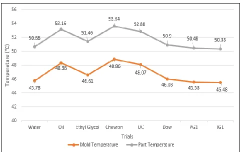
Chart 2 Comparison of Mold and Part Temperature
VI. CONCLUSION
As from the results we found out that PG-1: Multithem provides the best cooling time of 26.71 sec which is the lowest for all the coolant utilised. From chart one we easily found out that a difference of 0.89 sec came out which is very high when calculated in mass production. Moreover this coolant performed better than water and also the problems seen with water as coolant medium is eliminated with this coolant. This reduces the problems caused by the blockage of the cooling channel. Also the mold temperature and part temperature is also reduced marginally when compared to water, but over all a difference of about 3.38°C and 3.31°C was found out as in Chart 2. It is also noticed that the Coolanol 45 and oil proved out to be least effective coolant medium whereas PG-1 and IG-2 proved to be most effective.
REFERENCES
[1] Roasto, D.V. and Roasto, D.V. (1985), Injection Molding Handbook, New York: Van Nostrad Reinhold Co.
[2] Chow, W.H. (1999) C-mold for Design of Injection Guide. Taipei, Taiwan: Wen King Book Co., AC Technology.
[3] Zone-Ching Lin and Ming-ho Chou (2002), Design of the Cooling Channels in Nonrectangular Plastic Flat Injection Mold: Journal of Manufacturing Science, Vol.21/No.3
[4] Plastic Properties of Acrylonitrile Butadiene Styrene (ABS) Small table of ABS properties towards the bottom. Retrieved 7 May 2010. [5] Analysis of Plastic Flow in Two Plate Multi Cavity Injection
Mould for Plastic Component for Pump Seal BY Jagannatha Rao M B, Dr. Ramni
[6] R.G.W. Pye, “An Introduction, and Design Manual for the thermoplastic Industry,” 4th Edition, East West Press Pvt. Ltd., New Delhi, 2000.
[image:5.612.326.570.135.287.2]