International Journal of Emerging Technology and Advanced Engineering
Website: www.ijetae.com (ISSN 2250-2459, ISO 9001:2008 Certified Journal, Volume 4, Issue 2, February 2014)
105
Odd and Even Switching Pattern in PV Generation System
Coupled SHEPWM Inverter to Reduce Harmonics in Grid
Prof. D. Rajalakshmi
1, Dr. K. Geetha
2, M. Malathi
3 1Assistant Professor, 3PG scholar, EEE Department, Kumaraguru college of technology Coimbatore-641049 2Head of the department, Information technology Karpagam Institute of technology, Coimbatore- 641105
Abstract— In this paper grid connected photovoltaic generation system to mitigate the lower order harmonics by using SHE PWM inverter is discussed. In Renewable sources, solar photovoltaic system is more flexible and pollution free. Then SHE PWM inverter is used to maintain the output voltage with reduced selective harmonics ( 5th, 7th, 11th, 13th ). The system is proposed to reduce selective harmonics in the output using optimized SHEPWM inverter. The switching angle is calculated using GA Tool. The analysis can be done with grid connected photovoltaic system through SHE PWM inverter. The proposed design will be done by using Matlab simulation results can be observed.
Keywords— photovoltaic (pv) generation system, selective Harmonic Elimination- Pulse width modulation (SHE-PWM) inverter.
I. INTRODUCTION
The grid connected photovoltaic generation by using SHE-PWM inverter .Then PWM inverter is used to maintain the output voltage with system with reduced the lower order harmonics can be done reduced selective harmonics. The system is proposed to reduce selective harmonics in the output using optimized SHEPWM inverter. The analysis can be done with grid connected photovoltaic system through SHE PWM inverter. The improvement of power quality has been the major issue in power electronics [1]. The elimination of specific lower order harmonics improves the performance of voltage source inverter. The main classification of PWM techniques are carrier modulated PWM and Selective Harmonic Elimination based PWM [2]-[5]. In that SHE based PWM technique offers best solution. It has been dealt in enormous papers for single and three phase system [8]. This method can provide the highest quality output and offers several advantages compared to many modulation methods including low switching frequency[10]. It is
generallyaccepted that the performance of an inverter with
[image:1.612.351.537.247.385.2]any switching strategies, can be related to the harmonic contents of its output voltage.
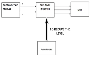
Fig 1: Block Diagram
II. PHOTOVOLTAIC ARRAY
International Journal of Emerging Technology and Advanced Engineering
Website: www.ijetae.com (ISSN 2250-2459, ISO 9001:2008 Certified Journal, Volume 4, Issue 2, February 2014)
106
III. BIPOLAR SWITCHING PATTERN
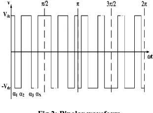
The switching pattern is of unipolar and bipolar type and this includes one level, two levels and three level waveform. For three phase inverters bipolar switching pattern shown in fig 1 is used to find the appropriate switching angles that include both odd and even angles. To eliminate N-1 harmonics completely from the inverter output waveform N switching angles have to be calculated in quarter period of waveform.
In this paper optimized switching angles are produced to eliminate the lower order harmonics such as 5th, 7th, 11th and 13th. By including both even and odd values of switching angles the harmonic content are much reduced. The output voltage equation of the inverter is
(1)
Whereas is the fundamental component and have to
be improved and is the even harmonics that are almost
zero and is the odd harmonics have to be eliminated.
[image:2.612.88.243.394.508.2]The range of switching angles should be between 0 to 90 degree.
Fig 2: Bipolar waveform
IV. GENETIC ALGORITHM
The genetic algorithn is a method for solving both constrained and unconstrained optimization problems that is based on natural selection, the process that drives biological evolution. The gentec algorithm selects individual in random from the current population to be parents and uses them to produce the children for the next generation. Over sucessive generations , the population ―evolves‖ toward an optimal solution.
The Genetic algorithm is used to solve a variety of optimization problems that are not well suited for standard optimization algorithms, including problems in which the objective function is discontinuous,nondifferentiable, stochastic, or highly nonlinear. The Genetic algorithm can address problems of mixed integer programming, where some components are restricted to be integer-value.
The genetic algorithm uses three main types of rules at each step to create the next generation from the current population:
Selection rules select the individuals, called parents, that contribute to the population at the next generation.
Crossover rules combine two parents to form children for the next generation.
Mutation rules apply random changes to individual parents to form children.
The Genetic Algorithm tool is a graphical user interface that enables you to use the genetic algorithm without working at the command line. To open it, enter gatool. at the MATLAB command prompt. The tool opens as shown in the figure
To use GA at the command line, call the GA function ga with the syntax
[x fval] = ga (@fitnessfun, nvars, options) where
• @fitnessfun is a handle to the fitness function.
• nvars is the number of independent variables for the
fitness function.
• options is a structure containing options for the
genetic algorithm. If you do not pass in this argument, ga uses its default options. The results are given by,
• x — Point at which the final value is attained
• fval — Final value of the fitness function using the
function ga is convenient if you want to
• Return results directly to the MATLAB workspace
• Run the genetic algorithm multiple times with
International Journal of Emerging Technology and Advanced Engineering
Website: www.ijetae.com (ISSN 2250-2459, ISO 9001:2008 Certified Journal, Volume 4, Issue 2, February 2014)
[image:3.612.61.279.130.386.2]107
Fig 3: GA TOOL
GA tool is performed in matlab software and optimized odd and even switching angles are found. For satisfactory results GA tool parameters are
Initial population size=100
Maximum number of generation=50
Probability of cross over=0.5
Mutation probability=0.01
Performance measure=Lower order harmonics (5th, 7th,
11th, 13th)
Performance measure=THD
V. SIMULATION CIRCUIT
[image:3.612.337.582.139.369.2]The grid connected photovoltaic generation system with voltage source inverter compared with SHE PWM inverter results are obtained and simulated in MATLAB software.
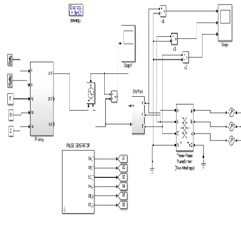
Fig 4: Simulation circuit
The fig 4, shows the three phase inverter circuit that includes Input voltage=24V, frequency=50HZ, Grid voltage=230V. The objective function in GA is written in such a way that it reduces 5th, 7th, 11th and 13th harmonics. From the fig 8 it is clearly shown that the proposed technique offers less harmonic content compared to standard method.
The selected harmonics such as (5th, 7th, 11th and 13th ) which are reduced completely for odd and even values of switching angles is shown in fig. 6 and fig. 7 respectively.
[image:3.612.330.530.515.697.2]International Journal of Emerging Technology and Advanced Engineering
Website: www.ijetae.com (ISSN 2250-2459, ISO 9001:2008 Certified Journal, Volume 4, Issue 2, February 2014)
108
[image:4.612.349.540.107.299.2]VI. RESULTS AND DISCUSSION
[image:4.612.58.280.118.692.2]Fig 5: Results for grid connected Pv by using optimized SHE PWM inverter
Fig 6: THD values for three phase inverter using even values of switching angles
Fig 7: THD values for three phase inverter using odd values of switching angles
Fig 8: comparison of THD values
[image:4.612.67.269.136.416.2]Three phase inverter with SPWM technique is simulated using matlab software. THD of this standard method is compared with proposed method and results are shown in fig 6. GA based SHEPWM technique with odd and even values shows reduced THD compared to SPWM technique.
Table I
Harmonic Content For Three Phase Inverters
Harmonics in output voltage
Odd values of switching
angle
(Harmonic content in %)
Even values of switching
angle
(Harmonic content in %)
5th 5.10 3.60
7th 2.24 0.74
11th 3.88 2.23
13th 1.98 1.08
The harmonics affect the performance of the power application. Due to 5th,11th,7th,13th harmonics attempt to drive the motor in reverse direction causing overheating, tripping of over current protection devices, skin effects, destructive heating leads to de -rating of machine occurs. The proposed method eliminates these particular harmonics by proper selection of odd and even values of switching angles.
VII. CONCLUSION
[image:4.612.334.555.388.552.2] [image:4.612.74.262.524.691.2]International Journal of Emerging Technology and Advanced Engineering
Website: www.ijetae.com (ISSN 2250-2459, ISO 9001:2008 Certified Journal, Volume 4, Issue 2, February 2014)
109
In the drive fields 5th and 11th harmonics create negative sequences and attempt to drive the motor in reverse direction causing overheating, tripping of over current protection devices. Odd numbers of switching angles are selected for eliminating 5th and 11th harmonics completely. The 7th harmonics causes destructive heating and leads to de-rating of machines like transformer and capacitor bank. Selection of even number of switching angles reduces the 7th harmonics completely. A simulated result has been presented for the THD for three phase inverter with odd and even values of switching angles is simulated and also compared with standard PWM method.
REFERENCES
[1] Javier Napoles, Jose I. Leon, Ramon Portillo, Leopoldo G. Franquelo, and Miguel A. Aguirre, ―Selective Harmonic Mitigation Technique for High-Power Converters,‖ IEEE Transactions on Industrial electronics, Vol. 57, No. 7, July 2010.
[2] V. G. Agelidis, A. Balouktsis, and C. Cossar, ―On attaining the multiple solutions of selective harmonic elimination PWM three-level waveforms through function minimization,‖ IEEE Trans. Ind. Electron.,Vol.55, No. 3, pp. 996–1004, Mar. 2008.
[3] Ali M. Eltamaly, ―A Modified Harmonics Reduction Technique for a Three-Phase Controlled Converter,‖ IEEE Transactions On Industrial Electronics, Vol. 55, No. 3, March 2008.
[4] V. Blasko, ―A novel method for selective harmonic elimination in powerbelectronic equipment,‖ IEEE Trans. Power Electron., Vol. 22, No. 1,pp. 223–228, Jan. 2007
[5] K. Sundareswaran, K. Jayant, and T. N. Shanavas, ―Inverter harmonic elimination through a colony of continuously exploring ants,‖ IEEE Trans.Ind. Electron., Vol. 54, No. 5, pp. 2558–2565, Oct. 2007.
[6] Jason R. Wells, Xin Geng, Patrick L. Chapman,Philip T. Krein, and Brett M. Nee, ―Modulation-Based Harmonic Elimination,‖ IEEE Transactions on Power Electronics,Vol. 22, No. 1, January 2007. [7] Vassilios G. Agelidis, AnastasiosBalouktsis, IoannisBalouktsis,
andCalumCossar ,―Multiple Sets of Solutions for Harmonic Elimination PWM Bipolar Waveforms: Analysis and Experimental Verification,‖ IEEE Transactions on Power Electronics, Vol. 21, No. 2, March 2006.
[8] K. L. Shi and H. Li, ―Optimized PWM strategy based on genetic algorithms, ‖IEEE Trans. Ind. Electron., vol. 52, no. 5, pp. 1458– 1461,Oct. 2005.
[9] Jason R. Wells, Brett M. Nee, Patrick L. Chapman, and Philip T. Krein, ―Selective Harmonic Control: A General Problem Formulation and Selected Solutions,‖ IEEE Transactions on Power Electronics, Vol. 20, No. 6, November 2005.
[10] John N. Chiasson, Leon M. Tolbert, Keith J. McKenzie, and Zhong Du, ―A Complete Solution to the Harmonic Elimination Problem,‖ IEEE Transactions on Power Electronics, Vol. 19, No. 2, March 2004.
AUTHOR’S PROFILE
D. Rajalakshmi received her bachelor’s degree from Shanmuga college of Engineering, Tanjore, Tamilnadu, India in Electrical and Electronics Engineering during 2000. She received her Master’s degree from Alagappa College of Engineering and Technology, Karaikudi, India during 2006.She has the teaching experience of more than 11 years. She is currently working as a Assistant Professor-Senior Grade at the department of Electrical and Electronics Engineering in Kumaraguru College of Technology, Coimbatore, India.


