iHONEYWELL
INTEROFFICE CORRESPONDENCE
PHOENIX OPERATIONS - HONEYWELL INFORMATION SYSTEMSDATE 771212
---
PHONE MAIL ZONE COPIESTO Specification File
---_ ---_ ---_ ---_ FR ... O ... M C.
Bjerke~
SF section: 14.4
COMPONENT LADC doc
n
0257A-Opage 1
SUBJECT I/O Design Specification
This specification has incorporated changes to the original design specification suggested by the I/O Design Review Committee and as such represents the design to be implemented.
SF section: doc II
date
14.4 0257A-O 771212 page
Design Specifications for a New I/O System 1. INTRODUCTION
The interim I/O System consists of two parts: IOQ and IDS. IOQ contains the caller and user interfaces; IDS, which was adapted from GCOS lOS, contains the I/O scheduling,
interrupt, and error recovery routines.
In order to meet several requirements of the CP-6 I/O
System, The interim IDS will be replaced with a new set of I/O processing routines ("the new IDS"). Although some
internal changes to IOQ will be necessary, the interfaces to IOQ for routines outside of the I/O System will remain
essentially unchanged. 1.1 REQUIREMENTS
The New I/O System for CP-6 will provide the following features:
o It will be written mostly in PL6 for easy maintenance. o Each handler will be an independent set of routines.
Common code will be primarily subroutines.
o Table searches will be minimized by using queue structures where applicable.
o It will be designed for a multi-processor environment. o It will be designed so that a wide variety of device
handlers may be accomodated, including those specifically mentioned herein.
r
o Disk I/O will be scheduled so as to mlnlmlze arm positioning delays and rotational latency.
1.2 Conventions
1.2.1 Module and Entry Point Names
All module and entry point names will have the following prefixes:
[image:2.612.57.546.74.702.2]1 .2.2
1.2.3
Prefix Module
Console Handler Disk Handler
Line Printer Handler IOQ
Card Punch Handler Packet Allocator Card Reader Handler
doc 11
date page
14.4 0251A-0 111212
3
NIC$ NID$ NIL$ NIO$ NIP$ NIQ$ NIR$ NIS$ NIT$ NIU$
Driver and Interrupt Distributor (BMAP) Magnetic Tape Handler
Utility Subroutines (PL6) External Symbol Names
All external symbol names defined in the above modules will have the prefix: NI_.
Calling Sequences
All calling sequences will be PL-6 calling sequences, which are described in AF sect. 6.3, #0137.
1 .3 Scope
This document describes the new IDS. Section 2 discusses those aspects of the hardware which must be taken into consideration when designing the 1/0 System. Section 3 contains an overview. Section 4 describes the data structures. Section 5 describes the procedures. Section 6 describes the changes to IOQ and entry points of IOQ which are used by lOS.
This document does not describe the individual device handlers, other than indicating the general modus operandi thereof.
1 .4 Re ferences
This design specification is based on information contained in the following documents:
58001190 43A239854 4 3A 177880 4 3A 171879 58001108 58008518 43A232230
EPS-1 4 Megaword System Controller
EPS-1 6000B Input/Output Multiplexer (10M) Centr, EPS-1 6000 10M Peripheral Subsystem Interface Ad EPS-1 MPC - PSI Link Adapter
EPS-l Unit Record MPC Controller/Subsystem EPS-1 MTP601 Tape Controller
2. HARDWARE CONSIDERATIONS
SF section: doc I
date page
14.4 0257A-O 771212
4
The general configuration of the L66 I/O hardware is shown in Fig. 2.1. There may be up to four CPUs. By the use of mask registers, I/O interrupts can be selectively directed to different CPUs. However, in order to maintain the current concept utilized in the Job Scheduler, all 1/0 interrupts will be sent to one CPU. There may be more than one System
Controller (SCU), but if all of the CPUs and IOMs are to have the same address space, the only purpose for more SCUs is to provide more than 4 megawords of memory. There may be up to four Input/Output Multiplexors (IOMs), but each 10M is
controlled independently and identically. Multiple IOMs can be used to provide greater I/O bandwidth and/or more I/O channels.
A ~icro-Programmed Controller (MPC) may have one or two Link
Adapters, each of which is capable of performing one data transfer operation at a time. Thus, two Link Adapters allow two simultaneous data transfer operations on dual-access tape and disk subsystems. Each Link Adapter may be connected to one or two Peripheral Subsystem Interface Adapters (PSIAs). The only purpose for having two PSIAs attached to one Link Adapter is to provide redundant paths to the MPC. Typically, the two PSIAs would be connected to different IOMs. Each PSIA may control up to eight I/O channels. The latter are usually called logical channels, to distinguish them from physical channels, which connect PSIAs to Link Adapters. The use of multiple logical channels on a PSIA depends on the type of
peripheral subsystem.
A unit record MPC can control up to eight peripherals such as card readers, line printers, and card punches. Each device is assigned the same logical channel number on all of the PSIAs connected to the MPC. Thus, there may be up to four paths to each device (2 Link Adapters X 2 PSIAs). However, since unit record data transfers are always buffered in the MPC and the data transfer time is much less than the device cycle time, more than one Link Adapt~r or PSIA only provide redundant paths to the MPC. Th us, a' un it record peri pher al wo uld usually be accessed by the same channel. Any contention between the devices for logical channels would be resolved by the MPC and thus would be transparent to the 1/0 software in the CPU.
A magnetic tape MPC can control up to 16 tape drives via a 1 X N or a 2 X N switch. Thus, with two Link Adapters, two tape drives may be doing simultaneous data transfers. Keeping a Link Adapter busy requires only two logical channels on the PSIA: one for the current request being processed, -and one to hold a request which can be started immediately when the
current request is finished. If there are more than two logical channels, a request issued to the lowest priority
channel may never be started because enough requests are issued on higher priority channels to keep the Link Adapter busy.
.
ISF section: doc ,
date page
14.4 0257A-O 771212
5
contention for the channels and, for maximum throughput, should keep both Link Adapters (if there are two) busy.
A disk subsystem may have one or two MPCs, each of which may have one or two Link Adapters, thus a maximum disk subsystem may perform four simultaneous data transfers.- On a disk
subsystem, the multiple logical channels of the PSIA are used to implement seek overlap. When a request is issued to a disk channel, the MPC initiates the seek phase of the request, then releases the logical channel so that other logical channels may be processed. In this manner, several disk drives may all be seeking simultaneously. When one of them arrives at the
requested sector, the MPC restarts the corresponding logical channel, and performs the data transfer operation. If a disk arrives at the requested sector while a data transfer is in progress, the on-sector interrupt from the drive will be
ignored and will occur again on the next revolution. However, if maximum performance is to be obtained from the disk
subsystem, the disk liD software must still schedule disk operations so as to minimize arm positioning delays and
3.
OVERVIEWdoc
n
date page0257A-O 771212
6
The new lOS will consist of the Driver, the Interrupt
Distributor, the Lost Interrupt Poller, and several device handlers, one for each type of supported devi~e. The Driver will set up the connect and payload channel mailboxes and issue the Connect
lID
Channel (CIOC) instruction to initiate theIIO
operation. The Interrupt Distributor will be entered whenever an interrupt occurs. It will determine the channel which
caused the interrupt and call the Poster of the device handler for that channel. The Lost Interrupt Poller is called
periodically to check for lost interrupts. In addition, there will be some common subroutines, such as an interface to KEYIN. Each handler will consist of a Scheduler and a Poster. The Scheduler is called by IOQ or the Poster to schedule the device
doc II
date page
14.4
0257A-O 111212
1
3.1 Table and Queue Structure
3. 1 • 1
3. 1 .2
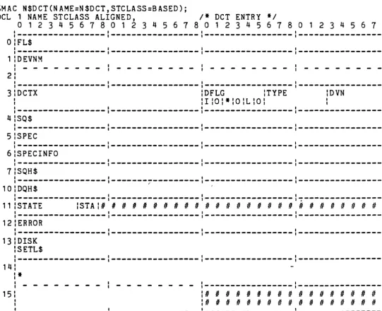
The static table structure for the New I/O System is shown in Fig. 3.1. The dynamic table and queue structure is shown in Fig. 3.2.
Tables
All of the I/O tables will be constructed at startup or
recovery time from configuration information stored on disk. Each table will have a pointer in the New I/O System's
static storage; this pointer will be set up when the table is constructed.
o Device Control Table (N$DCT)
The Device Control Table contains scheduling information for all local and remote devices. o Channel Table (NI$CHT)
The Channel Table points to the Driver Queue Header and Poster for each channel.
o Driver Queue Header (NI$DQH)
The Driver Queue Header contains scheduling data for a channel.
o Subsystem Queue Header (NI$SQH)
The Subsystem Queue Header contains scheduling data for a sub system.
Queues
All FIFO queues will be linked circularly, where each entry points to its successor, and the last entry points to the first. The queue header, i.e., the pointer to the queue, then pOints to the last entry in the queue. This saves space, in that the queue header needs only one pointer, yet allows easy enqueuing at either end of the queue and easy dequeuing at the head of the queue.
o Scheduler Queue
Each device has a queue of outstanding requests called the Scheduler Queue. For most devices, this will be a FIFO queue, but for disk, the requests will be ordered according to arm position, so as to minimize arm
doc #
date 0257A-O 771212
page
this device, the device Scheduler will move those requests which can be processed as a group to the Driver Queue.
o Assign Queue
Each subsystem will have a Assign Queue, which is a FIFO queue of devices waiting for channels to become available. The Assign Queue header is in the Subsystem Queue Header. The device Scheduler will put an idle device on the Assign Queue when there are requests on that device's Scheduler Queue. When a channel is
assigned to the device, the device will be removed from the Assign Queue.
o Driver Queue
Each channel will have a Driver Queue, which is a queue of requests that are ready to be started. This queue will be FIFO for most devices, but for disk, it will be ordered according to sector position within a track, so as to minimize rotational latency. At any moment in time, a Driver Queue will contain requests for only one device. For a disk channel, the Driver Queue will
contain requests for only a single cylinder of a disk pack. The device Scheduler enqueues requests on the Driver Queue when a channel has been assigned. The device Poster removes a request from the Driver Queue when it terminates.
This two-level queuing structure (Scheduler Queue and Driver Queue) is designed to maximize disk throughput. Basically, the Scheduler Queue is a queue of cylinders to be accessed, and the Driver Queue is a queue of requests for the current cylinder.
r
3.2
I/O Request Processingdoc , date page
0257A-O 771212
9
In the New I/O System, IOQ is called for both local and remote peripheral requests. On receiving a request, IOQ enqueues the request on the Scheduler Queue for the device. Then, if this request is for a remote device, IOQ calls the Front End
Interface to process the request. If this request is for a local device, IOQ allocates an lOS Request Packet and links it to the 10Q Request Packet. From the information in the IOQ Request Packet, IOQ then sets up the PCW, LPWX, and DCW list in the lOS Request Packet and calls the device Scheduler for the requested device.
If the device is idle, the device Scheduler enqueues the device on the Assign Queue for that subsystem. It then processes the Assign Queue, assigning a channel to each device thereon, until there are no more channels available or the Assign Queue is empty.
When a channel is assigned to a device (see section 3.4), the device is removed from the Assign Queue, and one or more
requests, depending on the device, are moved from the device's Scheduler Queue to the channel's Driver Queue. The Driver is then called to start the first request on the channel's Driver Queue.
The Driver sets up the connect and payload channel mailboxes and issues the CIOC instruction to start the I/O operation. When the interrupt occurs, the Interrupt Distributor determines
the channel number and calls the device Poster for that
channel. If no errors occurred, the Poster calls the Driver to start the next request on this channel. If there were no
errors or the errors were unrecoverable, the completed request is returned to IOQ for end-action processing. If the channel is now idle, the Poster calls the device Scheduler to restart the channel. If an error occurred that must be retried, the request is rescheduled tQ be processed next. If repositioning is required before the retry, reserved lOS Request Packets are used to effect the repositioning and are scheduled ahead of the request packet. This rescheduling may be done in either of two ways, depending on the device. For sequential deVices, i.e., devices other than disk, it requeues the lOS packet on t~
Driver Queue and calls the Driver to process the request. For disk devices, it requeues the IDS packet on the Scheduler Queue
and calls the device Scheduler to process the request. If an error occurred which requires operator intervention, a message is sent to the operator's console, and the request and the contents of the channel's Driver Queue are moved back to the beginning of the device'S Scheduler Queue. The device
Scheduler is then called to restart the channel (with requests for another device). The completion of the operator
doc , date page
14.4
0251A-D 711212
10
Distributor will post the special interrupt to the device
Poster. In the latter case, lOS' interface to KEYIN will post the key in to the Poster. When the operator intervention is complete, the device will be inserted at the beginning of the Assign Queue, and the device Scheduler will be called to
3.3
Channel AssignmentSF section: doc
n
date page
0257A-O 771212
1 1
The multiplicity of channels which may access a subsystem requires that channels be assigned dynamically to devices as they are needed. For unit record subsystems,. this channel assignment amounts only to selecting an available one from those configured. For tape and disk subsystems, Link Adapters and channels are assigned in a round-robin fashion. When there is a device to be assigned to a channel, the next Link Adapter with an available channel is found, and the device is assigned to the next available channel on that Link Adapter.
3.4
Direct Channel lIDAn entry point to the Driver will be provided for issuing a connect to a direct channel. The Front End Handler will have an Poster of its own for handling interrupts from the direct channel.
3.5
Lost InterruptsOccasionally, the hardware may fail in such a manner that no interrupts are returned from an lID operation. For this
reason, we need a Lost Interrupt Poller, i.e., a routine which is called periodically, say, every 5-10 seconds, to poll all of the active channels to see if a channel has been active for an unreasonably long time. If this is so, i.e., a lost interrupt has occurred, the device Poster is called with a unique
interrupt level. The latter will then take the appropriate error recovery action.
3.6
Error Statistics and Error LoggingAll lID errors will be logged in the system error log. Presumably there will b~ a ghost job that will monitor the error log and warn the operator if the error rate on a device exceeds an acceptable level (thresholding). The error log entry will include a time stamp, the external device
identification, the 10M and channel numbers, the hardware status words, and any extended status that may be available. In the case of a memory error during 110, memory mapping information will also be included.
3.7
Test and DiagnosticsSF section: doc II
date page
request. The lID System tables will have provision for reserving a device for T&D.
0257 A-O 771212
4. DATA STRUCTURES
SF section: doc ,
date page 14.4 0257A-O 771212 13
The following packets and tables will be used by the New 1/0
System:
4.1 10Q Request Packet (N$REQ)
The IOQ Request Packet is used for all 1/0 requests for both
local and remote devices. It contains the information which must be provided by the caller and space for information to be returned to the caller on completion.
~MAC N$REQ(NAME=N$REQ,STCLASS=BASED);
DCL 1 NAME STCLASS ALIGNED, If 1/0 REQUEST PACKET *1
o
123 4 5 6 7 801 2 3 4 5 678 0 1 2 3 4 5 6 7 801 234 5 6 7 ~1 1 ,
---~---I---I---~---I ---.
o
FL$1 1 ,
---,---,---,---_.
lOLA
DCTX lDRELADDR
1 , 1
-,-I~, ---2 BUFSIZE
I 1
I I
:OPFLG
lU:A\E:ElWIB\HIRI:
1 , 1
---,---,---1---3
BUF$1 1 ,
---,---,---,---4 PTP
:n
#n
#n , n ,
# # # # # # # # #, 1 1
---,---,---1---5 DCB$
1 1 ,
---,---1---,---6 EAENTRY
1 I ,
---.---_.,---,---7 EAINFO
1 , I
---,---1---,---10 EVNTINFO
1 , ,
---,---,---,---11 ARSIZE ;*;CC ;USERII
: IERR :ABN : : ;I;PlI:EIE:B:
1 , 1
---1---1---,---12 ARCT
1 , I
---,---,---, ---~
13 RCT
, , 1
---,---,---, ---~---~
2 FL$ PTR, 2 DLA ALIGNED,
3
DCTX UBIN(15) UNAL,3
DRELADDR UBIN(21) UNAL, 2 SLA REDEF DLA,3
SETX UBIN(9) UNAL,3
SRELADDR UBIN(27) UNAL,1* LINK TO NEXT PACKET IN QUEUE *1
II
DEVICE LOGICAL ADDRESS *1II
DEVICE TABLE INDEX *1II
DEVICE-RELATIVE ADDRESS *1II
SET LOGICAL ADDRESSII
1* PACK SET INDEX *1
2 BUFSIZE UBIN(20) UNAL, 2
*
BIT ( 1 ) ,2 FC UBIN(6) UNAL, 2 OPFLG,
3 US ER BIT (1 ) ,
3 ARS BIT(1), 3 E VN T BIT ( 1 ) , 3 EA BIT(1), 3 W A IT BIT (1 ) ,
3
BPF BIT(1), 3 HOLD BIT (1 ) , 3 REQ BIT (1 ) , 3 SET BIT (1 ) , 2 BUF $ PTR,2 BUFADDR REDEF BUF$ UBIN(26), 2 BUFVIRT REDEF BUF$,
3
*
BIT(5),3 BASE UBIN(18) UNAL, 3 BYTE UBIN(3) UNAL, 3
*
BIT(10),2 BUFREAL REDEF BUF$, 3 EXTA UBIN(6) UNAL, 3 ADR UBIN(18) UNAL, 3 BYTE UBIN(2) UNAL, 3
*
BIT(10),2 PTP UBIN(18) UNAL, 2 DCB$ PTR,
2 EAENTRY EPTR, 2 EAINFO UBIN(36),
IMENDj
2 EVNTINFO UBIN(36), 2 ARSIZE UBIN(20) UNAL,
2
*
BIT (1 ) ,2 CC, 3 ERR,
4 10 BIT (1 ) , 4 PE BIT(1), 4 I NVD BIT (1 ) , 3 ABN,
4 E OF BIT ( 1 ) , 4 EOT BIT(1), 4 BOT BIT ( 1 ) , 2 USER# UBIN(9) UNAL, 2 ARCT SBIN ~ORD,
2 RCT SBIN WORD;
SF section: doc f1
date page
0251A-O 111212
14
1* BUFFER SIZE (BYTES) *1
1* LOGICAL FUNCTION CODE *1 1* OPERATION FLAGS *1
1* USER-ASSOCIATED lID *1 1* SET ARS OF DCB *1
1* REPORT COMPLETION EVENT *1 1* CALL END-ACTION ROUTINE *1
1* BLOCK ASSOCIATED USER AFTER QUEUE 1* BUF$ CONTAINS PTR -> BUFFER *1
1* DO NOT RELEASE PACKET ON COMPLETI 1* RE-QUEUE PACKET *1
1* O=REQ TO DEV, 1=REQ TO SET *1 1*
->
BUFFER IF BPF='1 'B *11* BUFFER ADDRESS IF BPF='O'B *1 1* VIRTUAL BUFFER ADDRESS IF PTP
1* REAL BUFFER ADDRESS IF PTP=O *1
1* BPF=O: PAGE TABLE POINTER (O=REA) 1*
->
USER'S DCB *11* END-ACTION PROCEDURE *1 1* END-ACTION PARAMETER *1 1* EVENT INFO *1
1* ACTUAL RECORD SIZE *1
1* LOGICAL COMPLETION CODE (O=OK)
*
1* 1/0 ERROR *1 1* PARITY ERROR *1
1* INVALID OPERATION */
/* END-OF-FILE */
1* END-OF-TAPE *1
1* BEGINNING-OF-TAPE */
1* USER ID *1
/* ACTUAL RECORD COUNT *1
4.2 105 Request Packet (NI$REQ)
SF section: doc II
date page 14.4 0257A-O 771212 15
The 105 Request Packet is allocated by IOQ for a local device I/O request. It resides in real memory and contains
information specific to a local device I/O operation.
~MAC NI$REQ(NAME=NI$REQ,STCLASS=BASED);
DCL 1 NAME STCLASS DALIGNED, /* I/O REQUEST PACKET */
o
1 2 3 4 5 6 7 8 0 1 234 567 8 0 1 234 567 8 0 1 234 567 8I , , I
I---,---~---I---~--
,---O;FL$
I , I I
,---,---,---,---1 lIOQ$
I , I I
,---,---,---,---2'DCT$
, , I
---,---,---,---3 ERReT lLPWCONT In
n n n
# # #n
#n
H
# # # # # # # # # # # #n
I I I
---,---,---,---4
pcw
*
lAEXCHANNEL lPTP lFLAGS
I I I
---,---,---,---_.
6 LPWX
BASE :SIZE
I I I
---1---1---,---7
Dew
FWA lICP lTYPE lTALLY
I I I
---,---,---,---_.
10 Dew
FWA :ICP lTYPE lTALLY
I I I
---,---,---,---11 Dew
FWA lICP lTYPE lTALLY
I I I
---,---,---,---.
12 DCW
FWA lICP lTYPE lTALLY
, I I
---,---,---,---_.
13
Dew
FWA
,
1
lICP lTYPE ITALLY,
---,---,---1---14 SEEK
seL :SSZ lSECTOR
---:---:---: ---~ 15 CL$
I , - ,
~I-I-,
---16 STATUS
P:P;MAJOR lMINOR :O;M;* :I;*:CHAN :IOM l* :RCR
, I I
---.---,---,---17
lNCP :R;* lTALLYR
I , I
2 FL$ PTR, 2 IOQ$ PTR, 2 DCT$ PTR,
2 ERRCT UBIN(6) UNAL, 2 LPWCONT BIT(6), 2 PCW DALIGNED,
3 I B1T(12),
3 AEX UBIN(6) UNAL, 3 I DC W BIT ( 3) ,
3 M BIT(1), 3
*
B1T(14),3 CHANNEL UBIN(9) UNAL, 3 PTP UBIN(18) UNAL, 3 FLAGS BIT(9),
2 LPWX ALIGNED,
3 BASE UBIN(18) UNAL, 3 SIZE UBIN(18) UNAL,
2 DCW(O:4),
3 FWA UBIN(18) UNAL, 3 ICP UBIN(3) UNAL, 3 TYPE BIT(3),
3 TALLY UBIN(12) UNAL,
JMEND;
2 SEEK ALIGNED,
3 SCL UBIN(12) UNAL, 3 SSZ UBIN(4) UNAL, 3 SECTOR UBIN(20) UNAL, 2 CL$ PTR,
2 STATUS DALIGNED, 3 PRESENCE BIT(1), 3 POWEROFF BIT(1), 3 MAJOR BIT(4), 3 MINOR BIT(6), 3 ODD BIT(1), 3 M ARKE R BIT ( 1 ) ,
3 I BIT(2), 3 I NINT BIT (1 ) , 3 I BIT(1), 3 CHAN BIT(3), 310M BIT(3), 3 I 8IT(6),
3 RCR UBIN(6) UNAL, 3 NWA UBIN(18) UNAL,
3 NCP UBIN(3) UNAL, 3 READFLG BIT(1),
3 I BIT (2) ,
3 TALLYR UBIN(12) UNAL;
SF section: doc II
date page 14.4 0257A-O 771212 16
II
LINK TO NEXT PACKET IN QUEUEII
II
->
ASSOCIATED IOQ REQUEST PACKETII
->
DEVICEII
II
ERROR RETRY COUNTII
II
LPW CONTROL BITSII
1* PERIPHERAL CONTROL WORD *1
II
ADDRESS EXTENSION (FOR REALlID)
II
INIT( '7 '0), rDCW FLAGII
II
MASK BITII
II
CHANNEL NUMBERII
II
PAGE TABLE POINTERII
II
PTP, PGE, AUXII
II
LIST POINTER WORD EXTENSIONII
II
LOWER BOUND (MOD 2 WORDS)II
II
SIZE (WORDS)II
1* DCW LIST
II
1* FIRST WORD ADDRESS
II
II
INITIAL CHARACTER POSITION *1 1* DCW TYPEII
II
WORD COUNTII
II
DISK SEEK ADDRESS WORDII
II
SECTOR COUNT LIMIT *1II
SECTOR SIZEII
II
SEEK ADDRESSII
II
LINK TO DCW LIST PACKETSII
II
STATUS WORDSII
II
ALWAYS ONEII
II
POWER OFF STATUS flII
DEVICE MAJOR STATUSII
II
DEVICE MINOR STATUSII
II
ODD WORD COUNTII
II
MARKER INTERRUPTII
If
INITIATION INTERRUPTII
II
CHANNEL STATUSII
If
10M STATUSII
If
RECORD COUNT RESIDUE*1
If
NEXT WORD ADDRESSII
If
NEXT CHAR POSITIONII
If
READIWRITE FLAGII
SF section: doc II
date page 14.4 0257A-O 771212 17
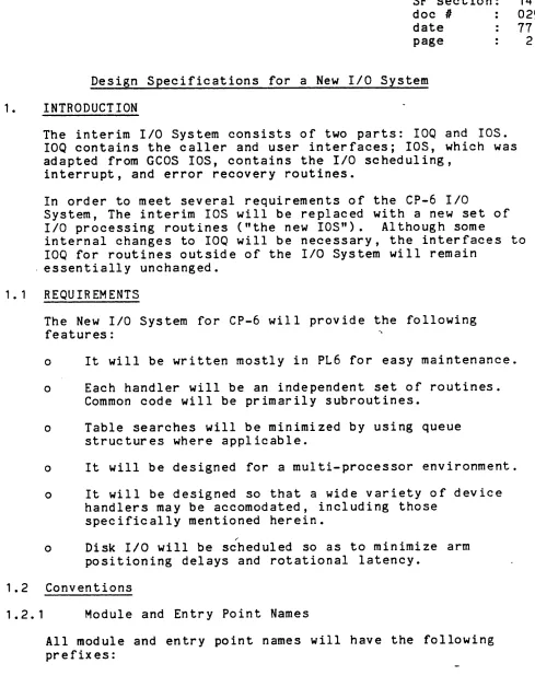
4.3 Device Control Table (N$DCT)
The Device Control Table contains scheduling information for both local and remote devices. It is accessed by a parallel table of pointers, called N$DCT$; the index into this table of pointers is the Device Control Table Index (DtTX). The pointer table will be pointed to by the pointer, N$DCT$$. Thus, a
reference to a field in the Device Control Table would appear as:
N$DCT$$->N$DCT$(DCTX)->N$DCT.field.
This pointer-table structure allows OCT entries to be of different sizes and allows dynamic allocation of packets for remote devices.
~MAC N$DCT(NAME=N$DCT,STCLASS=BASED);
DCL 1 NAME STCLASS ALIGNED, 1* OCT ENTRY *1
o
1 234 5 6 1 801 234 567 801 234 567 801 234 5 6 7 EI t I I
,---,---1---.---O:FL$
t t t ,
I---,-~---I---
,---1 :DEVNM
, I , ,
, - - - , - - - I - - - , - - - -2'
I , ,
---,---,---,---3 DCTX :DFLG ITYPE :DVN
:I:O:*;O:L:O:
I , I
---,---,---,---4 SQ$
, I I
---~---,---I---I ---. 5 SPEC
, , I
---I---~~---I---I ---.
6 SPECINFO
,
,
,
---,---,---,---.
1 SQH$
, , I
-I---~---I-~---I
---10,DQH$
,
,
,
,
I---I---I-~---I~---11 :STATE :STA:n
Inn n
#n n
#n n n n
# # # #n n
# #n n
#n n n
I , , ,
,---1---,---,---12 ERROR
,
,
,
---,---,---,---13 DISK
SETL$
,
,
,
---I---I-~---,---~---14
*
,
,
,---,---15
:n n n n n n n
# # #n
#n n n
#n
1
:n n n n
# #n
# # #n
# #n
# # #, I , ,
[image:17.615.57.598.312.751.2],---,---,---,---~MEND;
2 FL$ PTR,
2 DEVNM CHAR(8) ALIGNED, 2 DCTX UBIN(18) UNAL,
2 DFLG,
3 INPUT BIT(1), 3 OUTPUT BIT (1 ), 3
*
BIT (1 ) ,3 OCK BIT (1 ) , 3 LCL BIT(l), 3 OLDSC BIT (1 ) , 2 TYPE UBIN(6) UNAL, 2 DVN UBIN(6) UNAL, 2 SQ$ PTR,
2 SPEC EPTR,
2 SPECINFO UBIN(36), 2 SQH$ PTR,
2 DQH$ PTR,
2 STATE UBIN(6) UNAL,
2 STATUS UBIN(2) UNAL,
2 ERROR UBIN(36),
2 DISK,
3
SETL$ PTR, 3*
BIT(54),2 PRINTER REDEF DISK,
3 VFC$ PTR, 3 CHAIN$ PTR,
3 VFCL UBIN(9) UNAL, 3 CHAINL UBIN(9) UNAL;
SF section: doc II
date page
14.4 0251A-O 171212
18
/* FORWARD LINK FOR ASSIGN QUEUE */ /* DEVICE NAME E.G. LP02 */
/* DCT INDEX *1
/* DEVIC E FLAGS
*
I/* OPERATOR'S CONSOLE */ /* LOCAL DEVICE *1
/* DEVICE TYPE */ /* DEVICE NUMBER */
/* HEAD OF SCHEDULER QUEUE */ /* SPECIAL INTRP ENTRY *1
/* SPECIAL INTRP INFORMATION */ /* -> SUBSYSTEM QUEUE HEADER */ /* CURRENTLY ASSIGNED DRIVER QUEUE /* SCHEDULING STATE */
/* DEVICE STATUS (UP,DOWN,T&D) *1
/* ERROR STATISTICS */ /* DISK-SPECIFIC DATA *1
1* LINK TO NEXT PACK IN SET *1
/* PRINTER-SPECIFIC DATA */
1*
->
VFC IMAGE */1*
->
CHAIN IMAGE *1 1* VFC-- IMAGE LENGTH* /
4.4 Device Table (NI$DVT)
SF section: doc II
date page
14.4 0257A-O 771212 19
The Device Table contains static information for each type of local device in the system. The index into this table is the device type, which is contained in each local. entry of the Device Control Table. This table will be pointed to by the pointer, NI$DVT$.
~MAC NI$DVT(NAME:NI$OVT,STCLASS:"(O:O) BASED(NI$DVT$)t1);
DCL 1 NAME STCLASS ALIGNED,
o
1 234 5 6 7 801 234 5 6 1 8 0 1 2 3 4 5 6 1 8 0 1 2 3 4 561 EI I I
---1---1---,---o
DOT$I I I
---1---1---1---1 S CHED
1
I
I
---,---,---1---.
2 POST
I I I
---,---,---,---_.
3
CYLINDERS lSURFACES : CYLSIZ E :SECTORS lP HII 1 I
---1---,---,---.
4 MODEL
5
I I I
- - - 1 - - - 1 - - - 1 - - -
-I I I
---~--,-,-I
---2 OOT$ PTR, 2 SCHED EPTR, 2 POST EPTR,
2 CYLINDERS UBIN(12) UNAL, 2 SURFACES UBIN(6) UNAL, 2 CYLSIZE UBIN(9) UNAL, 2 SECTORS UBIN(6) UNAL, 2 PSIA BIT(l),
1* PRE-HANDLER ENTRY *1 1*
->
DEVICE SCHEDULER *1 1* POST-HANDLER ENTRY *11* (DISK) NUMBER OF CYLINDERS *1 1* (DISK) NUMBER OF SURFACES *1 1* (DISK) NUMBER OF SECTORS/CYLINDE 1* (DISK) NUMBER OF SECTORS/TRACK
*
1* DEVICE ATTACHED TO PSIA *1 2 MODEL CHAR(8) ALIGNED;
~MEND;
4.5 Channel Table (NI$CHT)
SF section: doc #
date page
14.4
0257A-O 771212 20
The Channel Table is indexed by the 10M number and the channel number and contains an entry for each possible channel
(overhead and payload) in the system. The entry for each configured channel contains a pointer to the Driver Queue Header and an entry pointer to the Poster for that channel. This table will be pointed to by the pointer, NI$CHT$.
~MAC NI$CHT(NAME=NI$CHT,STCLASS="(0:63) BASED(NI$CHT$)"); DCL 1 NAME STCLASS ALIGNED,
o
123 4 567 801 2 3 4 5 6 7 801 2 3 4 5 6 7 801 2 3 4 5 678,
,
,
,
,---,---,---,---O:DQH$
,
,
,
,
1---,---1---1---1 :POSTER
,
,
,
,
,---1---,---1---2 DQH$ PTR, 2 POSTER EPTR;
~MEND;
4.6 Driver Queue Header (NI$DQH)
SF section: doc II
date page
14.4 0257A-O 771212 21
The Driver Queue Header contains configuration and scheduling information for a particular channel. For multi-device
subsystems, the Driver Queue Headers are grou.ped by Link
Adapter; for unit record subsystems, the Driver Queue Headers are grouped by device.
~MAC NI$DQH(NAME=NI$DQH,STCLASS=BASED)j DCL 1 NAME STCLASS ALIGNED,
o ,
234 567 8a ,
234 567 8a
1 234 567 801 234 567 ~I I I I
,---1---1---,---O:FL$
, I I I
1---,---,---,---.
"GATE
I I I
---,---.---,---_.
:STATUS :LA :STATE :LOSTINT 2 IOCHAN
10M :CHANNEL :
I I I
---,---,---,---3 SQH$
I I ,
---,---,---,
---~---4 DQ$
I , ,
---,---,---,---5 ERROR
I I I
---,---,---,---2 FL$ PTR,
2 GATE SBIN ALIGNED, 2 IOCHAN,
310M UBIN(6) UNAL, 3 CHANNEL UBIN(6) UNAL, 2 STATUS UBIN(6) UNAL, 2 LA UBIN(6) UNAL, 2 STATE UBIN(6) UNAL, 2 LOSTINT UBIN(6) UNAL, 2 SQH$ PTR,
2 DQ$ PTR,
2 ERROR UBIN(36); ~MEND;
/* LINK TO NEXT CHANNEL ON LINK ADA /* GATE ON DRIVER QUEUE */
/* 10M NUMBER */ /* CHANNEL NUMBER */
/* CHANNEL STATUS (UP,DOWN,T&D) */ /* LINK ADAPTER NUMBER */
/* SCHEDULING STATE */ /* LOST INTERRUPT FLAG */
/*
->
SUBSYSTEM QUEUE HEADER */ /* HEAD OF DRIVER QUEUE */SF section: doc
n
date page 14.4 0257A-O 771212 22
4.7 Subsystem Queue Header (NI$SQH)
For each configured peripheral subsystem, there is a Subsystem Queue Header. It contains conffguration and scheduling
information for that subsystem. Each Subsystem Table entry consists of two sections: the first is global data, and the second is a table of data for each Link Adapter on the
subsystem.
%MAC NI$SQH(NAME=NI$SQH,STCLASS=BASED); DCL 1 NAME STCLASS ALIGNED,
o
1 2 3 4 567 8 0 1 2 345 6 7 8 0 1 2 3 4 567 8 0 1 2 3 456 1 Et t l t
,---,---,---,---O'GATE
I , ,
---,---,---,---1 DCT$
I I ,
---,---,---,---2 NDCT INLA ILAX
:n
# #n n n
# #n
#n
# # # # # # # # # # # # 7I , ,
---,---1---,---3 AQ$
I I ,
---,---,---1 ---~---.
4 LA
NCHAN INACT :STAln #
n
# #n n
# #n n n
#n
# # #n n
# # ;5
6
, I ,
---1---,---,---DQH$
, I I
---,---,---,---_.
ERROR
,
,
,
---,---,---1---LEVEL 2 ARRAY: 4 (' 4'0) ENTRIES TOTAL.
,
,
,
,
,---,---,---,---2 GATE SBIN ALIGNED, 2 DCT$ PTR,
2 NDCT UBIN(6) UNAL, 2 NLA UBIN(3) UNAL, 2 LAX UBIN(3) UNAL,
2 AQ$ PTR,
2 LA(O:3),
3 NCHAN UBIN(6) UNAL, 3 NACT UBIN(6) UNAL, 3 STATUS UBIN(2) UNAL,
3 DQH$ PTR,
3 ERROR UBIN(36);
1* GATE ON SCHEDULING TABLES *1 1*
->
FIRST DCT ENTRY *11* NUMBER OF DEVICES *1
1* NUMBER OF LINK ADAPTERS *1 1* NEXT LINK ADAPTER INDEX *1 1* HEAD OF ASSIGN QUEUE *1 1* LINK ADAPTER TABLE: *1
1* NUMBER OF CONFIGURED CHANNELS *1 1* NUMBER OF ACTIVE CHANNELS *1 1* LINK ADAPTER STATUS (UP,DOWN,T&D 1*
->
NEXT CHANNEL'S DRIVER QUEUE H4.8 10M Table
SF section: doc II
date page
14.4 0257A-O 771212 23
The 10M table contains data needed to manage the overhead channels of an 10M. There is a table of pointers to the 10M table packets; this pointer table is indexed by the 10M number.
~MAC NI$IOM(NAME=NI$IOM,STCLASS=BASED); DCL 1 NAME STCLASS ALIGNED,
o
123 4 5 6 7 801 2 3 4 5 6 7 801 2 3 4 567 801 234 567 8I I I
---,---,---,---o
GATEI I I
---,---,---,---, MBX$
I I I
---,---,---1---2 I OM II :LASTCON :NEXTF : N EXTS :MAXS
:*
: ADDREt I I
---,---1---1---3 FLTBUF :SPECBUF
• I I
---,---,---,---~MEND;
2 GATE SBIN ALIGNED,
2 MBX$ PTR,
2 IOMO UBIN(6) UNAL, 2 LASTCON UBIN(6) UNAL, 2 NEXTF UBIN(6) UNAL, 2 NEXTS UBIN(6) UNAL, 2 MAXS UBIN(6) UNAL,
2
*
BIT(3),2 ADDRESS UBIN(3) UNAL, 2 FLTBUF UBIN(18) UNAL, 2 SPECBUF UBIN(18) UNAL;
1* GATE ON CONNECT CHANNEL *1 1*
->
MAILBOXES *11* 10M NUMBER *1
1* LAST CONNECTED CHANNEL *1
1* INDEX TO NEXT WORD IN FAULT BUFFI 1* INDEX TO NEXT WORD IN SPECIAL IN~
1* WORST CASE NEXTS *1
1* 10M ADDRESS (FOR CIOC) *1
5. PROCEDURES
5.1 Driver (NIS$DRIVER)
SF section: doc ,
date page
14.4 0257A-O 771212 24
The Driver starts the 1/0 operation for the first request on a given Driver Queue.
Calling Seguence
CALL NIS$DRIVER(DQH$);
where: DQH$ points to a Driver Queue Header. Entry Conditions
Interrupts must be disabled.
The Driver Queue must not be locked. The channel must not be busy.
Exit Conditions
The 1/0 is started. ~
The Driver Queue is not locked. Description
The
pew
(Peripheral Control Word) is set up from the PCW and PTP fields of the request packet and the channel number of the Driver Queue Header. The payload channel mailbox is set up to point to the DCW list and status doubleword of the request packet. The CIOC is then issued with the connect channel5.2 Interrupt Distributor (NIS$INTDIS)
SF section: doc
n
date page
14.4 0257A-O 771212 25
The Interrupt Distributor determines the interrupting channel and calls the associated Poster.
Calling Seguence
The Interrupt Distributor is called by the wired-in CLIMB instruction to the entry descriptor at location 30(octal). This entry descriptor must be type 11 and must specify the
Monitor's Linkage Segment, the Monitor's privileged Instruction Segment, and WSR (Working Space Register) number O.
Description
The Interrupt Distributor determines the interrupt level and the interrupting channel number from the Interrupt Cell number in the Safe-Store Frame and the corresponding IMW (Interrupt Mask Word). If the interrupt was from the system fault channel or the special status channel, the fault word or special status word, respectively, is examined to determine the associated payload channel number. The fault word or special status word is altered to look like a peripheral status word by inserting a major status code of 17(octal) for a fault interrupt or
16(octal) for a special interrupt. The fault word or special status word is passed to the device Poster along with the
Driver Queue Header of the interrupting payload channel and the interrupt level. The device Poster for the payload channel is then called to process the interrupt. On return from the
device Poster, the Interrupt Distributor loops back to process any other interrupts that were indicated in the current IMW. When all of them have been processed, the Interrupt Distributor
. 5.3
Lost Interrupt Poller (NIS$LOSTINT)SF section: doc
n
date page
14.4
0257A-O 771212
26
The Lost Interrupt Poller is called periodically to check for lost interrupts.
Calling Sequence
CALL NIS$LOSTINT; Entry Conditions
Interrupts must be enabled. No driver queues may be locked. Exit Conditions
Interrupts will be enabled.
No driver queues will be locked. Description
The Lost Interrupt Poller is called periodically, say, every 5-10 seconds. Each time it is called, it scans all of the channels' Driver Queue Headers. For each channel, if the Lost Interrupt Flag is not set and the channel is active, the Lost Interrupt Flag is set. If the Lost Interrupt Flag is already set, a lost interrupt condition has occurred, since the channel has been active since the previous polling cycle. (The Lost
5.4 Lock Gate Routine (NIS$LOCK)
doc /I
date page
0257A-O 771212 27
The Lock Gate routine is a fast assembly-language routine for locking a gate.
Calling Sequence
CALL NIS$LOCK(GATE);
where: GATE is the gate to be locked. Entry Conditions
GATE must be a word-aligned 36-bit field. Exit Conditions
The gate is locked. De s c rip t ion
A gate is used to synchronize code sequences r~nning in two or more CPUs. The gate is locked when its value is zero. When a gate has been locked by one CPU, it cannot be locked by any other CPU. This routine locks a gate by using a Load
Accumulator and Clear (LDAC) instruction. If the gate is already locked, NIS$LOCK loops on the LDAC until it is
5.5 Queue Handling Macros
doc , date page
These PL-6 macros are provided for enqueuing and dequeuing packets from FIFO queues.
Calling Seguences
To enqueue a packet at the tail of a queue:
~ENQUEUE(pn=p$,Qn=Q$);
To enqueue a packet at the head of a queue:
~REQUEUE(pn=p$,Qn=Q$);
To dequeue a packet from the head of a queue:
~DEQUEUE(pn=p$,Qn=Q$);
where:
P$ points to the packet to be queued, or, on return, points to the packet dequeued.
Q$ points to the queue header. Entry Conditions
None
Exit Conditions ENQUEUE
REQUEUE
The specified packet has been linked into the queue. DEQUEUE
0257A-O 771212
28
The first packet on the specified queue has been removed from the queue and returned in Pt. If the queue is empty, P$=ADDR(NIL) is returned.
Description
If the queue is empty, ENQUEUE and REQUEUE set the queue header to point to the new packet, and set the link field of the
packet to point to itself. If the queue is not empt3, ENQUEUE inserts the new packet after the packet pOinted to by the queue header, then sets the queue header to point to the new packet. REQUEUE inserts the new packet after the packet pointed to by the queue header but does not change the queue header.
SF section: doc II
date page
0257A-O 771212
29
5.6 Device Scheduler (Nlx$SCHEO)
SF section: doc ,
date page
0257A-O
771212
30
The device Scheduler enqueues the device on the Assign Queue, assigns a channel to the device, and schedules a list of requests to be executed.
Calling Sequence
CALL Nlx$SCHED(DCT$); where:
DCT$ points to the Device Control Entry for the device. Entry Conditions
Interrupts are enabled.
The Subsystem Tables and Driver Queue are not locked. Exit Conditions
If a channel was available, lID has been started. Interrupts are enabled.
The Subsystem Tables and Driver Queue are not locked. Description
On entry to the device Scheduler, if there are requests on the device's Scheduler Queue and the device is not busy, it is enqueued on the Assign Queue. Then, if there is an available channel, the first device on the Assign Queue is removed and assigned to the next availaole channel, and requests from the device's Scheduler Queue are moved to the channel's Driver Queue. For most devices, only one list of requests will be moved to the Driver Queue at a time. However, in order to minimize disk rotational latency, all of the disk requests for a cylinder will be moved to the Driver Queue as a group. The Driver is then called to start the first request. On return
5.1 Device Poster (Nlx$POSTER)
SF section: doc ,
date page
The device Poster analyzes interrupts, calls the Driver to restart the channel, performs error recovery, and returns completed requests to IOQ for end-action processing.
Calling Sequence
CALL NIx$POSTER(DQH$,LEVEL,STATUS);
0251A-O 711212
31
where:
DQH$ points to the Driver Queue Header of the interrupting payload channel.
LEVEL is the interrupt level:
o
12
3
overhead termination marker
special
STATUS is the fault word or special status word. Entry Conditions
Interrupts are disabled.
The Driver Queue is not locked. Exit Conditions
Interrupts are disabled.
The Driver Queue is not locked. Description
t
The device Poster is called by the Interrupt Distributor to process the interrupt. If this is a termination interrupt, the current request is removed from the Driver Queue. If there were no errors, the Driv~r is called to start the next request on the Driver Queue. Marker interrupts are ignored; this
interrupt level is included for the Front End (Direct Channel) Handler. If this is a special interrupt, i.e., an asynchronous
interrupt, it may be used by error recovery routines; otherwise it will be passed to IOQ for a possible caller of special
interrupt control. If this is a fault interrupt, the fault word is stored in the second status word of the current
request.
If there were no errors or the errors were unrecoverable, the completed request is returned to IOQ for end-action processing. If a recoverable error occurred, the appropriate error recovery technique is applied. To retry the operation, the device
6. IOQ INTERFACES FOR lOS
SF section: doc
n
date page
The following entry points to IOQ are used only by lOS.
6.1 I/O Completion Routine (NIO$COMP)
14.4 0257A-O 771212
32
NIO$COMP performs all caller- and user-related actions related to I/O completion.
Calling Sequence
CALL NIO$COMP(Q$);
where: Q$ points to the request. Entry Conditions
Interrupts are enabled. No gates are locked. Exit Conditions
The request packet has been either returned to the caller, requeued for a new operation, or released.
Description
From the hardware status words, NIO$COMP sets the completion code, actual record size, and actual record count fields of the 10Q Request Packet and releases the lOS Request Packet. Then, depending on the setting of bits in the request's OPFLG field, NIO$COMP may do one or more of the following:
o Set completion information in the user's DCB.
o Report an "I/O Completion" event to the Job Scheduler. o Call an end-action ~outine. (Note: an end-action routine
doc , date
page
6.2 Special Interrupt Completion Routine (NIO$SPCOMP)
0257A-O 771212
33
If a caller has requested special interrupt control, NIO$SPCOMP calls his end-action routine.
Calling Seguence
CALL NIO$SPCOMP(DCTX,STATUS); where:
DCTX is the Device Table Index of the interrupting device. STATUS is the special interrupt hardware status word.
Entry Conditions
Interrupts are enabled. No gates are locked. Exit Conditions
If this special enterrupt has been requested, the caller's end-action routine has been called.
Description
'.
N#VT
I
'
U----I
-
I ... -;.. ,'-I 7~ :.:..
uQH#
/
SQH$
-f)QHi
..
-;~
.
-.
/ /
IriS:? ,~5
QH-# -"-
-~.-
'-I
~'-' -:~
.--DQJiJt
/
,/
!
-~---~---
....
5 CN r=.DUL(;~
Q
(.IE l.I ENji<EQ.
AQ# ---;--- FLf$
LA
DQH$ .
---'- F L ,
t--'-":'---~