© 2018, IRJET | Impact Factor value: 6.171 | ISO 9001:2008 Certified Journal | Page 2850
Experimental Study on Flexural and Compressive behavior of Cold
Formed Steel Back To Back Supacee Section
Ganeshkumar R
1,
Suresh Babu S
2, Dr.Leema Rose A
31
PG Student, Dept. of Civil Engineering, Valliammai Engineering College, Chennai, Tamil Nadu
2Assistant Professor, Dept. of Civil Engineering,Valliammai Engineering College, Chennai, Tamil Nadu
3Associate Professor, Dept. of Civil Engineering,Valliammai Engineering College, Chennai , Tamil Nadu
---***---Abstract
- Cold formed steel sections or light gauge steel sections are thin walled sections which are gaining popularity in recent years. These sections are cold-formed from carbon or low alloy steel sheet, strip, plate, or flat bar in cold-rolling machines or by press considered and worked on as a replacement hot rolled section. Unusual sectional configurations can be produced economically by cold forming operations, and consequently favourable strength‐to‐weight ratios can be obtained. Supacee section is the special case c section. This section is equipped with both intermediate and edge stiffeners. This section is tested of its flexural and compressive behaviour (i.e., as both beam and column). In this present study the failure pattern and region of failure are to be analyzed.Key Words: Cold Formed Steel, Supacee section, Flexural member, Compression member, Intermediate stiffener, Edge stiffener, Numerical analysis, Experimental analysis.
1. INTRODUCTION
Cold-formed steel (CFS) is the common term for products made by
rolling
orpressing
steel into semi-finished or finished goods at relatively low temperatures (cold
working
). Cold-formed steel goods are created by the working of steel billet, bar, or sheet usingstamping
, rolling (includingroll forming
), or presses to deform it into a usable product. Cold-worked steel products, such as cold-rolled steel (CRS)bar stock
and sheet, are commonly used in all areas of manufacturing of durable goods, such as appliances or automobiles, but the phrase cold-formed steel is most prevalently used to describe construction materials. In building construction, cold-formed steel products can be classified into three categories: members, panels, and prefabricated assemblies. Typical cold-formed steel members such as studs, track, purlins, girts and angles are mainly used for carrying loads while panels and decks constitute useful surfaces such as floors, roofs and walls, in addition to resisting in-plane and out-of-plane surface loads. Prefabricated cold-formed steel assemblies include roof trusses, panelized walls or floors, and other prefabricated structural assemblies. Supacee section has a strengthened cross section than traditional c section. It is equipped with four intermediate stiffeners in web region (V-shaped) and distinctive edge stiffener with a return lip, where the lip portion is bent additionally than conventional 90 degree bending from flanges towards the section. This section is toanalytically (ABAQUS software) and experimentally studied. The results of the both are compared with each other.
2. SECTION PROPERTIES (Supacee Section)
In cold-formed steel constructions, built-up beams and columns are often fabricated from two channel sections. Connecting two channels together is a technique which can achieve a structurally desirable cold-formed steel section. With this technique the structural strength capacity of the section is expected to be more than double. Traditional, field fabricated, back to back or I-beam headers, consisting of two “C” sections with the webs screwed back to back, are the most popular built-up configuration in the construction industry. Due to this higher strength ‘Supacee sections’ has been selected.
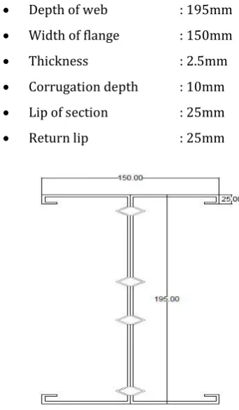
2.1 Specimen Details
The cross section of supacee section is shown in figure 1,
Depth of web : 195mm Width of flange : 150mm
Thickness : 2.5mm
Corrugation depth : 10mm Lip of section : 25mm
[image:1.595.324.495.451.743.2] Return lip : 25mm
© 2018, IRJET | Impact Factor value: 6.171 | ISO 9001:2008 Certified Journal | Page 2851 2.2 Need of Supacee Section
Supacee section is equipped both edge and web stiffener.
This section has a distinct Edge stiffener. It has a return lip feature with a distinct extra projection than conventional 90 degree lip projection.
Stiffener presented at web section is at distinct lengths, which are fixed after several experimental investigations.
This distinctive web cross section (with 4 stiffeners) helps in effectively resisting the local buckling in web region.
Return lip provision present helps in increasing load bearing capacity of the section and reducing the local buckling failure in flange region.
3. ABAQUS SOFTWARE
ABAQUS, It is a software application used for modeling, assembling, analysing and visualizing the finite element analysis result. ABAQUS is a software suite for finite element analysis and computer-aided engineering. ABAQUS provides the most complete and flexible solution to understand the detailed behaviour of a complex assembly, refine concepts for a new design, understand the behaviour of new materials, or simulate a discrete manufacturing process. ABAQUS 6.12 version software is used to create modelling, predict load, displacement, rotation, flexure behaviour for any kind of model.
Every complete finite-element analysis consists of 3 separate stages:
Pre-processing or modelling: This stage involves creating an input file which contains an engineer's design for a finite-element analyzer (also called "solver").
Processing or finite element analysis: This stage produces an output visual file.
Post-processing or generating report, image, animation, etc. from the output file: This stage is a visual rendering stage
3.1 Software Analysis
[image:2.595.317.556.78.235.2]The geometry of any section to be analysed are first modelled under various stages before analysing. This modelling is done to provide necessary details shape of model, dimensions of cross section, their interaction conditions, type of mesh used for meshing, the value of load applied and at which precise location. The column and beam specimen were modelled using a 3D modelling tool. Various iterations have to be given to the beam and column models to achieve its maximum load carrying capacity and its nature of failure at that load
.
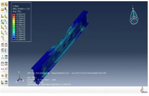
Fig -2: Failure pattern of column
The figure 2 indicate failure pattern of specimen when it is axially loaded from top (column). The area of failure is mainly in flange region. Due the provision of four intermediate stiffeners in web region there is very little damage even after reaching failure condition of the specimen. The maximum deflection value from ABAQUS software is 0.12 mm and ultimate load is 128.5kN. Global buckling occurs along the length of stiffened web section. The deflection increases till the middle section and decreases to the edge portion.
Fig -3: Failure pattern of beam
The figure 3 indicate failure pattern of supacee section on flexural loading condition. Here the area of failure is observed mainly around the area of loading and near support. The cause of failure noted is mainly due to local buckling. This local bucking in flange region leads to collapse of specimen and fail when reaching its maximum load. The maximum deflection value from ABAQUS software is 7.43 mm and ultimate load is 63kN.
4. EXPEIMENTAL ANALYSIS
[image:2.595.314.556.380.536.2]© 2018, IRJET | Impact Factor value: 6.171 | ISO 9001:2008 Certified Journal | Page 2852 provided only on top of the beam member over the flange at
the point of loading. This is done to ensure the load is spread evenly to both flanges of the back to back built up supacee “I” section. Likewise 150*200 mm plates are provided at top and bottom of the supacee column specimen. The supacee channels are connected back to back by 0.5 mm fillet welds at placed equal intervals. The yield strength of the cold formed steel sheets used is 350 N/mm2.
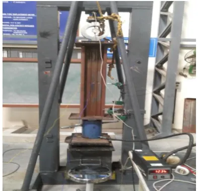
4.1 Flexure Test Set-Up
[image:3.595.57.269.370.556.2] [image:3.595.335.532.380.570.2]Flexural test evaluates the tensile strength of specimen indirectly. It tests the ability of steel beam to withstand failure in bending. The flexural test on beam can be conducted using either two point load test or centre point load test. The testing was carried out in a loading frame of 1000kN capacity. The specimens were tested for flexural strength under two-point loading. In two-point loading test loads were applied at one-third distance from the supports at a uniform rate till the ultimate failure of the specimens occurred. Beam deflections were measured at the centre of the beam using LVDT. The experimental setup is shown in figure 4. Deflection and failure pattern of the beam specimen for flexure test are shown in fig 4.
Fig -4: Experimental test setup for flexure test
Fig -5: Failure pattern of beam
Fig 5 shows the failure pattern of supacee beam. Supacee beam on loading in four point loading condition, experiences deflection. Failure of section is present in the flange region along the area of supports. Nature of buckling experienced is local buckling in flange region.
4.2 Compressive Test Set-Up
Axial loading test evaluates the compressive strength of specimen. It tests the ability of steel column to withstand when loaded in its centroidal axis. Unlike service load conditions, the behaviour of the axially compressed column is fully predictable under ultimate load conditions. As axial loading is increased, axial shortening of the column increases linearly up to about 80% of the ultimate load. The testing was carried out in a loading frame of 1000kN capacity. The specimens were tested for compressive strength. Load was to be applied from one end using a hydraulic jack while the other end is restrained against the frame setup. Here load is applied from the bottom and the restrained condition is met by resting the other end to the loading frame. Load is applied at a steady rate until failure and axial shortening of column were measured using LVDT. The experimental setup is shown in figure 4. Axial deformation of supacee column and its failure pattern are shown in fig 6.
Fig -6: Experimental test setup for compression test
© 2018, IRJET | Impact Factor value: 6.171 | ISO 9001:2008 Certified Journal | Page 2853 Fig 7 shows the failure pattern of supacee column. Supacee
column on loading in axial loading condition, experiences axial shortening. Failure of section is present in the web region along the point of loading. Nature of buckling experienced is distortional buckling in web region and flange at the end of section.
5. RESULTS AND DISCUSSIONS
5.1 Load vs Deflection Curve
Load bearing nature is the ability of a specimen to withstand without failing. This characteristic of a member is very important as this value is the base in designing of a structure.
Chart -1: load vs deflection curve for supacee beam
Load with their corresponding deflection curve is depicted with values obtained from Abaqus software and experimental analysis are shown in chart 1.By experimental result the specimen yield’s at 45 kN with a deflection of 5.15mm and fails at load of 70 kN at a deflection of 7.48 mm. By analytical result the specimen yield’s at 43 kN with a deflection of 5.08mm and fails at load of 63 kN at a deflection of 7.44 mm.
5.2 Load vs Axial Deformation Curve
Chart -2: load vs axial deformation curve for supacee beam
Load with their corresponding axial deformation curve is depicted with values obtained from abaqus software and experimental analysis are shown in chart 2.By experimental
result the specimen yield’s at 200 kN with a deflection of 1.4 mm and fails at load of 255 kN at a deflection of 2.1 mm. By analytical result the specimen yield’s at 162 kN with a deflection of 1.2 mm and fails at load of 208 kN at a deflection of 1.6 mm.
6. CONCLUSION
Supacee section as a flexural member, on analysis bears a maximum load of 70 kN where as conventional cold formed steel I section bears a load within the range of 28 kN to 35 KN for 1.2 meter span.
Supacee section as a compressive member, on analysis bears a maximum load of 255 kN whereas conventional cold formed steel I section bears a load within the range 78 kN to 86 kN for a span of one meter.
Numerical analysis using abaqus software is done to compare the results with experimental analysis. From the comparison we can we can see that the error percentage is less than 20 percent.
This clearly indicates that this supacee section shows enhanced strength when compared to conventional built up I section for both compression and flexural member.
This improved cross section enables the use of this section even as a primary compression member (as a column which cold formed steel section are not used till date) and as purlins and rafters in industrial roofing constructions.
REFERENCES
[1] Ben Young and Ehab Ellobody” Finite element analysis
of cold-formed steel lipped angle compression members”, Advances in Steel Structures, Vol. I
[2] P. Nandini,V.Kalyanaraman “Strength of cold-formed
lipped channel beams under interaction of local, distortional and lateral torsional buckling” ,Thin-Walled Structures 48, 2010.
[3] Mohammad Reza Haidarali and David A. Nethercot
“Local and distortional buckling of cold-formed steel beams with both edge and intermediate stiffeners in their compression flanges”, Thin-Walled Structures 49, 2011.
[4] P. Paczos “Experimental investigation of C-beams with
non-standard flanges“, Journal of Constructional Steel Research 93, 2014.
[5] Ben Young and Gregory J. Hancock” Tests of Channels
© 2018, IRJET | Impact Factor value: 6.171 | ISO 9001:2008 Certified Journal | Page 2854
[6] YuChen, XixiangChen, ChaoyangWang “Experimental
and finite element analysis research on cold-formed steel lipped channel beams under web crippling” Thin-Walled Structures 87 (2015)
[7] Ben Young, Ju Chen” Column tests of cold-formed steel
non-symmetric lipped angle sections”, Journal of Constructional Steel Research 64, 2008.
[8] Hélder D.Craveiro, JoãoPaulo, C.Rodrigues , LuísLaím
“Buckling resistance of axially loaded cold-formed steel columns”, Thin-Walled Structures 106, 2016.
[9] Jia-Hui Zhang, Ben Young “Compression tests of
cold-formed steel I-shaped open sections with edge and web stiffeners”, vol.52, 2011.
[10] Deenadhayalan.S, Iyappan.G.R, Suresh Babu.S”
Experimental Study on Compressive Behavior of Cold Formed Corrugated Steel Section”, IJSRD -Vol. 5, Issue 02, 2017
[11] Yu C, Schafer BW, “Local buckling tests on cold-formed
steel beams” Journal of StructuralEngineering, ASCE 129(12),2003
[12] Put BM, Pi YL, Trahair NS “Lateral buckling tests on
cold-formed channel beams” Journal of Structural Engineering, ASCE 1999;125(5)
[13] Yu C, Schafer BW “Distortional buckling tests on
cold-formed steel beams” Journal of Structural Engineering, ASCE 132(4).,2006
[14] Magnucka-Blandzi E, Magnucki K “Effective design of
cold-formed thin-walled beams with bent edges of flanges” International Colloquium on Stability and Ductility of Steel Structures, SDSS'Rio2010. Brazil: Rio de Janeiro,2010.
[15] Pham CH, Hancock GJ “Shear buckling of thin-walled