Support Vector Machine-based Decision for
Induction Motor Fault Diagnosis using Air-Gap
Torque Frequency Response
Samira Ben Salem
C3S, ESSTT
5, Taha Hussein Street – Tunis Bab Menara 1008, Tunisia
Khmais Bacha
C3S, ESSTT
5, Taha Hussein Street – Tunis Bab Menara 1008, Tunisia
Abdelkader Chaari
C3S, ESSTT
5, Taha Hussein Street – Tunis Bab Menara 1008, Tunisia
ABSTRACT
In this work we propose the air-gap torque as failure signature to detect mechanical faults in particular the eccentricity. In this way, we compare the proposed signature with those most used recently in particular the current space vector (Park vector) and complex apparent power. This signature is subsequently analysed using the classical fast Fourier transform (FFT). The magnitudes of spectral components relative to the studied fault are extracted in order to develop the input vector necessary for the pattern recognition tool based on support vector machine (SVM) approach with an aim of classifying automatically the various states of the induction motor.
General Terms
Diagnostic, Decision, Pattern recognition.
Keywords
Induction motor, fault diagnosis, eccentricity fault, air-gap torque, support vector machine.
1.
INTRODUCTION
Today, the electrical machines are the powerhouse of the industry. Safety, reliability, efficiency and performance are some of the major concerns and needs for electromechanical applications. In this way, early fault detection and diagnosis permit condition-based maintenance to be efficient for the electrical machines during scheduled downtimes. This improves the overal availability and performance while reducing maintenance costs. For the fault detection problem, it is interesting to know if a fault exists in the system via online measurements. For the fault diagnosis problem, it is not only worthwhile to detect if the system has a fault but also to insulate the fault and to find its origin [1].
Many operators use condition-based maintenance strategies in parallel with conventional maintenance schemes. This can reduce unexpected failures and downtimes, can also increase the time between scheduled shutdowns for standard maintenance and can reduce operational costs. Then, the operation of electrical machines in unsafe conditions can be avoided.
The basic faults in three-phase induction motors, that contain a significant percentage of the motor faults, is the eccentricity of stator and rotor. The eccentricity occurs when:
- Elliptical stator inner cross-section.
- Relative misalignment of rotor and stator in the fixing and commissioning stage.
- Wrong placement of ball-bearing. - Rubbing of ball-bearing.
- Misalignment of load axis and rotor shaft. - Mechanical resonance in critical speed. - Unbalanced load and rotor axis slanting [2].
Between the inner stator and outer rotor circumferences, the eccentricity fault causes radial unbalanced magnetic pull (UMP). The direction of the UMP is such that it amplifies the eccentricity.
Due to the eccentricity percentage and the UMP amplitude, the eccentricity in the motor produces a type of fault cycle. This gradually damages the motor due to rubbing of the stator and rotor, and also damages the stator winding and the rotor cage. Any eccentricity in the induction motor structure therefore generates excessive mechanical stress and more rubbing and fatigue of the ball-bearings which gives rise to another type of fault. The interaction of the UMP on the stator core also causes abnormal vibration of the stator winding, which could be dangerous. So, the motor requires eccentricity fault diagnosis and its remedy.
Some consequences of the eccentricity fault in the motor could be [3]:
1. Asymmetry and deviation of air-gap flux, voltages and line currents.
2. Increasing torque and speed variations. 3. Decreasing average torque.
4. Increasing losses and decreasing efficiency. 5. Rising temperature.
For fault diagnosis, some of the above-mentioned consequences or their secondary effects can be used as indices.
In [6] and [7], the air-gap torque was used for detection of electrical faults such as voltage unbalance, the broken rotor barsandthe shorted stator coils in induction motors. In this work we propose to use this signature to detect mechanical faults in particular the eccentricity. In this way, we compare this technique to those most recently used in particular the current space vector (Park vector) and complex apparent power.
This signature is subsequently analysed using the classical fast Fourier transform (FFT). The magnitudes of spectral components relative to the studied fault are extracted in order to develop the input vector necessary for the pattern recognition tool based on support vector machine (SVM) approach with an aim of classifying automatically the various states of the induction motor.
2.
BASIC CONCEPT OF AIR-GAP
TORQUE
Air-gap torque is the torque created by the flux linkages and the currents of induction motor. The rotor, shaft, and mechanical load of a rotating machine constitute a specific spring system that has its own natural frequencies. The attenuations of the air-gap torque components transmitted through the spring system are diverse for different harmonic orders of torque component. Commonly, the air-gap torque curve is different from that of the torque measured from the shaft.
Air-gap torque represents the combined effects of all the flux linkages and currents in both the stator and the rotor of the entire motor. It is sensitive to any unbalance created by defects as well as by unbalanced voltages. Air-gap torque tells distinctively whether the unbalance is caused by air-gap eccentricity, cracked rotor bars or by stator unbalance associated with winding defects and unbalanced voltages. The theoretical foundation for this test is presented for understanding of how the unbalance caused by either rotor or stator defects is detected and distinguished [7].
The air-gap torque equation can be written by (1)
dt
i
i
R
v
i
i
dt
i
i
R
v
i
i
P
Nm
Torque
B A AB A C A C CA B A)
(
)
(
)
(
)
(
3
2
(1)Equation (1) is valid for either Y- or delta-connected motors, where P = number of poles, iA, iB and iC = lines currents, and
R = half of the line-to-line resistance value.
Since the time increment between data points is small, a simple Euler method is used for numerical evaluation of integral in this study.
When static and dynamic eccentricities are present, low frequency components also appear in the line current spectrum, which can be given by [5]:
r mf f p s m f ecf
1 1 (2)
Where f is the fundamental frequency of the supply, fr is the
rotor rotation frequency in rps and m is an arbitrary integer number. When analyzing (1) in the frequency domain, it is clear that beside the previous components, the air-gap torque takes other components at frequencies 2f + kfr, 2f-kfrand kfr.
The latter one (kfr) can be called the eccentricity’s
characteristic components.
3.
BASIC CONCEPT OF SVM
SVM analysis seeks to find an optimal separating hyper-plane by maximizing the margin between the separating data. The regression approximation estimates a function according to a given data set T = {xk, yk}k
m
, where xk denotes the input
vector, yk
1;1
denotes the corresponding output valueand m denotes the total number of data patterns, the SVM regression function is [8]:
1
( )
.
.
0
m k k k
f x
w x b
w x
b
(3)Where w denotes the weight vector and b denotes the bias term. W and b are used to define the position of the separating hyper-plane by which should satisfy the constraints:
2
( .
) 1 ,
1, 2,...,
1
min
2
k k
y w x
b
k
m
w
(4)According to Lagrangian principle, the above problem can be transformed to its corresponding form as follows:
1
1
( , , )
(
) 1
2
m
T T
k k k k
L w b
w w
y w x
b
(5)Where αk are the Lagrange coefficients (αk >0).
According to the condition of optimality:
( , , )
( , , )
0,
0
L w b
L w b
w
b
(6)We have the following equations:
1
1
. .
.
0
m
k k k k
m k k k
w
x y
y
(7)Hence, from Eqs. (5) and (7), the dual problem is:
1 ,
1
1
max
(
)
2
,
0
0
m
k k j k j k j
k k j
k m
k k i
y y x x
k
y
(8)We define the support vectors VS any vector xk as:
0 0
. (
. )
1
k k
This is equivalent to Eq. 10:
k k0
VS
x
for k = 1,2, …., m (10)The ranking function class(x) is defined by Eq. 11:
0 0
0( )
( . )
( . )
i n
i i i x VS
class x
sign w x
b
sign
y x x
b
(11)
If class (x) is less than 0, x is the class -1 else it is a Class 1. However for nonlinear cases, there is insufficient space for classifying the inputs. So, we need a larger space. We must therefore resolve Eq. 12:
1 ,
1
1
max
(
) (
)
2
, 0
0
m
k k j k j k j
k k j
k m
k k k
y y
x
x
k
C
y
(12)
With C is the margin parameter.
( ,
k j)
(
k). (
j)
K x x
x
x
is a positive kernel function definite on Rn based on Mercy condition.From the above analysis, it can be concluded that SVM is decided by training samples and kernel function. The construction and selection of kernel function is important to SVM. But the kernel function is often given directly in practice.
Some common kernel functions are shown as follows:
The linear Kernel function :
K x x
( , ')
x x
. '
(13) The polynomial kernel function:
( , ')
( . ')
dK x x
x x
or(
c
x x
. ')
d (14) Gaussian radial basis function :
2
2
'
( , ')
exp(
)
2
x
x
K x x
(15) Sigmoïd kernel function :
K x x
( , ')
tanh(
0( , ')
x x
0)
(16)4.
EXPERIMENTAL RESULTS
4.1
Test bench description
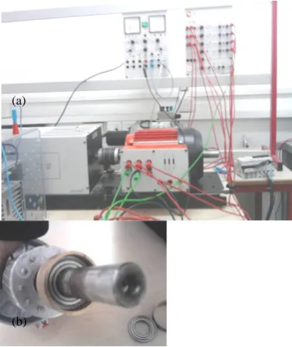
The test motor used in the experimental investigation was a three-phase 50-Hz, four-pole, 28 rotor bars, 1.1-kW induction machine (Fig.1-a). The induction machine shaft is mounted with a powder brake in order to simulate different level of load torque during the tests. In order to create an air-gap eccentricity fault in the induction motor, a simple mechanism
was used. Each of the two bearing housings of the rotor was changed to a pair of eccentric rings placed one into the other (Fig.1-b).
[image:3.595.317.522.243.487.2]Three phase current sensors and three voltage sensors are used to monitor the induction machine during operation at steady state. Low-pass anti-aliasing filters are implemented in order to set the frequency bandwidth of the analysed signals to a correct range. Then, the outputs of the low-pass filters are directly connected to a data acquisition board (dSpace DS1104 processor board) which contains a Motorola Power PC 603e model and a DSP (TMS320F240 – 20 MHz). The process can be commanded and monitored via the Control Desk software of dSpace. The data sampling is performed using differential channels and a sampling frequency of 10 kHz. The software used is MATLAB™ for the data acquisition and processing.
Fig.1. Experimental set-up of 1.1 kW to collect healthy and faulty induction machine data.
In order to test the efficiency of the proposed diagnostics techniques, the proposed fault signatures are analysed in the frequency domain. The Blackman window is chosen because it gives the best compromise between the relative side lobe attenuation and the main lobe width, in order to differentiate the analysed frequency components used by the tested diagnosis methods. The choice of the Blackman window is detailed in [9].
4.2
Experimental results
Analytical methods show that for eccentricity fault, the following harmonics exists in the above mentioned diagnosis media (air-gap torque, current space vector and complex apparent power): kωr , 2ω+kωr and |2ω-kωr| .
To show the efficiency of the proposed method, some selected spectra are presented. It can be seen that the spectral components coincide with the predicted values. The first step of the diagnosis method is the detection of rotational frequency fr. In figure 2, we observe the complex apparent power, space
vector current and the air-gap torque frequencies spectrum at 24.4 Hz (fr) with eccentricity fault. We can deduce that the
air-gap torque offers the best sensitivity. (a)
Fig. 2. Different diagnosis media spectrum with eccentricity fault around rotor rotation frequency.
Table 1. Frequencies components of eccentricity faults
K kfr (Hz)
[image:4.595.322.537.178.465.2] [image:4.595.82.252.279.410.2] [image:4.595.73.258.497.638.2] [image:4.595.336.522.594.740.2]2f+kfr (Hz)
|2f-kfr| (Hz)
1 24.4 124.4 75.6
2 48.8 148.8 51.2
3 73.2 173.2 26.8
4 97.6 197.6 2.4
5 122 222 22
6 146.4 246.4 46.4
7 170.8 270.8 70.8
8 195.2 295.2 95.2
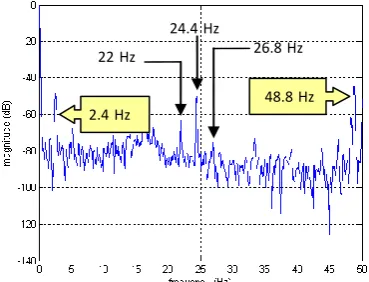
Fig. 3, shows clearly the air-gap torque frequencies components at 2.4 Hz, 22 Hz, 24.4 Hz, 26.8 Hz and 48.8 Hz. It can be seen that the spectral components coincide with the predicted values summarized in Table.1. Theirs magnitudes are illustrated and compared with current space vector and complex apparent power magnitudes in Table.2.
Fig. 3. Air-gap torque frequency spectrum with eccentricity fault in full load case in range [0Hz - 50Hz]
It is clear that the different magnitudes of the spectral components have been affected by the eccentricity fault. The magnitudes of these components were proven to be a very good diagnostic index.
In Table 2 the sensitivity of the studied diagnosis media are presented. We can conclude that the air-gap torque have the best sensitivity for the eccentricity fault in frequency range [0 Hz -50 Hz].
Fig.4 confirms the weakening effect of the motorloading on the amplitudes of some components, particularly the low frequency components. It also shows that for the low level of loads the characteristic frequencies of eccentricity faults will be not easily detectable because they approach until the coincidence with the spectral lines characteristic of the power supply.
Table 2. Amplitude of different frequency components of eccentricity faults in range [0Hz – 50Hz].
f(Hz) A(dB) Complex apparent
power
A(dB) Air-gap torque
A(dB) current space vecteur
2.4 -56.9 -48.61 -56.8
22 -66.25 -63.16 -66.24
24.4 -65.55 -51.11 -65.79
26.8 -81.2 -75.6 -81.31
48.8 -49.12 -44.42 -49.05
Fig. 4. Effect of the load level on the eccentricity fault frequency component detection
In fig. 5 it can be observed that two side-bands frequencies components are present in the air-gap torque spectrum around 100Hz, their magnitudes reflect the severity of the rotor asymmetry, in this case we have an inherent or incipient rotor fault. The left-side component (2f-2fs) is caused directly by the rotor fault while the right-side component (2f+2fs) is caused by the consequent speed ripple. The eccentricity fault frequency component 97.6 Hz (4fr) coincide with the left side-band
component caused by the rotor asymmetry.
Fig.5. Air-gap torque frequency spectrum with eccentricity fault around 100 Hz
124.4Hz
95Hz
122Hz (2f+2fs) (2f-2fs)
(75% of full load) (50% of full load)
(25% of full load) (0% of full load)
2.4Hz
48.8Hz 24.4Hz
Figs. 6, 7, 8 and 9 show clearly the air-gap torque frequencies components at 73.2 Hz, 75.6 Hz, 95.2 Hz, 122 Hz, 124.4 Hz, 148.8 Hz, 195 Hz, 197.6 Hz and 295.2 Hz. It can be seen that the spectral components coincide with the predicted values summarized in Table.1.
[image:5.595.72.259.328.472.2]Fig. 6. Air-gap torque spectrum with eccentricity fault in range [50Hz - 90Hz]
[image:5.595.316.543.373.497.2]Fig. 7. Air-gap torque spectrum with eccentricity fault in range [125Hz - 175Hz]
Fig. 8. Air-gap torque spectrum with eccentricity fault in range [190Hz - 230Hz]
Fig.9. Air-gap torque spectrum with eccentricity fault in range [290Hz - 320Hz]
The magnitudes of the frequencies components related to eccentricity fault for different diagnosis media are summarized in Table 3. We can deduce that the air-gap frequencies components have the best sensitivity for the eccentricity fault in frequency range [70 Hz -300 Hz].
Table 3. Amplitude of different frequencies components of eccentricity faults in range [50Hz – 300Hz]
f (Hz) A(dB)
Complex apparent power
A(dB) Air-gap torque
A(dB) Current space vector
73.2 -75.18 -75.84 -75.22
75.6 -88.03 -83.4 -87.76
95.2 -84.22 -76.9 -82.69
122 -80.44 -83.4 -80.71
124.4 -84.65 -77.92 -87.46
148.8 -86.7 -83.5 -89.25
195 -76.63 -79.63 -76.22
197.6 -76.71 -76.18 -76.34
295.2 -62.3 -59.11 -62.37
4.3
Induction motor faults classification
based on SVM
According to this comparative study, we propose to use the spectrum of the air-gap torque in the frequency range [0Hz, 300Hz] like failure signature for the eccentricity fault because it offers the best sensitivity. In this interval, we can observe the frequencies components coming from kfr, 2f+kfr and |2f-kfr|.
Initially we detect the rotational frequency component fr and its
amplitude, and then we calculate the frequencies components kfr, 2f+kfr and |2f-kfr| and we determine their amplitudes in the
interval [0Hz, 300Hz]. The amplitudes of these components can be a good index for the eccentricity fault detection. The magnitudes of air-gap torque spectral components relative to the studied faults are extracted in order to develop the input vector necessary for the pattern recognition tool based on support vector machine (SVM) approach with an aim of classifying automatically the various states of the induction motor.
This vector must characterize the failure signature and consequently the state of the machine. It is created by the magnitudes of the air-gap torque spectral components relative to the studied faults (broken rotor bar and eccentricity). The vector is expressed by (17).
148.8 Hz
295Hz
195Hz
[image:5.595.70.257.501.648.2](2
2
)
(2
2
)
(
)
(2
)
(5 )
(8 )
(2
)
( 2
)
(2
8 )
( 2
4
)
(2
2
)
( 2
5
)
r r r r
r r r r r r
mag
f
fs
mag
f
fs
mag f
mag
f
mag
f
mag
f
V
mag
f
f
mag
f
f
mag
f
f
mag
f
f
mag
f
f
mag
f
f
(17)
The first stage in the recognition process is to create a database. It can be accomplished by analysing the magnitudes of the air-gap torque spectral components for the classes which represent the states of the induction machine. Here, there are three possibilities examined as following: machine operating without defect, machine operating with broken rotor bar and machine operating with an air-gap eccentricity fault, All these situations have been tested under 0%, 25%, 50%, 75% and 100% of the rated load. The data are divided into two data sets: the training data set (60 samples) and the testing data set (40 samples).
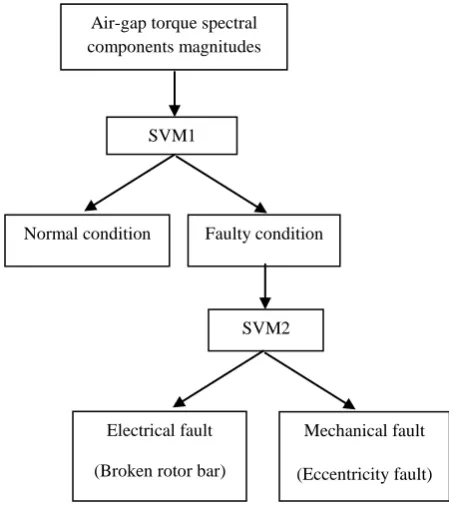
[image:6.595.71.173.71.286.2]As shown in Fig. 10, the diagnostic model includes two SVM classifiers which are used to identify the three states: normal state, electrical fault (broken rotor bar) and mechanical fault (eccentricity). With all the training samples of the states, SVM1 is trained to separate the normal state from the fault state. When input of SVM1 is a sample representing the normal state, output of SVM1 is set to +1; otherwise -1. With the samples of single fault, SVM2 is trained to separate the mechanical fault from the electrical fault. When the input of SVM2 is a sample representing electrical fault, the output of SVM2 is set to +1; otherwise-1.
Table 4. Codification output of SVM.
svm1 svm2
Normal condition +1
Broken rotor bar -1 +1
eccentricity fault -1 -1
[image:6.595.328.553.73.330.2]All the two SVMs adopt polynomial and Gaussian as their kernel function. In SVM, the parameters σ and C of SVM model are optimized by the cross validation method. The adjusted parameters with maximal classification accuracy are selected as the most appropriate parameters. Then, the optimal parameters are utilized to train the SVM model. So the output codification is presented in table 4.
Fig. 10. Induction motor fault diagnostic model based on SVM classifiers
Fig. 11. Proposed method implementation basic steps
The training procedure and choice of SVM parameters for training are very important for classification. Fig. 11 presents the process of optimizing the SVM parameters with the cross validation method. The false alarm rate and the non-detection rate of diagnostic systems for different membership functions are illustrated in table 5. From table 5, we note that the Gaussian kernel function shows highly accurate classification of fault diagnosis procedure. A classification rate of the fault diagnosis is 92.5%.
Air-gap torque spectral components magnitudes
SVM1
Normal condition Faulty condition
SVM2
Electrical fault (Broken rotor bar)
Mechanical fault (Eccentricity fault)
Air-gap torque spectral components magnitudes
Initialization
(Initial parameters)
Training SVM model
Cross validation
Optimal values of C and σ parameters obtained
Training data set Testing data set
Learning SVM Testing and
[image:6.595.71.262.560.656.2]Table 5. The SVM classification performance.
SVM kernel function
False alarm rate (%)
Non-detection rate (%)
Polynomial 5% (2 / 40) 10% (4 / 40) Gaussian 0% (0 / 40) 7.5% (3 / 40)
5.
CONCLUSION
In this work we propose to use the air-gap torque to detect mechanical faults in particular the eccentricity. In this way, we compare this technique with those most used recentlyin particular the current space vector (Park vector) and complex apparent power. This signature is subsequently analysed using the classical fast Fourier transform (FFT).The proposed failure signature shows its effectiveness and its robustness in both electrical and mechanical fault detection. In order to obtain a more robust diagnosis, it is proposed a support vector machine (SVM) suitable to online identification of induction machine faults: broken rotor bar (electrical fault) and eccentricity fault (mechanical fault). The input patterns to train the SVM are obtained using experimental data related to healthy and faulty machines under several load rates. The inputs of the SVM are very important for successful fault detection. In this work, we extract only the air-gap torque spectral components magnitudes relative to the studied faults.
6.
REFERENCES
[1] M.-Y.Chow, "Guest editorial special section on motor fault detection and diagnosis", IEEE Transactions on Industrial Electronics, vol.47, n°5, October 2000, pp.982-983.
[2] W.Thomson, M.Fenger, "Current signature analysis to detect induction motor faults", IEEE Industry Applications Magazine, July/August 2001, pp.26-34.
[3] Jawad Faiz, Mansour Ojaghi, "Different indexes for eccentricity faults diagnosis in three-phase squirrel-cage induction motors: A review ", Mechatronics 19 (2009) pp 2–13
[4] Jee-Hoon Jung, Jong-Jae Lee, and Bong-Hwan Kwon, "Online Diagnosis of Induction Motors Using MCSA" IEEE Transactions On Industrial Electronics, Vol. 53, No. 6, December 2006 pp 1842-1852
[5] M’hamed Drif and A. J. Marques Cardoso, "Air-gap-Eccentricity Fault Diagnosis, in Three-Phase Induction Motors, by the Complex Apparent Power Signature Analysis", IEEE Transactions On Industrial Electronics, Vol. 55, No. 3, March 2008 pp 1404-1410
[6] K. Bacha, M. Gossa, G-A. Capolino, Comparative Investigation of Diagnosis Media of Stator Voltage Unbalance and Rotor Broken Bars in Induction Motor. In Proceedings of IEEE Industrial Electronics -IECON’2006 – 32nd
annual conference on. 6-10 NOV 2006. pp 5040-5045 Paris (France)
[7] J.S. Hsu, "Monitoring of defect in induction motors through air-gap torque observation", IEEE Transactions on Industry Applications, vol.31, n°6, september/october 1995, pp.1016-1021.
[8] K. Bacha, S. Souahlia, M. Gossa, "Power transformer fault diagnosis based on dissolved gas analysis by support vector machine", Electric Power Systems Research 83 (2012) 73-79.
![Fig. 6. Air-gap torque spectrum with eccentricity fault in range [50Hz - 90Hz]](https://thumb-us.123doks.com/thumbv2/123dok_us/8125844.795467/5.595.73.260.139.281/fig-air-gap-torque-spectrum-eccentricity-fault-range.webp)