5
III
March 2017
Technology (IJRASET)
Power Dispatching of Active Generators Using
Droop Control in Islanded Micro-Grid
Lekkala Sravan Kumar1, Pudi Sekhar2
1
Electrical & Electronics Engineering Department,
2
Vignan’s Institute of Information Technology
Abstract: The Microgrid(MG) concept allows small distributed energy resources (DERs) to act in a coordinated manner to provide a necessary amount of active power and ancillary service when required. This paper presents control and power management of electronically interfaced Distributed Energy Resource (DER) units for microgrids. Voltage and frequency regulation in an islanded microgrid is one of the main control requirements. In this work, inverter control method for islanded operation of microgrid for the renewable resources has been studied. First task of the study was development of a Voltage Source Converter (VSC) system. Active and reactive power control systems for power dispatching have been implemented in the VSC and so that it can work as an active generator. The power dispatching policy of the active generator is based on combination of droop and PI control method. This paper presents results from a test microgrid system considering of a voltage sourced converter VSC interfacing with a DG under varying load conditions. The model has been simulated in MATLAB/Simulink and stable operations have been observed where micro-grid frequency, voltage and power quality were within acceptable ranges.
Keywords— Active generators, Distributed generation (DG), Droop control, Micro-grid (MG), Voltage source converters (VSC)
I. INTRODUCTION
The Microgrid (MG) is a collection of distributed generators or micro resources, energy storage devices, and loads which operate as a single and independent controllable system capable of providing both power and heat to the area of service [1]. The micro resources that are incorporated in a Micro-Grid are comprised of small units, less than 100 kW, provided with power electronics (PE) interface. Most common resources are Solar Photovoltaic (PV), Fuel Cell (FC), or micro turbines connected at the distribution voltage level. In a Micro-Grid, the micro sources and storage devices are connected to the feeders through the micro source controllers (MCs) and the coordination among the micro sources is carried out by the central controller (CC) [2]. The Micro-Grid is connected to the medium voltage level utility grid at the point of common coupling (PCC) through the circuit breakers. When a Grid is connected to the grid, the operational control of voltage and frequency is done entirely by the grid; however, a Micro-Grid still supplies the critical loads at PCC, thus, acting as a PQ bus. In islanded condition, a Micro-Micro-Grid has to operate on its own, independent of the grid, to control the voltage and frequency of the Micro-Grid and hence, acts like a PV (power-voltage) bus. The operation and management in both the modes is controlled and coordinated with the help of micro source controllers (MCs) at the local level and central controller (CCs) at the global level.
DGs encompass a wide range of prime-mover technologies, such as internal combustion engines, gas turbines, wind power, micro turbines, photovoltaic (PV), fuel cells, etc. But controlling a potentially huge number of DGs creates a daunting new challenge for operating and controlling the network safely and efficiently [3]. This challenge can be partially addressed by microgrids. Microgrid can operate in two modes: grid-connected mode and island mode. In normal grid-connected mode, power will be supplied to loads either though the main grid or the microgrid; however when there is a need for the Islanded operation the Microgrid can be switched
to Islanded mode of operation. Different from traditional utility grid, a microgrid contains DGs through VSC to interface with
utility. The VSC have more controlled variables than the commonly used synchronous generators [4]. Thus one of the key problems in microgrid operation is to determine control strategies. When loads change or disconnection occurs, controllers need to coordinate DGs to guarantee power quality and demand in the microgrid. In [5], decentralized control using multi-agent systems approach is proposed by using only the local information of DGs. The decentralized architecture of the microgrid is equipped with power electronic interfaces and all the agents are equal and autonomous, and they only communicate with their neighbours to achieve power balancing and thus maintain voltage and frequency. However this method requires large amount of communication which increases the complexity when implemented for control.
Technology (IJRASET)
control configuration of a microgrid is proposed. In grid-connected mode all DGs are equipped with PQ controllers, and under islanded mode only the master inverter switches to V/f control to maintain the Microgrid voltage level and frequency. The drawback of master-slave method is that it also takes large amount of communication. In practical microgrid operation, controllers for different types of DGs vary extensively. For example, micro turbines and fuel cell can be equipped with either PQ controller in order to follow real and reactive power references or V/f controller which maintains stability of microgrids voltage and frequency; however for renewable energy DGs such as wind turbine and PV, due to their intermittence, PQ controller will have to be used to maximize renewable energy.
In order to operate microgrid under islanded mode effectively by satisfying the load demand and voltage/frequency stability, while minimizing the communication between DGs in Microgrid control, a droop control strategy is proposed in this paper. The control strategies presented here is to overcome the drawback of pure V/f control which leads to the failure of responding to load changes and the drawback of master-slave control which requires certain amount of DG communication. The use of droop characteristics concepts is commonly used in controlling generating units in power system [8].
The rest of the paper is organized as follows: The Section II describes the proposed structure of the Micro-Grid and its control. The Section III presents the simulation results and discussion. Finally the concluding remarks are provided in Section IV.
II. MICRO-GRIDSTRUCTUREANDCONTROLLERDESIGN
A. Micro-Grid Structure
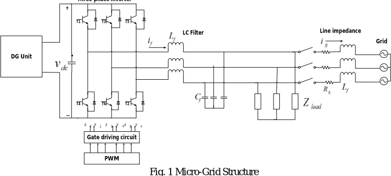
In order to study the operation of the Microgrid with the droop control technique a Microgrid is designed as shown in Fig.1. The Micro-Grid contains a DG which can be fuel cells, PV, wind turbines or energy storage system, etc. Every DG connected to the micro-grid AC bus through a static switch. The micro-grid connected to the main grid via a smart switch (SS). The DG is connected to voltage source inverters (VSI) controlled by pulse width modulation (PWM). LC filter are connected to the system to filter high frequency noise. A load is also connected to realize the droop control technique.
Three phase inverter
LC Filter Line impedance
T1 T3 T5
T4 T6 T2
+
_ DG Unit
Gate driving circuit
PWM
[image:3.612.97.498.368.549.2]Grid
Fig. 1 Micro-Grid Structure
B. Controller Design
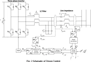
To convert a VSC to an active generator, droop control systems have to be implemented in the VSC control system. Basically VSCs can be controlled as current mode control, where VSCs have to synchronize with the grid voltage waveform and can provide power to the grid by controlling its current output. However, when VSCs are not connected to the grid but directly to a load, it has to produce its own AC waveform to operate its loads. In this case inverter has to generate and control its output voltage waveform and works in voltage control mode. The power dispatching policy of the active generator is based on combination of droop and PI control method. Fig .2 represents the schematic of droop control.
Technology (IJRASET)
abc dq
Power calculations
Voltage and Current controller
Droop Control Voltage
formation abc
dq
abc
dq abc
dq PWM
Three phase inverter
LC Filter Line impedance
T1 T3 T5
T4 T6 T2
+
[image:4.612.127.503.78.335.2]_
Fig. 2 Schematic of Droop Control
With reference to Fig. 2, the , are measured and converted to , and , components which are used to calculated the
active and reactive powers.
The axis output voltage and current measurements are used to calculate the instantaneous active power ( ) and reactive power
generated by the inverter using equations (1) and (2) as shown in Fig. 3.
=3
2 + (1)
=3
2 + (2)
Fig. 3 Power calculation Block
During islanded operation, the inverter does not have externally generated reference signals. As a result, the inverter must generate its own frequency and voltage magnitude references using the droop equations. The references are generated using conventional
− and − droop equations as in (3) and (4). The Fig. 4 shows the droop characteristics.
Voltage and frequency droop control method can be defined as [11]:
= ∗+ ( − ∗) (3)
= ∗+ ( − ∗) (4)
Where P* and Q* are the reference real and reactive power, f* and V* are the grid rated angular frequency and voltageamplitude, f
[image:4.612.178.431.412.579.2]Technology (IJRASET)
Active power frequency
[image:5.612.114.501.79.247.2]Reactive power voltage
Fig. 4 Droop Characteristics
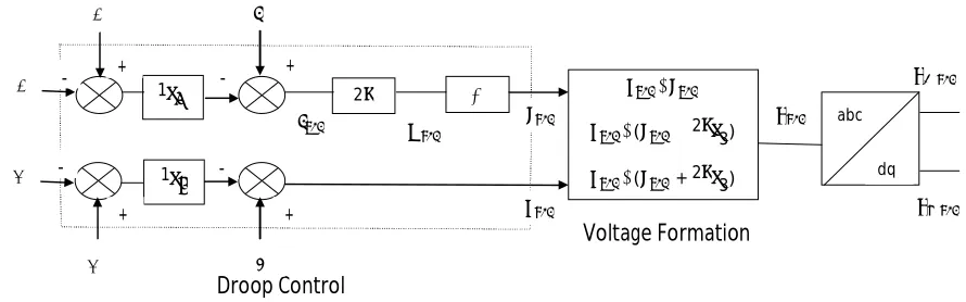
As shown in Fig. 5, the measured P and Q, reference ∗ and ∗, nominal ∗ and ∗ are considered as the input to calculate the
reference _ and _ . _ and _ are reference voltage at and axis respectively.
∠
∠( −2 3)
∠( + 2 3)
∫
2 1
1
abc
dq
Droop Control
Voltage Formation
_
_ ∗
∗
∗
∗
+ +
+ +
-
- -
-
Fig.5 Droop control and Voltage Formation Block
In Fig.5, ∗ and ∗ are grid rated frequency and voltage magnitude, respectively. and are reference frequency and voltage
magnitude, and they are obtained by droop control characteristic. Three-phase is obtained and then converted into _ and
_ by Park’s transformation.
Now and from Eq. (5) and (6) respectively will be used to generate a tracking signal for inner control loops.
= (5)
= (6)
Where is a reference or tracking signal for Voltage & Current control loops.
The voltage controller uses PI controller and current controller uses P controller to generate the required reference signals. The generated reference signals are used as reference signals for PWM generated to generate the required PWM pulses.
III. SIMULATIONRESULTSANDDISCUSSION
In order to study effectiveness of the droop controller, the Microgrid structure shown in the Fig .2 is implemented using MATLAB/Simulink.
[image:5.612.89.534.290.429.2]Technology (IJRASET)
Load 1 P=20KW, Q=10KVar
Load 2 P=20KW, Q=10KVar
Load 3 P=20KW, Q=10KVar
DG P=75KW, Q=70KVar, V=800V
Droop control m=1e-5, n=3e-4
LC filter =0.01ohms, =0.6mH, =1500µF
Load 1 (P=20kW, Q=10KVar) is connected for time t=0s to t=1s. Load 2 (P=20kW, Q=10KVar) is connected for t=0.4s to t=1s and Load 3 (P=20kW, Q=10KVar) is connected for t=0.6s to t=0.1s.
t=0s to t=0.4s, the load on the system is P=20kW and Q=10kVar. Then Load frequency is 50.4Hz and Voltage is 380 and the
current is 50A. For t=0.4s to t=0.6s the load is P=40kW and Q=20kVar. Load frequency is 50.2Hz and Voltage is 380 and the
current is 100A. For t=0.6s to t=1s the load is P=60kW and Q=30kVar. Fig .6 shows the Active and reactive power dispatching for an Active generator. As shown in Fig .6, Controller for DG has quick response and tracks the references effectively. The real and reactive power can be controlled independently because of the decoupling of the reference currents. Fig. 7, Fig. 8 shows the change in the Frequency, Voltage, and Current with respect to the load.
Fig.6 Active and Reactive Power Outputs
Fig.7 change in the Frequency
0 0.1 0.2 0.3 0.4 0.5 0.6 0.7 0.8 0.9 1
0 2 4 6 8x 10
4
Time (Se c)
A ct iv e P o w er ( K W )
Active and Reactive Powers
0 0.1 0.2 0.3 0.4 0.5 0.6 0.7 0.8 0.9 1
-1 0 1 2 3 4x 10
4
Time (Se c)
R ea c ti v e P o w e r (K V a r) P Q Q=10KW Q=20KW Q=30KW P=60KW P=40KW P=20KW
0 0.1 0. 2 0.3 0.4 0.5 0.6 0.7 0.8 0.9 1
50 50.1 50.2 50.3 50.4 50.5 50.6 50.7
Time (Se c)
Technology (IJRASET)
Fig.8 Load Voltage and Load Current
IV. CONCLUSION
In this paper, droop controller is developed for inverter interfaced DGs. The power dispatching of active generators using droop control is implemented and is simulated. The use of droop control ensures that DGs can generate certain power in accordance with real and reactive power references. Droop controller is developed to ensure the quick dynamic frequency response when a forced isolation occurs or load changes. Compared to pure V/f control and master-slave control, the proposed control strategies which have the ability to operate without any online signal communication between DGs make the system operation cost-effective and fast respond to load changes. The simulation results obtained shows that the proposed controller is effective in performing real and reactive power tracking, voltage control in islanded mode.
REFERENCES
[1] R.H. Lasseter, “MicroGrids,” in Proc. IEEE Power Engineering Society Winter Meeting, vol. 1, pp. 305–308, 2002.
[2] S. Chowdhury, S.P. Chowdhury, and P. Crossley, “Microgrids and Active Distribution Networks,” IET Renewable Energy Series 6, 2006.
[3] N. Hatziargyriou, H. Asano, R. Iravani and C. Marnay, “Microgrids,” IEEE Power & Energy Magiazine,vol.5, no.4, pp. 78-94, 2007.
[4] K.T. Tan, P.L. So, and Y.C. Chu, “Control of parallel inverter–interfaced distributed generation systems in microgrid for islanded operation,” IEEE Conf. Probabilistic Methods Applied to Power Systems, pp.1-5, 2010.
[5] N. Cai and J. Mitra, “A decentralized control architecture for a microgrid with power electronic interfaces,” IEEE conf. North American Power Symposium,
pp. 1-8, 2010.
[6] S. Barsali, M. Ceraolo, P. Pelacchi, and D. Poli, “Control techniques of dispersed generators to improve the continuity of electricity supply,” IEEE Conf. Power Engineering Society, vol.2, pp.789-794, 2002.
[7] X. Chen, Y.H. Wang, and Y.C. Wang, “A novel seamless transferring control method for microgrid based on master-slave configuration,” IEEE Conf. ECCE
Asia, pp. 351-357, 2013.
[8] P. Kundur, “Power system stability and control,” McGraw-Hill, New York, 1993.
[9] M. Prodanovic, “Power Quality and Control Aspects of Parallel Connected Inverters in Distributed Generation,” Ph.D. dissertation, Imperial College, Univ.
London, London, UK, 2004.
[10] M. N. Marwali and A. Keyhani, “Control of distributed generation systems—Part I: voltages and current control,” IEEE Trans. on Power Electron., vol. 19,
no. 6, pp. 1541–1550, 2004.
[11] J.M. Guerrero, J.C. Vasquez, J. Matas, L.G. Vicuna, and M. Castilla, “Hierachical Control of Droop-Controlled AC and DC microgrid-A general approach
toward standardization,” IEEE Trans. on Industrial Electron., vol. 58, no.1, pp. 158-172, 2011.
0 0.1 0.2 0.3 0.4 0.5 0.6 0.7 0.8 0.9 1
-400 -200 0 200 400 Time (sec) V o lt a g e (V )
Load Voltage and Load Current
0 0.1 0.2 0.3 0.4 0.5 0.6 0.7 0.8 0.9 1