iv DESIGN OF REFLECTARRAY ANTENNA INTEGRATED WITH FSS TEXTURED CONFIGURATIONS FOR WIRELESS COMMUNICATION
APPLICATIONS
ARSLAN KIYANI
A thesis submitted in
fulfillment of the requirement for the award of the Degree of Master of Electrical Engineering
Faculty of Electrical and Electronics Engineering Universiti Tun Hussein Onn Malaysia
ABSTRACT
Modern communication systems require intelligent antenna arrays to achieve increased phase range for the performance improvement. Moreover the design
requirements of spacecraft antennas for satellite communications and
telecommunication missions require multifunction antennas to prevent the propagation of electromagnetic waves in certain frequency bands. This project investigates the feasibility of employing reflectarray antenna integrated with FSS textured configurations to combat the scan blindness problem. Performance investigation of different strategic resonant elements has been carried out in X-band frequency range by using commercially available computer models of CST MWS and Ansoft HFSS based on Finite Integral Method (FIM) and Finite Element Method (FEM) respectively. Frequency Selective characteristics are also exploited by embedding the dipole, square loop and triangular loop resonant elements on top of the groundless substrate. Integrated FSS Reflectarray (FSS-RA) configurations based on iterative loop length approach are than implemented for operation in both X and Ku-band to improve the static phase range for the reduction of phase errors resulting in scan blindness. It has been demonstrated that the maximum static phase range of 540° can be obtained with the loop length variation of 6.8mm. Moreover novel algorithms based on mathematical models have been developed for the calculation of progressive phase distribution depicted by each individual resonant element and resonant frequency estimation of FSS reflectarrays. In order to validate the authenticity of numerical results waveguide scattering parameter measurements have been carried out by fabricating two patch unit cells for each reflectarray resonant element. Measured results demonstrated that reduction in reflection area of resonant
elements from 105.74mm2 to 7.33mm2 tends to increase the reflection loss values
TABLE OF CONTENTS
CHAPTER 1 INTRODUCTION AND BACKGROUND
1.1. Problem statement 3
1.2. Objectives of the research work 3
1.3. Scopes of the research work 4
1.4. Operation principle of reflectarray antenna 4
1.5. Advantages of reflectarray antenna 6
1.6. Disadvantages of reflectarray antenna 7
1.6.1 Bandwidth performance 7
1.6.2 Phase error compensation considerations 9
1.6.3 Scan blindness 9
1.7. Frequency Selective Surfaces (FSSs) 10
1.8. Reflectarray integration with FSS 10
1.9. Progress towards FSS planar reflector antennas 11
1.10. Flow of thesis 13
CHAPTER 2 THEORETICAL BACKGROUND AND LITREATURE REVIEW
2.1. Reflectarray cell element configurations 14
2.2. Reflectarray analysis techniques 16
2.2.1 Full wave analysis 17
2.2.2 Infinite array analysis 18
2.2.4 Extended local periodicity (ELP) approach 19
2.3. Performance parameters of reflectarray 20
2.3.1 Reflection loss and 10% bandwidth 20
2.3.2 Reflection phase and Figure of Merit (FoM) 23
2.4. Reflectarray bandwidth limitations 24
2.5. Multilayer reflectarray configurations 24
2.6. Reflectarray scan blindness limitations 28
2.7. Frequency Selective reflectarray configurations 28
CHAPTER 3 OVERVIEW OF RESEARCH METHODOLOGY
3.1. Phase I: Literature review, validation work and preliminary analysis 33
3.2. Phase II: Reflectarrays integration with FSS 33
3.3. Phase III: Stacked layer reflectarray configurations 34
3.4. Phase IV: Numerical analysis for mathematical modeling 34
3.5. Phase V: Scattering parameter measurements 35
CHAPTER 4 VALIDATION AND ANALYSIS OF REFLECTARRAYS AND
FREQUENCY SELECTIVE SURFACES (FSS)
4.1. Reflectarray validation work 37
4.1.1 Implementation using CST Microwave Studio 37
4.1.2 Multilayer reflectarray design specifications 37
4.1.3 Results without ground plane 39
4.1.4 Results with ground plane separated by 0.1 λ 42
4.1.5 Discussion 44
4.2. Frequency Selective Surface (FSS) validation work 44
4.2.1 Implementation using Ansoft HFSS 45
4.2.2 Design specifications 45
4.2.3 Results comparison for three unit cell geometries 47
4.3.1 Built model of unit cell reflectarray 53
4.3.2 Effects of material properties on the performance of reflectarray antenna 54
I. Reflection loss curves 55
II. Bandwidth and FoM 57
III. Reflection phase curves 57
IV. Bandwidth and phase range 59
4.3.3 Effect of substrate thickness on the performance of reflectarray
antenna 60
I. Reflection loss curves 60
II. Reflection phase curves 62
4.3.4 Performance of reflectarray antenna based on different strategic
resonant element configurations 64
I. Reflection area of resonant elements at 10GHz 64
II. Incident electric fields and surface current density 66
III. Reflection loss and reflection phase curves 69
IV. Mathematical model for progressive phase distribution 72
4.3.5 Frequency Selective Reflectarrays FSS-RA 76
I. Design considerations based on computer simulation tools 76
II. Results and discussion 78
4.3.6 Stacked layer reflectarray configurations 81
I. Reflection loss and reflection phase curves 82
II. Surface current density on loop elements 84
III. Numerical model for stacked layer reflectarray configuration 86
CHAPTER 5 FABRICATION AND MEASUREMENTS
5.1. Waveguide simulator 88
5.2. Two patch unit cell reflectarrays 89
5.4. Measurement setup for reflectarrays 92
5.5. Comparison of simulated and measured results 93
5.6. Measurement setup for FSS-RA 98
5.7. Comparison of simulated and measured results 99
CHAPTER 6 CONCLUSION AND FUTURE WORKS
6.1. Conclusion 102
6.2. Future Works 107
APPENDICES 112
Appendix A 113
Appendix B 120
Appendix C 121
LIST OF TABLES
Table 4. 1. Dimensions of the reflectarray element ... 38
Table 4. 2. Dielectric layers of the reflectarray element ... 38
Table 4. 3. Miniaturize element FSS design parameters at X-band ... 46
Table 4. 4. Frequency response comparison of validated results versus paper results (1st Design) ... 48
Table 4. 5. Reflection magnitude comparison of validated results versus carrasco's results (1st Design) ... 48
Table 4. 6. Frequency response comparison of validated results versus carrasco's results (2nd Design) ... 50
Table 4. 7. Reflection magnitude comparison of validated results versus carrasco's results (2nd Design) ... 50
Table 4. 8. Frequency response comparison of validated results versus carrasco's results (3rd Design) ... 52
Table 4. 9. Reflection magnitude comparison of validated results versus carrasco's results (3rd Design) ... 52
Table 4. 10. Dielectric permittivity and loss tangent values of different substrate materials with corresponding patch dimensions ... 55
Table 4. 11. FoM of different substrate materials along with the 10% bandwidth and phase range ... 58
Table 4. 12. Important parameters for reflectarray design ... 60
Table 4. 13. Resonant frequency trend with maximum reflection loss with variable substrate thickness... 61
Table 4. 14. Performance comparison of various reflectarray resonant elements... 70
Table 4. 15. Comparison of static phase range and FoM ... 75
Table 4. 16. Important design considerations... 77
Table 4. 18. Important design specifications ... 81 Table 4. 19. Performance evaluation of stacked layer reflectarray structure ... 85 Table 4. 20. Comparison between predicted and formulated frequencies for X-band ... 86 Table 4. 21. Comparison between simulated and formulated frequencies for Ku-band... 87
Table 5. 1. Comparison between simulated and measured dimensions of rectangular patch, square patch and dipole ... 91 Table 5. 2. Comparison between simulated and measured dimensions of triangular
patch ... 91 Table 5. 3. Comparison between simulated and measured dimensions of square loop
and triangular loop ... 91 Table 5. 4. Simulated and measured reflection loss performance of various
reflectarray resonant elements ... 95 Table 5. 5. Simulated and measured reflection phase performance of various
LIST OF FIGURES
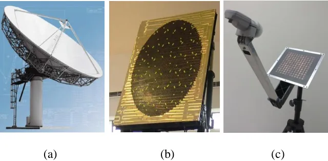
Figure 1. 1. (a) Parabolic antenna (b) Phased array antenna (c) reflectarray antenna ... 2
Figure 1. 2. Geometry of reflectarray antenna ... 5
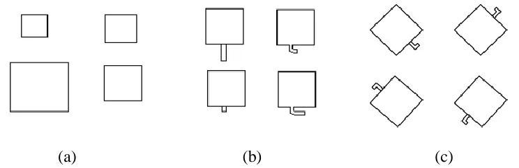
Figure 1. 3. (a) Variable size patches (b) Identical patches with phase delay line (c) Identical planar elements with variable angular rotation ... 5
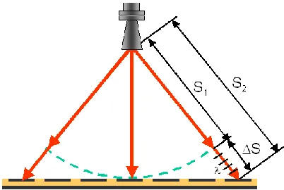
Figure 1. 4. Differential spatial phase delay of reflectarray ... 8
Figure 2. 2. Stub-loaded reflectarray cell element ... 15
Figure 2. 1. Reflectarray configuration ... 15
Figure 2. 3. Reflectarray with variable size patch elements (Huang & Encinar 2007) ... 16
Figure 2. 4. Total electric field for a unit cell resonant element reflectarray ... 17
Figure 2. 5. Extended unit cells for (a) non-edge elements (b) corner elements the element under consideration is the central element indicated by the dashed lines (Zhou et al. 2011) ... 19
Figure 2. 6. Unit cell reflectarray resonant element (Ismail & Kiyani 2013) ... 20
Figure 2. 7. Reflection loss curve at 10GHz ... 21
Figure 2. 8. Dielectric absorption in the substrate region of reflectarray (Ismail & Kiyani 2014) ... 22
Figure 2. 9. Reflection phase curve at 10GHz ... 23
Figure 2. 10. Proposed phase shifter cell (a) expended view (b) top view for symmetric case (c) top view for asymmetric case (d) top view for a u-shaped delay line (Carrasco et al. 2007) ... 25
Figure 2. 11. (a) Stacked layers illuminated by feed (b) multi-layer reflectarray (Encinar 2001), (Encinar & Zornoza 2003) ... 26
Figure 2. 13. Periodic cell of reflectarray split ring elements
(Misran et al. 2003) ... 27
Figure 2. 14. Four FSS rings are rendered per each cell element of the reflectarray. ... 29
Figure 2. 15. (a) reflectarray cell elements (b) FSS ring cell (Shaker et al. 2008)... 29
Figure 2. 16. (a) Crossed-dipole array on the top of designed reflectarray (b) square-loop FSS on the bottom of the designed reflectarray (Li et al. 2011) ... 30
Figure 3. 1. Phases of the research work ... 31
Figure 3. 2. Detailed flow of the research work ... 32
Figure 4. 1. (a) Top view of symmetric case (b) Built unit cell model ... 38
Figure 4. 2. Reflection loss curve at 10.40GHz ... 39
Figure 4. 3. Phase as a function of line length for an aperture length of 9.17mm at 10.40GHz... 40
Figure 4. 4. Amplitude as a function of line length for an aperture length of 9.17mm at 10.40GHz ... 41
Figure 4. 5. Phase and amplitude curve comparison ... 41
Figure 4. 6. Phase curves at different line length values... 42
Figure 4. 7. Phase comparison with and without ground plane at 10.40GHz ... 43
Figure 4. 8. Reflection loss comparison with and without ground plane at 10.40GHz .... 43
Figure 4. 9. (a) Geometry of miniaturized FSS (b) Unit cell built model in HFSS... 46
Figure 4. 10. Unit cell geometry of 1st design ... 47
Figure 4. 11. Frequency response of 1st design ... 47
Figure 4. 12. Unit cell geometry of 2nd design ... 49
Figure 4. 13. Frequency response of 2nd design ... 49
Figure 4. 14. Unit cell geometry of 3rd design ... 51
Figure 4. 15. Frequency response of 3rd design ... 51
Figure 4. 16. Built model of reflectarray in CST... 54
Figure 4. 17. Low loss materials... 56
Figure 4. 18. High loss materials ... 56
Figure 4. 19. Reflection phase curves for different substrate materials ... 58
Figure 4. 21. Reflection loss curves with variable substrate thickness ... 61
Figure 4. 22. Effects of substrate thickness on reflection loss ... 62
Figure 4. 23. Reflection phase curve with variable substrate thicknesses ... 63
Figure 4. 24. Reflectarray configuration schematics (a) rectangular patch with largest reflection area (b) triangular loop with smallest reflection area ... 66
Figure 4. 25. Surface current density on reflectarray resonant elements (a) rectangular patch (b) square patch (c) triangular patch (d) dipole (e) square loop (f) triangular loop ... 68
Figure 4. 26. Reflection loss curve of each resonant element ... 69
Figure 4. 27. Reflection phase curve of each resonant element ... 70
Figure 4. 28. Effect of area of resonant element on surface current density and reflection loss performance ... 71
Figure 4.29. Relationship between bandwidth and static phase range with variation in surface current density ... 72
Figure 4. 30. Predicted and formulated reflection phase curves for rectangular patch, square patch and triangular patch ... 74
Figure 4. 31. Predicted and formulated reflection phase curves for dipole, square loop and triangular loop ... 74
Figure 4. 32. FSS-RA design configuration with dipole, square loop and triangular loop (units in mm) ... 76
Figure 4. 33. Computer built models (a) CST MWS (b) Ansoft HFSS ... 77
Figure 4. 34. Reflection and transmission for (a) dipole (b) square loop (c) triangular loop ... 79
Figure 4. 35. Stacked layer reflectarray configuration ... 81
Figure 4. 36. Reflection loss curves for various loop length variations ... 83
Figure 4. 37. Reflection phase curves for various loop length variations ... 84
Figure 4. 38. Surface current distributions for loop length variation of 5.2mm and 6.8mm ... 84
Figure 5. 1. Fabricated rectangular X-band waveguide simulator ... 89
Figure 5. 2. Fabricated two patch unit cell elements ... 90
Figure 5. 3. Dimensions measurements using digital vernier caliper ... 90
Figure 5. 5. Simulated and measured reflection loss on 0.508mm thick substrate (a) rectangular patch, square patch and triangular patch (b) dipole, square
loop and triangular loop ... 94 Figure 5. 6. Simulated and measured reflection phase for 0.508mm thick substrate
(a) rectangular patch, square patch and triangular patch (b) dipole, square loop and triangular loop ... 96 Figure 5. 7. Scattering parameter measurement setup
(a) two port wave guides (b) FSS-RA resonant element inserted in
between the aperture of waveguides ... 98 Figure 5. 8. Simulated and measured transmission response for
RESEARCH ACCOMPLISHMENTS (PUBLICATIONS/AWARDS)
Following is the list of publications and awards achieved in result of the research work presented in this thesis.
International Refereed Journals
[1] M. Y. Ismail and Arslan Kiyani, “Characterization of Printed Reflectarray
Elements on Variable Substrate Thicknesses,” International Journal of Electrical, Electronic Science and Engineering, Vol. 8, No. 2, pp. 208-212, 2014.
[2] Arslan Kiyani and M. Y. Ismail, “Design and Analysis of High Performance
Reflectarray Resonant Elements,” Procedia Engineering, Vol. 53, pp. 248-254,
2013.
Proceeding Papers
International Conferences
[3] M. Y. Ismail and Arslan Kiyani, “Characterization of Printed Reflectarray
Elements on Variable Substrate Thicknesses,” International Conference on
Communication and Information Technology (ICCIT 2014), February 2014, Rio de Janerio, Brazil.
[4] M. Y. Ismail and Arslan Kiyani, “Investigation of Reflection Area on Strategic
Reflectarray Resonant Elements,” IEEE International Symposium on Wireless
Technology and Applications (ISWTA 2013), September 2013, Kuching, Malaysia.
[5] Arslan Kiyani and M. Y. Ismail, “Numerical Model for Phase Distribution
Characterization of Reflectarray Elements,” IEEE International Symposium on
Local Conferences
[6] Arslan Kiyani and M. Y. Ismail, “Integrated Reflectarray Antenna with FSS
Resonant Elements for Scan Blindness Reduction,” Malaysian Technical
Universities Conference on Engineering and Technology (MUCET 2013), December 2013, Pahang, Malaysia.
[7] Arslan Kiyani and M. Y. Ismail, “Design and Analysis of High Performance
Reflectarray Resonant Elements,” Malaysian Technical Universities Conference
on Engineering and Technology (MUCET 2012), November 2012, Perlis, Malaysia.
Awards
International Recognition
[1] Semi-Grand Prize (Gold Medal & Special Trophy) awarded by Korean Invention
Promotion Association (KIPA) for the product “Frequency Selective Reflector for
Radio Communications,” at Seoul International Invention Fair (SIIF 2013),
November 2013, South Korea.
[2] Gold Medal for the product “Frequency Selective Reflector for Radio
Communications,” under Telecommunications category at 24th International
Invention, Innovation and Technology Exhibition (ITEX 2013), May 2013, KLCC, Malaysia.
Local Recognition
[3] Gold Medal for the product “Frequency Selective Reflector for Radio
Communications,” under Electrical, Electronics and Communications category at
Research and Innovation Festival (R&I 2012), November 2012, UTHM, Malaysia.
Patents
[1] M. Y. Ismail and Arslan Kiyani, “Frequency Selective Reflector for Radio
Communications,” applied for Patent Filing with Application Number
CHAPTER 1
INTRODUCTION AND BACKGROUND
(a) (b) (c)
The design requirements of spacecraft antennas for satellite communications and telecommunication missions are becoming extremely stringent. A variety of military systems employ multiple antenna apertures on a single platform such as a ship or an aircraft. In order to reduce cost and improve performance characteristics, it is desirable to combine multiple functions into a single aperture. Wide bandwidth, low cost and light weight reflectarrays with frequency selectivity properties are needed to accomplish this goal. As a consequence, another field of interest is the integration of reflectarrays with Frequency Selective Surfaces (FSSs). FSSs compromise of an array of periodically arranged patches or apertures on a dielectric substrate. They provide different
characteristics over different frequency bands hence regarded as filters of
electromagnetic waves. The frequency selective properties can be exploited to make a reflectarray antenna much more efficient. The design of such array responds to the more and more demanding requirements on modern antenna arrays with purpose of improving antenna performance such as widening of scan region (increased phase range) for the reduction of scan blindness.
[image:16.612.166.486.71.228.2]X and Ku frequency bands have been targeted for the operation of proposed reflectarray configurations. X-band is most often used in modern radars applications. X-band radar frequency sub-bands are used in civil, military, and government institutions for weather monitoring, air traffic control, maritime vessel traffic control, defense tracking, and vehicle speed detection for law enforcement. Whereas, Ku-band is primarily used for satellite communications, most notably for fixed and broadcast
services, and for specific applications such as NASA's Tracking Data Relay Satellite
used for both space shuttle and International Space Station (ISS) communications.
1.1. Problem statement
Despite significant advantages of reflectarrays such as flat structure, low profile and high gain, the major shortcoming of most of the printed reflectarrays is their narrow band operation and limited phase range. One of the main shortfalls of the conventional reflectarrays is that they have no ability of providing constant paths for the ray from feed to the aperture plane, known as progressive phase distribution. Thus there is a difficulty to convert spherical wave generated by the feed into a plane wave resulting in phase errors. Moreover, scan blindness is one of the known effects resulting due to the limited phase range. It degrades the reflectivity performance, limits the scan range and lowers the antenna efficiency. It is an undesirable feature which results in a decrease in gain at some specific frequencies causing antenna array to stop function. In this regard a complete understanding of this phenomenon and an accurate method for the prognosis of scan blindness is of great practical interest.
1.2. Objectives of the research work
This research provides a comprehensive analysis for the performance optimization of reflectarrays. The key objectives of this research work are as follow:
1. To investigate X-band (8-12GHz) reflectarray antenna by employing strategic
resonant elements.
2. To design Frequency Selective Reflectarrays (FSS-RA) in order to achieve an
increased static phase range for the optimization of scan blindness.
3. To demonstrate the functionality of the predicted reflectarrays with optimized
1.3. Scopes of the research work
This research work focuses on the study of various factors that can affect the performance of reflectarray antennas within the X-band and Ku-band frequency range. Theory of operation including the variable substrate thickness, material properties and different resonant element configurations has been investigated thoroughly. In this work the feasibility of reflectarray antenna integrating with FSS has been investigated. Moreover, the FSS reflectarray configurations have also been shown for performance improvement in both X-band and Ku-Band. Analytical investigations and numerical characterization of designed reflectarray antennas were carried out using commercially available computer models of CST Microwave Studio, Ansoft HFSS and MATLAB. Scattering parameter measurements using waveguide simulator technique have also been carried out in order to validate the theoretical analysis by comparing the simulated and measured results.
1.4. Operation principle of reflectarray antenna
Figure 1. 2. Geometry of reflectarray antenna
Various techniques including identical patches of variable-length stub (Javor et al. 1995), square patches of variable size (Pozar & Metzler 1993) and identical planar elements of variable rotation angle (Huang & Pogorzelski 1998) have been reported for the phasing of reflectarray elements as given in Figure 1.3.
(a) (b) (c)
Figure 1. 3. (a) Variable size patches (b) Identical patches with phase delay line (c) Identical planar elements with variable angular rotation
[image:19.612.146.518.427.548.2]1.5. Advantages of reflectarray antenna
Reflectarray antenna offers the best characteristics and eliminates the poor features of parabolic reflector and phased array antennas. Several advantages of reflectarray antennas are discussed by (Huang 1995), (Bialkowski & Encinar 2007), (Encinar 2008) as below:
1. The reflectarray antenna can achieve more than 50% in terms of antenna
efficiency because power divider is no longer necessary. This fact can be accepted for very large apertures as very little resistive insertion loss has been detected.
2. For the wide-angle beam scanning capabilities, similar to phased-array antenna,
the reflectarray meet the specification which the main beam can tilt at a large angle, more than 50° from its broadside direction. Therefore, the complicated high-loss beam-forming network and high-cost transmit/receive amplifier modules is not necessary anymore.
3. Under certain circumstances, especially in the situations where a large aperture
spacecraft antenna needed a deployment mechanism, the physical structure of the reflectarray provide a simpler easy handling folding mechanism compared to the parabolic antenna.
4. The flat structure of the reflectarray is convenient when mounting the new
antenna to the existing one without adding extra weight or volume to the overall structure.
5. It can be easily fabricated with a simple and low-cost chemical etching process
6. With a large number of radiating elements being used on the reflectarray
surface, the antenna is capable for elemental phase adjustment. Consequently, it can achieve very precisely contour beam shape based on the phase synthesis.
7. By locating multiple feed elements at the focal area of the antenna, it can
achieve multiple-beam of the antenna radiation pattern.
8. Reflectarrays have demonstrated their capability to produce fixed focused and
contoured beams, using simple photo-etching techniques. Reconfigurable-beam reflectarrays have been developed by introducing control devices on the reflecting elements; also some potential applications of reflectarrays in space have been researched such as contoured beam antennas for Direct Broadcast Satellites (DBS) and very large inflatable antennas.
1.6. Disadvantages of reflectarray antenna
Despite all the advantages mentioned above, the major shortcoming of most of the
printed reflectarrays is their narrow-band operation and scan blindness (Li et al. 2011).
1.6.1 Bandwidth performance
The bandwidth performance of reflectarray antenna can be limited by four factors which are as follows (Huang 1995):
Microstrip patch element
Array element spacing
Feed Antenna bandwidth
Microstrip patch element can generally achieve a bandwidth of only 3% because of its thin cavity. Techniques such as stacked dual patch or the patch with a thicker substrate can be employed for the bandwidth enhancement. The array element spacing factor limits the performance of reflectarray antenna depending upon the frequency. Therefore an optimum value is required in order to avoid the grating lobes and mutual coupling effects. It has been reported that element spacing effect will not be detrimental until the frequency variation is more than 30% (Huang 1995). Third factor affecting the bandwidth of reflectarray antenna is the feed antenna which can be designed to operate over a bandwidth of at least 10% while maintaining a relatively constant beam shape and input impedance. Cavity-backed dipoles and waveguide horns are the possible candidates to be used as feed antennas (Huang 1995).
[image:22.612.228.429.479.614.2]The fourth important factor that limits the reflectarray bandwidth is the spatial phase delay (ΔS) which is described as the difference between the electrical paths of the two elements in the array. It can be seen from Figure 1 .4 ΔS, is the difference between the electrical paths S1 and S2. This will be maximum when the delay is calculated comparing the element in the centre of the array to the one at the edge. This ΔS can be many multiples of the wavelengths at the center operating frequency and cause phase errors (Huang 1995). Spatial phase delay needs to be minimized by obtaining a planar wavefront in order to reduce the phase errors.
1.6.2 Phase error compensation considerations
The main shortfall of reflectarrays is that they have no ability of providing constant paths for the ray from feed to the aperture plane, which is inherently offered by a parabolic reflector. Thus there is a difficulty to convert spherical wave generated by the feed into a plane wave resulting in phase errors that reduce its gain as the frequency departs from the resonant frequency. For typical reflectarrays being of many
wavelengths in size, the required phase shift can be many multiples of 360◦. The actual
value depends upon the focal length and diameter in terms of wavelength (Sayidmarie & Bialkowski 2008). In order to counter this problem more recent approaches involve the use of different resonant size elements such as concentric rings, double square rings, double cross loops or more advance shapes such as windmill, compound cross loop or double-petal loop (Misran et al. 2010), (Chaharmir et al. 2006), (Hua Li et al. 2007), (Ren et al. 2011). The use of such elements provides not only the phase range of greater than 360°.
1.6.3 Scan blindness
1.7. Frequency Selective Surfaces (FSSs)
A Frequency Selective Surface (FSS) is an array of periodically arranged patches or apertures on a dielectric substrate that provide different characteristics over different frequency bands regarded as filters of electromagnetic waves. Such structure shows total reflection or transmission in the resonance region. Frequency behavior of an FSS is entirely determined by the geometry of the surface in one period i.e. unit cell (Munk 2000). FSSs found many application areas such as antenna radomes, antenna polarizers, dichroic reflectors, artificial magnetic conductors and waveguide or cavity controlled coupling (Yan et al. 2014), (Bayatpur & Sarabandi 2008).
1.8. Reflectarray integration with FSS
FSS's can be used to shape the frequency or angular response of an antenna. The integration of reflectarray antennas with FSS is convenient from the structural point of view, since it results in a more compact configuration and in performance enhancement. Another advantage is that the FSS can be used as an Electronic Band Gap material, to enlarge the bandwidth of printed array antennas (Erdemli et al. 2002). FSS-Baked reflectarray structure is different from a conventional reflectarray as it implements FSS elements for the backing of reflectarray structure. FSS layer provides a good isolation between the reflectarray elements of different bands. Second there is more freedom for the selection of the element type compared to conventional methods. Experimental investigations on arrays of elements of different shapes like Jerusalem cross, circular ring and the square loop have been carried out by (Munk 2000).
intuitively deduce that a smaller periodicity in a periodic array leads to less variability
in the induced electric current distribution, which in turn results in a reflectivity response less sensitivity to the overall dimensions.
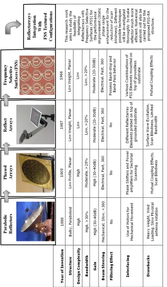
1.9. Progress towards FSS planar reflector antennas
F
ig
u
re
1
.5
.
P
ro
g
re
ss
t
o
w
ar
d
s
F
S
S
r
ef
le
ct
o
r
an
te
n
n
[image:26.612.158.492.103.676.2]1.10. Flow of thesis
Chapter 1 explains the basic introduction and background on the evolution of reflectarrays from conventional parabolic reflectors and phased array antennas. It provides the operation principle of reflectarrays and its various advantages and limitations. This chapter also explains the means for the integration of reflectarrays with FSS configurations for the performance improvement.
Chapter 2 presents the detailed theoretical overview of reflectarrays and FSS along with the implementation of critical design configurations that have been used in the past by the renowned researchers and experts. It thoroughly elaborates the reflectarray analysis techniques and various performance parameters required to analyze the reflectivity of reflectarrays.
Chapter 3 provides a brief outline of the research methodology by explaining the different phases and flow that have been opted during the whole research work. It also provides a comparison of commercially available computer models of CST Microwave Studio and Ansoft HFSS that have been rigorously utilized for the analysis of infinite reflectarrays and FSS-RA.
Chapter 4 starts with the validation work of multilayer reflectarrays by using CST microwave Studio and miniaturized FSS by utilizing Ansoft HFSS. After finalizing the settings of both the computer simulation tools, infinite array model has been designed to investigate the different factors affecting the reflectarray performance. Moreover, the detailed analysis of strategic reflectarray resonant elements, FSS-RA's and stacked layer is presented respectively.
In Chapter 5, the fabrication of unit cell reflectarrays, dimension measurements using digital vernier caliper and complete measurement setup for the scattering parameter measurements is presented. It also provides the comparison of simulated and measured results by incorporating the fabrication discrepancies.
CHAPTER 2
THEORETICAL BACKGROUND AND LITREATURE REVIEW
Literature study is one of the most crucial parts of the research work. Reliable sources of related research papers and books by renowned researchers have been utilized in order to thoroughly understand the basic fundamentals of the reflectarrays. A detailed background of reflectarray antennas is presented in accordance with the limitations mentioned in the Section 1.6. This chapter further elaborates various analysis techniques, number of critical configurations and advance investigations being carried out by different researchers for the performance improvement of reflectarrays.
2.1. Reflectarray cell element configurations
Reflectarrays are “quasi-periodic” structures composed of different cell elements that
are mounted on top of a flat dielectric substrate as shown in Figure 2.1, where F is the
feed horn antenna, his the height of the dielectric substrate, Gis the ground plane at the
bottom of the substrate, Oand Aare the incident fields and routis the reflected field. A
As the length of patch is parallel with the polarization of incident wave, hence phase is realized by changing the length of the resonating patch while keeping the width
constant. The φpatch of the field reflected from a rectangular patch in the reflectarray be
chosen so that the total phase delay from the feed to the fixed aperture plane in front of the reflectarray is constant for all elements. Required phase (φpatch) that ought to be
contributed by the patch can be calculated by using equation 2.1. The notation for the equation given below is defined in Figure 2.1.
[image:29.612.209.517.72.253.2]𝑲𝒐 𝑭𝑨 − 𝑭𝑶. 𝒓𝒐𝒖𝒕 − 𝝋𝒑𝒂𝒕𝒄𝒉= 2πN (2.1)
[image:29.612.218.435.423.605.2]Figure 2. 2. Stub-loaded reflectarray cell element Figure 2. 1. Reflectarray configuration Feed Horn
Resonant element Substrate
However stub-loaded patch element demonstrated the generation of spurious radiations which can alter the required phase and degrade the cross-polarization level. Rectangular patch is the most common type of cell element that has been used widely in some
previous literatures by (Pozar et al. 1997), (Leberer & Menzel 2005). Pozar presented
microstrip patch elements of variable size and also discussed that polarization selectivity can be achieved by using rectangular patches for linear polarization, and
square patches, circular patches or cross dipoles for dual/circular polarization (Pozar et
al. 1997). Reflectarray with variable size patches have been implemented to address the
[image:30.612.202.457.283.414.2]issues related with stub-loaded patches as shown in Figure 2.3 (Huang & Encinar 2007).
Figure 2. 3. Reflectarray with variable size patch elements (Huang & Encinar 2007)
2.2. Reflectarray analysis techniques
2.2.1 Full wave analysis
[image:31.612.124.520.326.556.2]A full-wave analysis technique such as Method of Moment (MoM), Finite Integral Method (FIM) and Finite Element (FEM) must be utilized to compute the losses and phase-shift produced by the reflected field of each element. Usually, in reflectarrays mutual coupling can degrade the reflectivity performance thus it cannot be neglected especially in the case of varying-sized patches. In varying-sized patch reflectarray the dimensions of some of the patches are larger than half-wavelength (0.5λ) in the dielectric and the separation between the patches is usually small (less than 0.25λ). Therefore, the effect of mutual coupling can be stronger in this case. (Huang & Encinar 2007) summarized some of the important considerations that are generally needed to be taken into account for analyzing reflectarray antenna using full-wave analysis method.
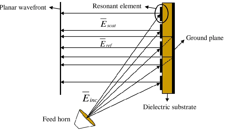
Figure 2. 4. Total electric field for a unit cell resonant element reflectarray
When the electric field impinges on the resonant elements from a feed horn, some of the incident energy is reradiated by the resonant patches and remaining is reflected by the ground plane as shown in the above Figure 2.4. Therefore the total electric field can be given by equation 2.2 as:
E
tot
E
inc
E
ref
E
scat (2.2) Ground plane Resonant elementDielectric substrate Feed horn
Planar wavefront
inc
E
scat
E
ref
2.2.2 Infinite array analysis
The infinite array model can be used in case of reflectarrays having a large number of elements by applying Floquet’s theorem. In this way the analysis is reduced to only one periodic cell. Moreover, this technique provides the good prediction of each individual element of the array by automatically taking into account the mutual coupling effect. Any type of phase shifter element can be analyzed by using infinite array approach. For elements with stub of different length (attached or aperture-coupled), all the radiating patches are exactly the same and only the stub length varies from one element to the next element. In this case, the infinite array approach will be very accurate, because the coupling produced by the stubs is less significant, assuming a minimum of separation between stubs and other metallic lines or patches (Encinar 2008).
For multilayer reflectarrays consisting of aperture-coupled patches or stacked patches of variable size, a modular approach based on Spectral-Domain (SMoM) has
been used in a periodical environment as described and used by (Wan & Encinar 1995),
(Gay-Balmaz et al. 2000). Spectral domain Method of Moment is very appropriate and
numerically efficient for full-wave analysis of periodical structures, assuming planar arrays of patches or apertures in a single or multilayer configuration.
2.2.3 Local periodicity (LP) approach
2.2.4 Extended local periodicity (ELP) approach
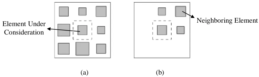
Reflectarrays are inherently aperiodic due to the need to compensate the spatial phase delay from the feed. Therefore an infinite approach where periodicity is applied on an extended unit cell, which includes the actual surrounding elements is proposed by
(Zhou et al. 2011). This technique is known as the Extended Local Periodicity (ELP)
approach. Each cell is increased to include the nearest eight surrounding elements in a rectangular grid. Whereas, for the non-edge elements the extended unit cell consists of nine elements with the element under consideration as the central one as shown in Figure 2.5. The surrounding elements are the actual neighboring elements in the reflectarray.
[image:33.612.121.558.312.443.2](a) (b)
Figure 2. 5. Extended unit cells for (a) non-edge elements (b) corner elements the element under consideration is the central element indicated by the dashed lines
(Zhou et al. 2011)
It can be concluded that among all the techniques mentioned above, full wave and infinite array analysis technique are commonly used. Full wave modeling of reflectarrays plays an important role by taking into account all the physical aspects of interests such as finiteness of radiating patch elements on top of the dielectric substrate, mutual coupling effect among the patch elements, estimation of surface currents and also complex multilayered structures. Whereas infinite array analysis is the best basis for the design of a very large finite array and the inter-element spacing can be kept constant for the ease of the design.
Neighboring Element Element Under
2.3. Performance parameters of reflectarray
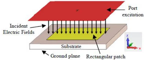
[image:34.612.185.475.332.453.2]One of the most important aspects of the reflectarray design and analysis is the accurate characterization of the resonant element. Once the unit cell has been fully characterized, the performance of reflectarray antenna can be carried out on the basis of reflection loss, 10% bandwidth, reflection phase and Figure of Merit (FoM). A reflectarray unit cell has been shown in the Figure 2.6. It can be seen that the port excitation (feed) is impinging the electric fields on the reflectarray resonant element. Some of the incident microwave energy is being absorbed in the substrate region and remaining is reflected back with a particular phase depending on the design of the resonant element. This reflected field consists of scattered energy from the resonant element and the reflected energy from the ground plane.
Figure 2. 6. Unit cell reflectarray resonant element (Ismail & Kiyani 2013)
2.3.1 Reflection loss and 10% bandwidth
Figure 2. 7. Reflection loss curve at 10GHz
The bandwidth of the reflectarray antenna can be represented by the reflection loss curve. In order to analyze the bandwidth performance, the ratio of the bandwidth is defined by moving 10% above the maximum reflection loss value at the resonance. Reflectarrays attribute dielectric loss due to the dielectric absorption in the substrate and conductor losses due to the conductivity of the conducting material utilized for the
design of reflectarray resonant elements (Pozar et al. 1997), (Ismail & Inam 2010). The
dielectric loss occurs due to the strong electric fields in the substrate region and copper loss occurs due to high current generated on the top surface of the patch element. The incident electric field generates electric current densities (J) on the conducting surfaces of the resonating elements. These fields are maximum at the resonant frequency. This is because at resonant frequency the reflectivity of reflectarrays is at its maximum level, which is the reason of the highest loss at the resonant frequency (Kiyani & Ismail 2012). Thus the reflection loss performance of the reflectarrays depends on the material properties and thickness of the dielectric substrate. The reflection loss can be given by equation 2.3 as:
where, RL is the reflection loss and αdand αc are the attenuation due to the dielectric
substrate and conductor loss respectively which can be calculated using equations 2.4 and 2.5 as:
( ) tan
2
d r
(2.4) 8.68 ( ) 2 c m c db cm WZ
(2.5)Where ω is the angular frequency, µo is the permeability of free space, εo is the
permittivity of free space, εr is the relative permittivity, Zm is the input impedance and ζc
is the conductivity. Moreover, the dielectric absorption into the substrate region of reflectarray antenna is depicted in Figure 2.8. It can be seen that the port excitation is placed at a distance of λg/4 to incident the electric fields on the reflectarray resonant
element and the dielectric substrate t, whereλg is the guided wavelength. These incident
[image:36.612.205.454.520.672.2]fields are being absorbed by the substrate region resulting in multiple bounces phenomenon. Thus the intensity of dielectric absorption in a particular substrate determines the reflection loss performance. For thinner substrates, a number of rapid multiple bounces will occur due to higher dielectric absorption which contributes the higher reflection loss performance. Whereas, the number of multiple bounces can be decreased in order to obtain low reflection loss performance by increasing the substrate thickness.
2.3.2 Reflection phase and Figure of Merit (FoM)
Reflection phase is another important parameter that is used to analyze the reflectivity and bandwidth of reflectarrays. Moreover phase errors can also be observed using phase plots. Figure 2.9 shows the S-shaped reflection phase curve for the reflectarray antenna resonating at 10GHz. For the minimum amount of phase errors the reflection phase curve of reflectarray should cover the whole 360° phase range keeping the reflection phase to be 180° at resonance, where the maximum reflection of the signals occurs. The bandwidth performance of reflectarray antennas can also be realized by using reflection phase curves. Generally, the bandwidth is calculated based on the slope of the phase curve. Steeper the slope of reflection phase curve, lesser will be the bandwidth. Another factor that can be used to analyze the reflection phase curve is the Figure of Merit (FoM) and the static phase range, which shows the linearity of the phase curve. FoM is defined by (Ismail & Inam 2012) as the ratio of change in reflection phase to the change in the frequency and it can be expressed as:
FoM ( MHz)
f
[image:37.612.147.515.398.685.2] (2.6)
Figure 2. 9. Reflection phase curve at 10GHz
Δ
2.4. Reflectarray bandwidth limitations
The main disadvantage of reflectarray is the limitation on the available bandwidth, which has been taken into account by explaining the three main factors responsible for the reflectarray phasing errors resulting in the gain reduction. Three main factors affecting the reflectarray bandwidth are considered. First factor is the phase compensation requires dealing with the non-equal path lengths from feed to the aperture i.e. conversion of spherical wave front into planar wave front. Ray-tracing approach is used to show that the phase compensation depends upon the position of the element across the array. Second factor is related to the limited phase range of typical microstrip reflectarrays. Truncation of compensation phase is accomplished by subtracting an integer multiple of 2π from the exceeding phase values and final the third factor deals with the phase shift generated by the array elements as a function of frequency (Sayidmarie & Bialkowski 2008). Nonlinear nature of the phase response of the unit cell as a function of the size of its geometrical features restricts the bandwidth of conventional reflectarray antennas to about 4% (Pozar 2003). Thick substrate has been proposed in the past as a method to reduce the slope of the phase response which would in turn broadens the bandwidth. Unfortunately, the smaller attainable phase range in
such cases has an adverse effect on gain and overall radiation efficiency (Pozar et al.
1997).
2.5. Multilayer reflectarray configurations
Multilayer reflectarray structures have been suggested as an alternative to overcome bandwidth limitations of the single layer reflectarrays. Such as, the element bandwidth
is provided to be improved by the appropriate design of phase shifter (Carrasco et al.
REFRENCES
Bayatpur, F. & Sarabandi, K., 2008. Single-Layer High-Order Miniaturized-Element
Frequency-Selective Surfaces. IEEE Transactions on Microwave Theory and
Techniques, 56(4).
Bialkowski, M.E. & Encinar, J. A., 2007. Reflectarrays: Potentials and Challenges.
2007 International Conference on Electromagnetics in Advanced Applications, pp.1050–1053.
Carrasco, E., Barba, M. & Encinar, J.A., 2007. Reflectarray Element Based on
Aperture-Coupled Patches With Slots and Lines of Variable Length. IEEE
Transactions on Antennas and Propagation, 55(3).
Chaharmir, M.R., Shaker, J. & Legay, H., 2009. Broadband Design of a Single Layer
Large Reflectarray Using Multi Cross Loop Elements. IEEE Transactions on
Antennas and Propagation, 57(10).
Chaharmir, M. R, Shaker, J, Cuhaci, M. and Ittipiboon, A., 2006. Antenna With Double Square Rings. , 48(7), pp.1317–1320.
Debatosh Guha (Institute of Radio Physics and Electronics, University of Calcutta,
India), Yahia M.M. Antar (Royal Military College, C., 2011. Microstrip and
Printed Antennas - New Trends , Techniques and Applications, John Wiley & Sons, Ltd.
Encinar, J.A., 2008. Analysis , Design and Applications of Reflectarrays. , (October), pp.22–24.
Encinar, J.A. et al., 2006. Design of a 1-metre reflectarray for DBS application with
15% bandwidth. 2006 First European Conference on Antennas and Propagation.
Encinar, J.A., 2001. Design of two-layer printed reflectarrays using patches of variable
size. IEEE Transactions on Antennas and Propagation, 49(10).
Encinar, J.A., 2010. Recent advances in reflectarray antennas. Antennas and
Encinar, J.A. & Zornoza, J.A., 2003. Broadband design of three-layer printed
reflectarrays. IEEE Transactions on Antennas and Propagation, 51(7).
Erdemli, Y.E. et al., 2002. Frequency-selective surfaces to enhance performance of
broad-band reconfigurable arrays. IEEE Transactions on Antennas and
Propagation, 50(12).
Gay-Balmaz, P., Encinar, J. a. & Mosig, J.R., 2000. Analysis of multilayer printed
arrays by a modular approach based on the generalized scattering matrix. IEEE
Transactions on Antennas and Propagation, 48(1), pp.26–34.
Gianvittorio, J.P. et al., 2003. Self-similar prefractal frequency selective surfaces for
multiband and dual-polarized applications. IEEE Transactions on Antennas and
Propagation, 51(11).
Hannan, P. & Balfour, M., 1965. Simulation of a phased-array antenna in waveguide.
IEEE Transactions on Antennas and Propagation, 13(3).
Hua Li, B.-Z.W. and P. Du, 2007. Novel broadband reflectarray antenna with
windmill-shaped elements for millimeter-wave application. International Journal of Infrared
and Millimeter Waves, 28(5), pp.339–344.
Huang & Encinar, 2007. Overview of Analysis Techniques in Reflectarray Antennas,
Wiley Inter Science.
Huang, J. & Pogorzelski, R.J., 1998. A Ka-band microstrip reflectarray with elements
having variable rotation angles. IEEE Transactions on Antennas and Propagation,
46(5).
Huang, J., 1995. Analysis of a Microstrip Reflectarray Antenna for Microspacecraft
Applications., Report, pp.153–173.
Ismail, M.Y. et al., 2010. Reflectivity of Reflectarrays Based on Dielectric Substrates Radio Communications and Antenna Design Laboratory , Department of Communication Engineering , Faculty of Electrical and Electronics Engineering , Department of Mechanical Engineering , Faculty . , 3(1), pp.180–185.
Ismail, M.Y. & Inam, M., 2012. Resonant Elements for Tunable Reflectarray Antenna
Design. International Journal of Antennas and Propagation, 2012, pp.1–6.
Ismail, M.Y. & Kiyani, A., 2014. Characterization of Printed Reflectarray Elements on
Variable Substrate Thicknesses. International Journal of Electrical, Electronic
Ismail, M.Y. & Kiyani, A., 2013. Investigation of reflection area on strategic
reflectarray resonant elements. 2013 IEEE Symposium on Wireless Technology &
Applications (ISWTA), 1, pp.363–367.
Javor, R.D. & Chang, K., 1994. Offset-fed microstrip reflectarray antenna - Electronics
Letters. , 30(77), pp.1593–1594.
Javor, R.D., Wu, X.-D.W.X.-D. & Chang, K.C.K., 1995. Design and performance of a
microstrip reflectarray antenna. IEEE Transactions on Antennas and Propagation,
43(9).
Kiyani, A. & Ismail, M.Y., 2012. Numerical model for phase distribution
characterization of reflectarray elements. 2012 International Symposium on
Telecommunication Technologies, pp.160–163.
L.-S. Ren, Y.-C. Jiao, F. Li, J.-J. Zhao, and G.Z., 2011. A Novel Double-Petal Loop
Element for Broadband Reflectarray. Progress In Electromagnetics Research
Letters, 20(January), pp.157–163.
Leberer, R. & Menzel, W., 2005. A dual planar reflectarray with synthesized phase and
amplitude distribution. IEEE Transactions on Antennas and Propagation, 53(11).
Li, L. et al., 2011. Frequency Selective Reflectarray Using Crossed-Dipole Elements
With Square Loops for Wireless Communication Applications. IEEE Transactions
on Antennas and Propagation, 59(1), pp.89–99.
Misran, N., Cahill, R. & Fusco, F., 2003. Concentric split ring element for dual
frequency reflectarray antennas. , Electronics Letters, 39(25), pp.11–12.
Misran, N., Cahill, R. & Fusco, V.F., 2003. Design optimisation of ring elements for
broadband reflectarray antennas., IEEE Microwaves and Antenna Propagation,
150(6), pp.6–10.
Misran, N., Ismail, M.Y. & Islam, M.T., Reflectarray Antenna with Radar
Cross-Section Reduction., International Journal of Integrated Engineering, (1),
pp.17–28.
Munk, B.A., 2000. Frequency Selective Surfaces: Theory and Design,
Wiley-Interscience.
Pozar, D.M., 2003. Bandwidth of reflectarrays. Electronics Letters, 39(21), p.1490.
Pozar, D.M. & Metzler, T.A., 1993. Analysis of a reflectarray antenna using microstrip
Pozar, D.M., Targonski, S.D. & Syrigos, H.D., 1997. Design of millimeter wave
microstrip reflectarrays. IEEE Transactions on Antennas and Propagation, 45(2).
Sayidmarie, K.H. & Bialkowski, M.E., 2008. Investigation into Bandwidth Limitations
of Microstrip Reflectarrays. 2008 3rd International Conference on Information
and Communication Technologies: From Theory to Applications.
Shaker, J., Chaharmir, R. & Legay, H., 2008. Investigation of FSS-Backed Reflectarray
Using Different Classes of Cell Elements. IEEE Transactions on Antennas and
Propagation, 56(12).
Wan & Encinar, J.A., 1995. Efficient computation of generalized scattering matrix for
analyzing multilayered periodic structures. IEEE Transactions on Antennas and
Propagation, 43(11), pp.1233–1242.
Zhou, M. et al., 2011. Analysis of printed reflectarrays using extended local periodicity.
Proceedings of the 5th European Conference on Antennas and Propagation