N A N O E X P R E S S
Open Access
Electrical Properties of Composite Materials
with Electric Field-Assisted Alignment of
Nanocarbon Fillers
Olena Yakovenko
*, Ludmila Matzui, Ganna Danylova, Victor Zadorozhnii, Ludmila Vovchenko, Yulia Perets
and Oleksandra Lazarenko
Abstract
The article reports about electric field-induced alignment of the carbon nanoparticles embedded in epoxy matrix. Optical microscopy was performed to consider the effect of the electric field magnitude and configuration, filler morphology, and aspect ratio on alignment process. Characteristic time of aligned network formation was compared with modeling predictions. Carbon nanotube and graphite nanoplatelet rotation time was estimated using an analytical model based on effective medium approach. Different depolarization factor was applied according to the geometries of the particle and electric field.
Solid nanocomposites were fabricated by using AC electric field. We have investigated concentration dependence of electrical conductivity of graphite nanoplatelets/epoxy composites using two-probe technique. It was established that the electrical properties of composites with random and aligned filler distribution are differ by conductivity value at certain filler content and distinguish by a form of concentration dependence of conductivity for fillers with different morphology. These differences were explained in terms of the dynamic percolation and formation of various conductive networks: chained in case of graphite nanoplatelets and crossed framework in case of carbon nanotubes filler.
Keywords:Composites, Carbon nanotubes, Graphite nanoplatelets, Electric field-induced alignment, Depolarization factor, Electric conductivity, Dynamic percolation
PACS:72.80.Tm82.35.Np81.05.uf81.07.De77.22.Ej87.50.Rr64.60.ah64.60.aq
Background
Tailorable properties provide an application of conductive carbon-based composite materials in many industries as electronic and constructional components: in microelec-tronics, electrostatic dissipation, at electromagnetic shields fabrication, for aircraft structures, etc. [1–4]. They do not corrode like metals but possess appropriate strength, weight, and wide range of conductivity values due to a variety of employed fillers.
Non-spherical particles are more favorable as compos-ite fillers from the perspective of improving electrical conductivity of composite [5–7]. This is due to lower
values of packing factor at increase of particles aspect ratio [8], which is a parameter of statistical percolation model. Therefore, the development of composites with carbon nanotubes (CNTs) and graphite nanoplatelets (GNPs), which are characterized by high values of aspect ratio (101–104) [9], as fillers, is a very promising direc-tion. Besides geometrical anisotropy, CNTs and GNPs distinguish by the anisotropy of physical properties. But at random distribution of filler at composite the anisot-ropy of individual filler particle is compensated. Besides, at random filler distribution, much of it is concentrated in the so-called “blank” branches of a conductive net-work which are disjoint from the overall netnet-work. These losses are particularly considerable at low content of filler in the composite.
* Correspondence:[email protected]
Physics Department, Taras Shevchenko National University of Kyiv, Volodymyrska Str., 64/13, Kyiv 01601, Ukraine
Recomposing of filler and its specific spatial distribu-tion allows obtaining composites with low percoladistribu-tion threshold which reduces the cost of material. The most popular methods of preparation of composites with an-isotropic filler distribution are exposure of liquid com-posite mixture to electromagnetic field and application of mechanical stress. Among disadvantages of filler alignment method by rolling, shearing stress is possible breaking and destruction of carbon nanoparticles under such exposure [10]. Magnetic field-induced alignment requires addition of magnetic components to the com-posite [11]. Thus, electric field-assisted alignment of the filler in composite is the most promising method of anisotropic composite formation from the standpoint of many research groups [12, 13].
But the overwhelming majority of the presented works about electric field-assisted alignment are devoted to carbon nanotubes embedded in polymer matrix [14–18]. The effect of the morphology of the filler particles on the process of alignment is very poorly developed in both theoretical and experimental studies [19–21]. The aim of this study was to investigate the influence of filler morphology on the process of aligned composite forma-tion and to identify and explain differences of concentra-tion dependence of the electrical conductivity of the composites with random and aligned GNP distribution.
Methods
Materials
Based on epoxy resin Larit 285 (Lange Ritter GmbH, Germany), composite materials were fabricated and in-vestigated in this study. In the initial state, this polymer is two-component and consists of liquid epoxy and ap-propriate hardener H 285. Low viscosity of the used resin (600 ÷ 900 mPa × s at 25 °С) and hardener (50 ÷ 100 mPa × s at 25 °С) allows using the impact of an external electric field for the manufacture of composite materials on their basis.
The following materials were used as fillers for the fabricated composite systems:
– Multiwall carbon nanotubes (MWCNTs) (Cheap
Tubes Ins, USA);
– Graphite nanoplatelets (GNPs).
GNPs were obtained by ultrasonic dispersing (in acet-one medium for 3 h) of thermally exfoliated graphite which is a resulting product of deep thermo-chemical treatment of dispersed graphite. The process of GNP manufacturing is described in detail in [22].
Table 1 contains parameters of the used fillers. Their dimensions and shape were estimated by using AFM, SEM, and optical microscopy in papers of our research group [23, 24]. GNP and MWCNT particles distinguish
by shape, size and, therefore, an aspect ratio. Table 1 contents characteristic parameters for the largest, smal-lest, and average particles. The particles are marked “max,” “min,”and“aver”by the values of their aspect ra-tio. Evaluating mass of the particles suggested that dens-ityρ(MWCNT) = 1.8 g/cm3[25],ρ(GNPs) = 2.23 g/cm3, as the density of monocrystalline graphite.
Composite Fabrication
Composite samples that were prepared contained differ-ent concdiffer-entrations of GNPs as a filler (0.05, 0.5, 0.7, 1, 2, 3, 4, 5 wt%). One type of samples had random distribu-tion of the filler, and in another one, GNPs were aligned by external electric field.
Method of composite systems preparation was as follows. At first, required amount of carbon filler was poured into pre-dissolved polymer matrix and mixed mechanically. After that, the mixture was exposed to ultrasonic dispersing for a better distribution of filler in epoxy matrix. Dispersion was carried out in ultra-sonic bath Вaku-9050 with frequency of 40 kHz and maximum output electric power of 50 W. The com-posite mixture was exposed to ultrasonic action for
30 min at 50 W, after that hardener Н 285 was
added to the resulting composite mixture in 100/40 ratio by mass to the weight of Larit 285.
Eventually, for composites with aligned filler distri-bution fabrication, a part of obtained composite mix-ture was poured into plastic mold which was placed between the plates of capacitor. AC voltage with fre-quency of 15 kHz and magnitude of 2000 V was ap-plied to the plates. High-voltage source with the ability to generate AC voltage at 15 kHz frequency and magnitude in the range up to 2000 V or DC voltage with magnitude in the range up to 2000 V was used as a source of electric field. The value of the magnitude of electric field was controlled by uni-versal voltmeter В7-16А.
Under choosing the AC electric field frequency, we kept in mind two points: (1) the frequency should be high enough that the carbon nanoparticles align-ment time would be the time of epoxy hardening; (2) the frequency should be low enough to observe the dynamics of nanoparticles alignment in electric field. Keeping in mind these considerations, we have carried out composites formation at the frequency of 15 kHz.
The other part of the composite mixture was left without the influence of an external electric field.
Optical Microscopy
Investigation of the character of carbon fillers distribution in epoxy matrix under electric field treatment was per-formed for composites with the content of carbon filler of 0.05 wt%. This was done with a stereoscopic optical micro-scope МBS-1 equipped with digital camera Etrek DCM-510. This setup provided the opportunity of observation online of the liquid epoxy with dispersed carbon nanoparti-cles under electric field influence. The configuration of experiment is described in detail in [26, 27]. A series of optical observations of the MWCNTs/− and GNPs/Larit 285 composites was conducted in real time supplying electrodes with AC voltage of 15 kHz or DC voltage and changing the value of electric field magnitude.
Electrical Properties Measurement
Electrical conductivity of the investigated composites was measured by standard two-probe method in DC mode at room temperature with a limit of measurement of elec-trical resistance of 1010ohm. Higher than 1010ohm, resis-tances were measured using teraommetrЕ6–13. Samples for measurements were prepared in the form of regular parallelepipeds with the dimensions 5.0 × 4.0 × 4.0 mm3.
Modeling
Equations by which characteristic time of carbon particle rotation under electric field action was estimated were solved using a mathematical package Maple 13.
Results and Discussion
Optical Observations
The following figures show optical photos of the surface of composite materials GNPs/Larit 285 (Figs. 1 and 2) and MWCNTs/Larit 285 (Figs. 3 and 4) [26] of low filler content (0.05 wt%) at the action of AC electric field.
Processed with AC electric field, composites became more transparent with increasing time of electric field action due to filler movement in the direction of power lines of an external electric field. It was also observed that with increasing time of electric field action, the aligned structures of carbon filler broaden and some clearances emerge between them. This may be due to Van der Waals interactions of carbon nanoparticles. In
this manner, chains of nanocarbon filler of specified dis-tribution are forming in composite.
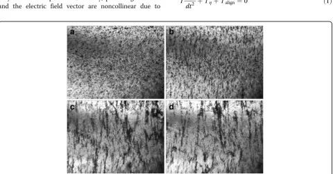
As seen in Fig. 1, for GNPs/Larit 285 composites in em-bedded electrodes configuration, AC electric field action manifests itself in creation of the main conductive path, which closes the supply with external voltage electrodes and leads to a high amplitude current flow through the compos-ite sample. Therefore, alignment of GNPs in Larit 285 was performed by the experimental set when the composite is placed between plates of capacitor. Figure 2 shows that such a configuration of experimental setup in which the current flow through the sample is impossible allows obtaining con-sistently aligned chains of GNPs in polymer matrix.
In case the of MWCNTs/Larit 285 composites treatment with AC electric field, a formation of elongation in the dir-ection of the electric field chains was observed as well. Dis-tinct chains become thicker when time of AC field exposure increases. But characteristic time of aligned chain formation in MWCNTs/epoxy composite is minutes while in GNPs/epoxy composite is seconds in embedded elec-trodes configuration. Moreover, due to GNP shape and size, aligned filler distribution in GNPs/epoxy composites can be formed at less magnitudes of AC electric field than in MWCNTs/epoxy composites. But on the other hand due to GNPs mobility because of its shape and size in compari-son with MWCNTs, the formation of bulk composites with GNP filler is complicated. Aligned network of GNPs tends to destroy shortly after switching off the electric field if the composite has not polymerized completely.
When considering all optical images of aligned net-work under AC electric field formation in GNPs/−and MWCNTs/epoxy composites, we can conclude that under equal conditions when changing only the type of carbon filler, the aligned network is formed faster in the GNPs/epoxy composite. In the case of MWCNTs, their tendency to agglomeration prevents effective alignment in the direction of the applied electric field. It should be noted that DC field is not effective for formation of aligned network in composite [26].
[image:3.595.56.539.99.183.2]To explain the observation by optical microscopy peculiarities of electric field-assisted alignment of the filler of different morphology, a characteristic time of carbon nanoparticle rotation in epoxy matrix under AC electric field action was theoretically estimated.
Table 1Parameters of carbon nanoparticles
Particle sign Shape Length, m Outer radius, m Inner radius, m Thickness, m Aspect ratio Mass, kg
GNPmin Spheroid, Ellipsoid, Disk – 0.2 × 10⁻⁶ – 5 × 10⁻⁹ 80 1.4 × 10⁻¹⁸
GNPmax 30 × 10−6 65 × 10−9 923 4.1 × 10⁻¹⁶
GNPaver 5 × 10⁻⁶ 30 × 10−9 333 5.3 × 10⁻¹⁸
CNTmax Ellipsoid, Cylinder 10 × 10−6 5 × 10⁻⁹ 2 × 10⁻⁹ – 1000 1.19 × 10⁻¹⁸
Modeling of Carbon Particle Alignment in Viscous Medium
The mechanism of composite with a specified spatial distribution of filler formation method is that every car-bon nanoparticle which is embedded in dielectric matrix undergoes polarization under AC electric field action due to the polarization of the interface between the polymer and the particle. Generally, polarizing moment and the electric field vector are noncollinear due to
anisotropy of the nanoparticles. Therefore, when the electric field is activated, a torque which leads to carbon nanoparticle rotation in the direction of the field occurs. It is known that the rotational motion of a particle in this case is described by the following equation [16]:
Id
2Θ
dt2 þTηþTalign¼0 ð1Þ Fig. 1Optical images of electrical“breakdown”formation in 0.05 wt% GNPs/Larit 285 composite under AC electric field action of strength of 36 kV/m, frequency of 15 kHz (embedded electrodes):a—before electric field action;b—after 100 s;c—after 140 s;d—after 160 s of electric field action. Image size 10.8 × 8.0 mm2
[image:4.595.57.539.88.307.2] [image:4.595.59.540.455.706.2]whereIis the moment of inertia of carbon nanoparticle;
Θ is the angle between the particle and the electric field direction; Tη is a damping torque; Talign≈
μ→!E
h i
is field-induced torque; μ→¼fðε;σ1; ;σ2;vÞ
is the polarizing moment which depends on the values of dielectric constant (ε) and conductivity
(σ1,σ2) of nanoparticle and matrix; v=f(m,l,d) is the volume of carbon nanoparticle which depends on its weight (m) and dimensions (l,d).
Generally, polarizing momentμ→ is proportional to the external field E→ and particle’s volume ν and is deter-mined by the formula [28]:
Fig. 3Optical images of 0.05 wt.% MWCNTs/Larit 285 composite under AC electric field action (frequency of 15 kHz, strength of 83.3 kV/ m) (embedded electrodes):a–before electric field action; b–after 12 min;c–after 26 min;d–after 60 min of electric field action. Image size 10,8 × 8,0 mm2[26]
[image:5.595.56.539.87.309.2] [image:5.595.56.541.475.695.2]μ
→¼ε
0εmβν!E
whereε0is the permittivity of free space, εmis a dielec-tric constant of the matrix,βis a dimensionless param-eter which, in particular, depends on the shape of inclusion. In [28], formulas ofβ for an ideal conductive disc and cylinder are given:
βdisk
⊥ ¼σpσ−σm p ; β
disk
II ¼ σp−σm
σm ;
βcylinder
⊥ ¼
2 σp−σm
σpþσm ; β
cylinder
II ¼ σp−σm
σm :
It follows from these dependencies that μ→II≠μ→⊥ (II means codirection of the long axis of the particle and of the field direction,⊥—perpendicularity). Thus, for GNPs and MWCNTs, μ→II>μ→⊥ because of their shape and properties.
To evaluate the characteristic time of carbon particle rotation under electric field action and its alignment by the direction of the field Eq. (1) with the initial condi-tions Θ(t= 0) =Θ0, ddtΘðt¼0Þ ¼0 were solved. Accord-ing to [16], terms in the main equation of movement are as follows:
Tη ¼8πηνdΘ dt ;
Talign¼
1
4νεmReα
½ E2
Sin2Θ;
where
α¼ ε
p−εm
2
= ε
mþ εp−εm
Lx
h i
ε
pþεm
is a
polarizability, εm;p¼εm;p−jσm;p
ω , and εm,p,σm,p are dielectric
constant and conductivity of the medium and particle,
ω= 2πf,f—electric field frequency.
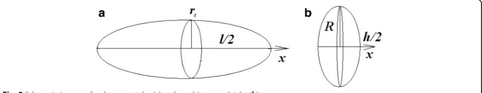
To determine the depolarization factor of carbon nanotube and graphite nanoplatelet, they must be con-sidered as the particles of certain shape (Fig. 5). MWCNT can be considered as ellipsoid only. The
ellip-ticity of the MWCNT in ellipsoid approximation is e
¼ ffiffiffiffiffiffiffiffiffiffiffiffiffiffiffiffiffiffiffiffiffi1−ð2r0=lÞ2
q
. GNP can be considered as spheroid or
as ellipsoid. The ellipticity of the GNP in ellipsoid
ap-proximation is e¼
ffiffiffiffiffiffiffiffiffiffiffiffiffiffiffiffiffiffiffiffiffiffi 1−ðh=2RÞ2 q
and in spheroid
ap-proximation is e¼ð2R=hÞ
ffiffiffiffiffiffiffiffiffiffiffiffiffiffiffiffiffiffiffiffiffiffi 1−ðh=2RÞ2 q
. Then
expressions of depolarization factor take the following form [28].
For the ellipsoid:
Lx¼
1−e2
e3 ðArth e−eÞ:
For the spheroid:
Lx¼
1þe2
e3 ðe−arctan eÞ; Lxþ2LR¼1:
In the above equations, Lx is a depolarization factor if the external field is applied along the x-axis (as in Fig. 5),LRis a depolarization factor if the external field is ap-plied along the radius of GNP.
Expending the depolarization factors in series, the above expressions take the following form.
For the ellipsoidal MWCNT:
Lx¼
4r2 0
l2 ln l r0 −
1
ð2Þ
For the ellipsoidal GNP:
Lx¼ h
2
4R2 ln 4R
h −1
ð3Þ
For spherical GNP:
Lx≈1−
h8πR2−16hRþ3πh2
32R3 ð4Þ
LR≈h
8πR2−16hRþ3πh2
64R3 ð5Þ
In addition, to highlight the peculiarities of particles morphology, CNT volume was asked as the volume of a hollow cylinder ν¼πl r2
0−r2i
, while GNP volume was asked as the volume of a diskν=πR2h.
Carbon nanotube moment of inertia was taken as I ¼ml2
12—the moment of inertia of straight thin rod with
the length of l and mass of m, the rotation axis is
[image:6.595.60.539.628.721.2]perpendicular to the rod and passes through its center of mass. Graphite nanoplatelet moment of inertia was taken as I¼mR22—the moment of inertia of disk, the
ra-dius of which isR, and mass ofm, disk is rotating about the perpendicular to its plane axis.
Then using all the foregoing approach and setting nu-merical parameters, calculations of the change of inclin-ation angle of particles of different morphology relative to the field direction with time of AC electric field treat-ment were carried out.
Basing on paper [29] where experimental concentra-tion dependencies of real and complex parts of dielectric permittivity of the composites with fine graphite and carbon nanotubes were described by the Nielsen formula and equations.
ε
CNT¼62:2–12:4і; εc ¼34:3–13:4і
are given, in our calculations for GNP εp(GNP)=34.3, and for MWCNT,εp(CNT)=62.2 was taken.
Geometrical parameters of the particles were taken from Table 1. Concerning other used numerical parame-ters, it was put thatε0=8.85 × 10⁻¹²F/m,η= 0.75 Pa × s,
f= 15 kHz,εm=2.8ε0[30],σm=10−6Sm/m [16]. Conduct-ivity of individual carbon particles was taken as σp(CNT)=105Sm/m [31],σp(GNP)=105Sm/m [32, 33].
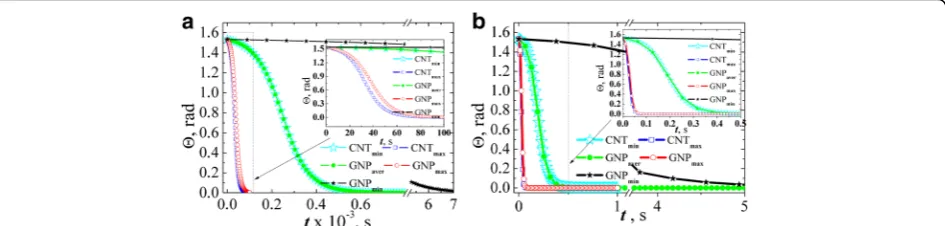
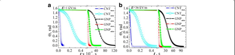
Figure 6 shows inclination angle of the particle relative to the direction of the applied field dependence of the field action time when Lx was evaluated by Eqs. (2) and (3). The results were found for two values of field strength: 1 kV/m (Fig. 6а) and 36 kV/m (Fig. 6b) suppos-ing that the particle is almost completely disordered at the initial time (Θ(t= 0) =π/2.05).
[image:7.595.65.538.590.703.2]There has been a clear correlation between the aspect ratio of the particles and the time of alignment by the electric field. Namely, maximum time for alignment is for particles with the lowest aspect ratio (GNPmin). For GNPmax and CNTmax, alignment time is almost equal, and equal time of alignment is for GNPaverand CNTmin.
Figure 7 shows depolarization factor values which was estimated by Eqs. (2) and (3) for GNPs and MWCNTs.
Lx is a geometrical factor and depends not on the abso-lute values of semi axes of the simulated ellipsoids but on their ratio. Thus, Lx is a direct function of the par-ticle aspect ratio.
That is, the depolarization factor is the main param-eter of the problem. Since its expression depends on the particle morphology and size a characteristic time of GNPs and MWCNTs rotation differ.
Figure 8 contents analogous to Fig. 6 dependences of inclination angle of the GNPs relative to the direction of the applied field on the field action time when LR was evaluated by Eq. (5). The results were found for two values of field strength: 1 kV/m (Fig. 8а) and 36 kV/m (Fig. 8b) supposing that the particles are almost com-pletely disordered at the initial time (Θ(t= 0) =π/2.05). For comparison, the results of calculations of the angle dependence for MWCNTs (Lxwas evaluated by Eq. (2)) are introduced at the same graphs.
Figure 9 shows dependences of inclination angle of the GNPs relative to the direction of the applied field on the field action time in approximation that GNP is a spher-oid with depolarization factor (4). Evaluation was per-formed for AC electric field strength 1 kV/m (Fig. 9а) and 36 kV/m (Fig. 9b) supposing that at initial time the particle is approximately disordered (Θ(t= 0) =π/2.05).
From the analysis presented in Fig. 9 data, the follow-ing conclusions were made: firstly, if we assume that the electric field axis is codirected with the x-axis of GNP, the rotation time increases significantly compared with the calculation in case of the field axis and GNP radius codirection. And this behavior is irrespective of the GNPs aspect ratio. Secondly, the course of the depend-ence is minimally different for the particles with differ-ent aspect ratios, and at a certain point of process time, more aligned particle is the particle with minimum aspect ratio GNPmin while GNPaver and GNPmax angles coincide. This behavior is due to the value of depolariz-ing factor which is close to 1 for the above cases.
Thus, the estimation have shown that the rotation time of carbon particles under AC electric field action depends on their morphology and aspect ratio. Note that
the model considers one particle embedded in polymer matrix while in composite, we have an ensemble of par-ticles with different initial angles of inclination. That is one of the reasons why real characteristic time of the whole network formation may be very different from the estimated time.
Besides, it is complicated to achieve such a distribu-tion of MWCNTs in composite mixture where each in-dividual tube is entangled. It is known that carbon nanotubes tend to tangle due to the interaction of their surfaces. Therefore, the real time of MWCNTs in com-posite mixture alignment is significantly higher than it was theoretically estimated. Besides, the viscosity of composite mixture with the same content of MWCNTs is higher than the viscosity of composite mixture with GNPs. All these factors prevent such a rapid alignment of MWCNTs in composite as it was estimated.
Electrical Properties of Solid Composites
Within the study, values of resistivity of the prepared GNPs/Larit 285 composites with aligned and with random filler distribution in epoxy matrix were experimentally found. Figure 10 presents the concentration dependences of electrical conductivity of GNPs/Larit 285 composites with aligned and with random filler distribution. Electrical
properties of the composite samples were investigated in longitudinal and perpendicular to the applied at composite fabrication electric field direction. Figure 11 presents con-centration dependences of conductivity for MWCNTs/ Larit 285 (а) [27] and GNPs/Larit 285 (b) composites in log-log scale.
The lowest values of the conductivityσ correspond to the samples of epoxy resin without filler (conductivity of 10−11 Sm/m). With GNPs adding to the composite, its conductivity increases and reaches the value of σ = 10 −6
Sm/m (this value is considered as percolation level) at GNPs contentсin composite ofφс= 2 wt% for the
com-posites with random filler distribution. For the GNPs/ Larit 285 composites with aligned filler distribution, per-colation concentration is ofφс = 0.84 wt%. Thus,
mate-rials of the identical composition are characterized by different values of percolation threshold depending on the method of preparation and filler distribution in the polymer matrix (aligned or random).
Conductivity of GNPs/Larit 285 composites smoothly increases with the increment of GNPs content for both types of the samples while the shape of the dependence is completely different for the MWCNTs/Larit 285 compos-ites obtained by the same method [27] (see Fig. 11). Con-centration dependence of conductivity of MWCNTs/Larit
Fig. 7Depolarization factor for GNPs and MWCNTs evaluated by Eqs. (2) and (3)
[image:8.595.56.542.87.258.2] [image:8.595.58.539.590.703.2]285 composites increases with the increment of MWCNTs content at low filler content until it reaches a plateau, then conductivity increases again. Such a differ-ence of conductivity concentration dependdiffer-ence can be ex-plained by another process of conductive network formation if the fillers are of different morphology. MWCNTs/epoxy composites are characterized by crossed framework structure formation while in GNPs/epoxy composites chained structure appears. GNPs addition to the polymer matrix smoothly increases the number of conductive links in composite. In case of entangled by themselves frame MWCNTs, there is an area where nano-tubes addition to the matrix has little effect on its conductivity.
Statistical percolation model operates with probabil-ities of particles in composite to create a conductive chain at their certain content. As it was shown in our paper, manufactured with electric field treatment, com-posites become conductive at lower content of carbon filler due to activation of dynamic percolation which is a phenomenon when conductive chain formation is stimu-lated by external influences at such a content of con-ductive particles in composite which is not enough for statistical percolation.
It should be noted that the existence of two types of per-colation transitions is a characteristic feature of composite materials which are in low-viscosity state during the manu-facture [34]. The higher value of percolation concentration cannot be changed by varying the manufacturing conditions of the composite since it is defined by statistical percolation theory. Statistical percolation threshold is defined by the filler type, its aspect ratio, surface state of polymer and filler, wettability, uniformity of filler distribution, and its content in polymer matrix. As we have shown, dynamical percola-tion threshold can be shifted by activating of filler particle movement in polymer matrix, by electric field action, and, thus, promoting a conductive network formation. The value of dynamic percolation threshold can be changed with method of composite manufacture change. We have estab-lished that in case of filler alignment under electric field ac-tion, dynamical percolation threshold is defined not only by the above parameters but also by parameters of the applied field and polymer matrix viscosity, filler morphology.
Conclusions
1. Nanocarbon-polymer composite material with aligned distribution of graphite nanoparticles in
[image:9.595.61.539.88.201.2]Fig. 9The evolution of the angle of GNPs inclination relative to the field direction estimated in spheroid approximation (Lxwas taken by the Eq. (4)) at AC electric field strength 1 kV/m (a) and 36 kV/m (b)
[image:9.595.62.539.546.702.2]epoxy matrix has been produced by exposing to a high-voltage AC electric field. The influence of elec-tric field treatment time, strength, and configuration of electric field on formation of aligned GNPs net-work in liquid polymer medium was investigated by optical microscopy.
2. It was shown that the influence of AC electric field at composite fabrication process leads to the
manifestation of two types of percolation transitions: statistical and dynamic ones. In addition, the aspect ratio of the filler particles and the character of the formation of the conducting cluster, depending on the shape of the particles, determine the shape of the
σ= f(c)dependence and the critical concentration of both dynamic and statistical percolation thresholds. 3. The effects of the morphology of the filler particles on
the process of nanocarbon alignment in polymer matrix under AC electric field have been investigated by estimating of carbon nanotube and graphite nanoplatelet rotation time using an analytical model based on effective medium approach. The theoretical evaluation of characteristic time of carbon
nanoparticle of different morphology rotation under AC electric field action have shown that rotation time of carbon nanoparticle is determined by its
depolarization factor which in turn depends directly on the aspect ratio of particle.
4. The investigation of concentration dependences of conductivity of composites GNPs/Larit 285 with aligned by AC electric field action filler distribution and random filler distribution in epoxy matrix have shown that under AC electric field action
composites, percolation threshold decreases essentially fromϕc= 2 wt% for composites with random filler distribution of GNPs toϕc= 0.84 wt%
for the obtained under AC electric field action GNPs/Larit 285 composites.
Abbreviations
AC:Alternative current; AFM: Atomic force microscopy; CNTs: Carbon nanotubes; DC: Direct current; GNPs: Graphite nanoplatelets;
MWCNTs: Multiwall carbon nanotubes; SEM: Scanning electron microscopy
Authors’contributions
OY, LM, VZ, GD, YP, and OL studied literature on the subject of investigation. OY, GD, and LM developed the sample preparation technique. LM contributed the reagent/material tools. OY and GD prepared specimens and carried out the measurements. LV, OL, OY, LM, YP, and GD contributed the data analysis and participated in a scientific discussion. LM and OY made the main contribution to goal setting. VZ performed a program for the calculations in Maple 13, submitted suggestions to the used analytical model, and participated in the discussion of results. OY conducted numerical calculations and drafted the manuscript. LV, OL, OY, and LM contributed the revision of the manuscript. OY finalized the manuscript. All authors read and approved the final manuscript.
Competing interests
The authors declare that they have no competing interests.
Publisher’s Note
Springer Nature remains neutral with regard to jurisdictional claims in published maps and institutional affiliations.
Received: 31 December 2016 Accepted: 22 July 2017
References
1. Zhang W, Dehghani-Sanij AA, Blackburn RS (2007) Carbon based conductive polymer composites. J Mater Sci 42:3408–3418
2. Carratalá-Abril J, Rey-Martínez L, Beneito-Ruiz R, Vilaplana-Cerdá J (2016) Development of carbon-based composite materials for energy storage. Mater Today Proc 3:240–245
3. Luo X, Chung DDL (1999) Electromagnetic interference shielding using continuous carbon-fiber carbon-matrix and polymer-matrix composites. Compos Part B 30:227–231
4. Vovchenko L, Yu P, Matzui L, Ovsiienko I, Oliynyk V, Launetz V (2012) Shielding coatings based on carbon-polymer composites. Surf Coat Tech 211:196–199 5. Yu Y, Song S, Bu Z, Gu X, Song G, Sun L (2013) Influence of filler waviness and aspect ratio on the percolation threshold of carbon nanomaterials reinforced polymer nanocomposites. J Mater Sci 48(17):5727–5732 6. Silva J, Lanceros-Mendez S, Simoes R (2014) Effect of cylindrical filler
aggregation on the electrical conductivity of composites. Phys Lett A 378(40):2985–2988
7. Ehsani A, Babaei F, Mostaanzadeh H (2015) Electrochemical and optical investigation of conductive polymer and MWCNT nanocomposite film. J Braz Chem Soc 26(2):331–337
8. Big DM (1995) Thermal conductivity of heterophase polymer compositions. In: thermal and electrical conductivity of polymer materials. Adv Polym Sci 119:1–30 9. Li J, Ma PC, Sze CW, Kai TC, Tang BZ, Kim JK (2007) Percolation threshold of
polymer nanocomposites containing graphite nanoplatelets and carbon nanotubes. ICCM, http://repository.ust.hk/ir/Record/1783.1-50129 10. Bychanok DS, Shuba MV, Kuzhir PP, Maksimenko SA, Kubarev VV, Kanygin MA,
[image:10.595.59.540.88.205.2]Sedelnikova OV, Bulusheva LG, Oktorub AV (2013) Anisotropic electromagnetic properties of polymer composites containing oriented multiwall carbon nanotubes in respect to terahertz polarizer applications. J Appl Phys 114: 114304 -1-7
11. Kumar S, Kaur H, Kaur I, Dharamvir K, Bharadwaj LM (2012) Magnetic field-guided orientation of carbon nanotubes through their conjugation with magnetic nanoparticles. J Mater Sci 47:1489–1496
12. Kumar MS, Lee SH, Kim TY, Kim TH, Song SM, Yang JW, Nahm KS, Suh EK (2003) DC electric field assisted alignment of carbon nanotubes on metal electrodes. Solid State Electron 47:2075–2080
13. Prasse T, Cavaille’JY, Bauhofer W (2003) Electric anisotropy of carbon nanofibre/epoxy resin composites due to electric field induced alignment. Compos Sci Technol 63:1835–1841
14. Larijani MM, Khamse EJ, Asadollahi Z, Asadi M (2012) Effect of aligned carbon nanotubes on electrical conductivity behavior in polycarbonate matrix. Bull Mater Sci 35(3):305–311
15. Zhu YF, Ma C, Zhang W, Zhang RP, Koratkar N, Liang J (2009) Alignment of multiwalled carbon nanotubes in bulk epoxy composites via electric field. J Appl Phys 105(5):054319–054316
16. Oliva-Avil’es AI, Avil’es F, Sosa V, Oliva AI, Gamboa F (2012) Dynamics of carbon nanotube alignment by electric fields. Nanotechnol 23:465710–465710 17. Chen Z, Hu W, Guo J (2004) Fabrication of nanoelectrodes based on
controlled placement of carbon nanotubes using alternating-current electric field. J Vac Sci Technol B 22(2):776–780
18. Martin CA, Sandler JKW, Windle AH, Schwarz MK, Bauhofer W, Schulte K, Shaffer MSP (2005) Electric field-induced aligned multi-wall carbon nanotube networks in epoxy composites. Polymer 46:877–886 19. Oliva-Avile’s AI, Avile’s F, Sosa V, Seidel GD (2014) Dielectrophoretic
modeling of the dynamic carbon nanotube network formation in viscous media under alternating current electric fields. Carbon 69:342–354 20. Wang H, Zhang H, Zhao W, Zhang W, Chen G (2008) Preparation of
polymer/oriented graphite nanosheet composite by electric field-inducement. Compos Sci Technol 68(1):238–243
21. Pang H, Chen C, Zhang YC, Ren PG, Yan DX, Li ZM (2011) The effect of electric field, annealing temperature and filler loading on the percolation threshold of polystyrene containing carbon nanotubes and graphene nanosheets. Carbon 49:1980–1988
22. Lazarenko O, Vovchenko L, Matzui L, Perets J (2011) The electronic transport properties of the composites with nanosized carbon fillers. Mol Cryst Liq Cryst 536(1):72/[304]–80/[312]
23. Perets YS, Matzui LY, Vovchenko LL, Prylutskyy YI, Scharff P, Ritter U (2014) The effect of boron nitride on electrical conductivity of nanocarbon-polymer composites. J Mater Sci 49(5):2098–2105
24. Yakovenko OS, Matzui LYu, Perets YuS, Ovsiienko IV, Brusylovets OA, Vovchenko LL, Szroeder P. Effects of dispersion and ultraviolet/ozonolysis functionalization of graphite nanoplatelets on the electrical properties of epoxy nanocomposites. In book: Nanophysics, Nanophotonics, surface studies, and applications, 2016(183). p. 477–491
25. Laurent C, Flahaut E, Peigney A (2010) The weight and density of carbon nanotubes versus the number of walls and diameter. Carbon 48(10):2994–2996 26. Yakovenko O, Matzui L, Vovchenko L, Zhuravkov A (2014) Development of
carbon nanotube-polymer composites with oriented distribution of MWCNTs induced by electric field. Phys Stat Solidi A 211(12):2718–2722 27. Matzui LY, Yakovenko OS, Vovchenko LL, Oliynyk VV, Zagorodnii VV, Launets
VL. Conductive and shielding properties of MWCNTs/polymer
nanocomposites with aligned filler distribution. In book: NATO science for peace and security series B: physics and biophysics 2016. p. 251-271 28. Landau LD, Lifshitz EM, Pitaevskii LP (1984) Electrodynamics of continuous
media, vol 8, 2nd edn. Butterworth-Heinemann, Oxford
29. Usanov DA, Skripal AV, Romanov AV (2011) Complex permittivity of composites based on dielectric matrices with carbon nanotubes. Tech Phys 56(1):102–106 30. Melnichenko M, Yakovenko O, Matzui L, Vovchenko L, Oliynyk V, Launetz V.
Electrodynamic properties of the nanocarbon/polymer composites with aligned by magnetic field secondary non-conductive component. Proc SPIE 9519, Nanotechnol VII 2015;9519:951918-951910
31. Ebbesen TW, Lezec HJ, Hiura H, Bennet JW, Ghaemi HF, Thio T (1996) Electrical conductivity of individual carbon nanotubes. Nature 382:54–56 32. Stelmakh OI, Matzui LY, Vovchenko LL (2007) Electrical resistivity of
composite materials based on thermoexfoliated graphite. Phys Chem Solid State 8(2):408–413
33. Stelmakh OI, Vovchenko LL, Matzui VI (2004) Electrical and thermal conductivity of graphite-metal composites. Funct Mat 11(3):546–550 34. Kovacs JZ, Velagala BS, Schulte K, Bauhofer W (2007) Two percolation thresholds
![Fig. 3 Optical images of 0.05 wt.% MWCNTs/Larit 285 composite under AC electric field action (frequency of 15 kHz, strength of 83.3 kV/m) (embedded electrodes):Image size 10,8 × 8,0 mm a – before electric field action; b – after 12 min; c – after 26 min; d – after 60 min of electric field action.2 [26]](https://thumb-us.123doks.com/thumbv2/123dok_us/8847318.933562/5.595.56.541.475.695/optical-composite-electric-frequency-strength-embedded-electrodes-electric.webp)
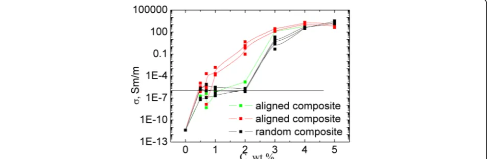
![Fig. 11 Concentration dependence of conductivity of MWCNTs/Larit 285 (а) [27] and GNPs/Larit 285 (b) in log-log scale](https://thumb-us.123doks.com/thumbv2/123dok_us/8847318.933562/10.595.59.540.88.205/concentration-dependence-conductivity-mwcnts-larit-gnps-larit-scale.webp)
![μ Oxo bis{diethoxy[salicylaldoximato(2–)]niobium(V)}](data:image/gif;base64,R0lGODlhAQABAIAAAP///wAAACH5BAEAAAAALAAAAAABAAEAAAICRAEAOw==)