Modeling and control of a spherical rolling robot Using Model Reference
adaptive control
T.Purushotham
1, Soma Venkata Subbaiah
21PG Scholar, Department of EEE, JNTU Anantapur, Andhra Pradesh, India
2PG Scholar, Department of EEE, JNTU Anantapur, Andhra Pradesh, India
---***---Abstract— Generally the conventional controller not
well tuned. Due to the abstraction of the real system, unmodeled dynamics, parameter variations and disturbance results in poor performance. In our paper which presents the control of a spherical rolling robot based on fuzzy control and a adaptive control theory based on learning algorithm. This proposed control schemes assure asymptotic stability of the system in a closed space based on a neuro fuzzy control and a conventional controller. The derived parameter updating rules of the neuro-fuzzy system using MRAS theory can be proved by its lyapunov function. Simulation results of this proposed scheme shows that without knowing dynamic equations we can eliminate the steady state error and we can enhance the transient response of the spherical rolling robot.
One of the reference paper describes about a prototype and analytical studies of the spherical rolling robot by using a new design of the nonholonomic robot constraints. The mathematical model of the spherical rolling robots motion was developed by using the nonholonomic constraints. It has shown experimentally that the model subjected areas well with the results of the system. So many methods were developed for planning feasible, minimum time and minimum energy trajectories for the robot.
Index Terms— Adaptive neuro-fuzzy control, sliding-mode learning algorithm, spherical rolling robot.
I. INTRODUCTION
Now a days need of mobile robots in variety of non identical applications such as security surveillance, search and rescue, children education and
entertainment increased. Spherical rolling
mechanisms have more
advantages over to wheeled and legged mechanisms. All mechanical and electrical components along with the actuation mechanisms, are securely embedded in a spherical shell rolling over ground surface. By using nonholonomic constraints, the motion of a spherical rolling can be controlled without having slipping. Hence they belonged to nonholonomic mechanical systems.
The basic difference between spherical and wheeled rolling motions is the instantaneous number of degrees of freedom (DOFs) between the mobile body and the ground surface. The instantaneous mobility is higher than that of a wheel because spherical robot rotate around the transverse and longitudinal axes.
However, spherical rolling robot their direction of motion mechanisms can easily changed than the wheeled mechanisms. Compare to wheeled and legged mechanisms, spheres cannot fall over. The general problem of stability of equilibrium frequently encountered in mobile robotics is naturally avoided with the use of spherical rolling. On the other hand, for describing the dynamics spherical rolling system the high complex nonlinear equations are needed.
© 2015, IRJET ISO 9001:2008 Certified Journal Page 1174
II. MATHEMATICAL MODEL OF A SPHERICAL
ROLLING ROBOT
Description:
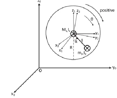
The spherical rolling robot is a spherical aluminum shell and is assembled in two halves. Each hemispherical of the spherical rolling robots half-shell contains a receiver, motor assembly, rotor(s), and batteries for a rotor axes. Fig. shows that the two halves of the spherical rolling robot prior to assembly. The motor casing and holder for the batteries are attached to the shell by screws which are counter sunk so as to keep the outer side of the spherical shell free from irregularities. On the outer surface of the robot, six cross-like markings are made in a tetrahedral pattern with black tape. These markings are used by the camera to locate the spherical rolling robot from a top view. An important property of the robot is that its center of mass lies exactly at the geometrical center of the spherical ball. The ball is so assembled that every component is a corresponding identical component of the placed diametrically opposite on the sphere. The result of this property is that center of mass of the spherical rolling robot always lies above its attached point,. Thus, the ball does not extend to ‘tip over.’ This point is important in the Development of the analytical model for the spherical rolling robot dynamics. Signals were sent to the spherical rolling robot by using a futaba two channel amplitude modulation transmitter. This two channels of the transmitter were controlled by using voltage outputs.
This spherical rolling robot can be classified in to three types of the system of the rigid body. They are
1) The spherical robot outer shell and its components
2) The single rotor was placed on the z-axis
3) The two rotors were placed on the x-axis
Fig 1: Spherical Rolling on a plane
PID controller
Mass conversation between the bodies
Fuzzy logic controller of the system
Neural network controller of the system
Thickness
Roll and plate loop
[image:2.612.336.535.471.639.2]The mathematical modeling of the spherical rolling robot is presented by the model reference adaptive control (MRAC) theory. The main difference of the spherical rolling robot is the viscous friction has to be added into the equations of the motion of the spherical rolling robot.
Fig 2. Modeling of rolling motion about the traversal axis for overall translation along o-y
© 2015, IRJET ISO 9001:2008 Certified Journal Page 1175
ωs = − θ˙I (2)
vs = − R˙θj (3)
rp0 =l sin(α − θ)j − l cos(α − θ)k (4)
ωp =(α˙ − θ˙)i (5)
vp =(−Rθ˙ + (α˙ − θ˙)l cos(α − θ)j +(α˙ − θ˙)l sin(α − θ)_k (6)
The above equations shows that the viscous friction of the spherical rolling robot which operates in between the sphere and surface. When the loss obtained with response of viscous friction can be written in energy dissipation function which depends on system velocities and the damping constant S =1/2ζq˙i2=1/2 ζ(θ˙2 + α˙ 2). (7)
The equations of spherical rolling motion of a mechanical system can be written as follows:
M (q(t)) q(¨t) + C(q(t), q(˙t))+ G(q(t)) = u(t). (8)
III. DESCRIPTION OF MRAC
A control system is a device that works on controls the dynamics of any plants or process. Adaptive control is one of the most widely used control strategies to design the advanced control systems for good performance and accuracy.
Model Reference Adaptive Control (MRAC) is a direct
control adaptive strategy with the some
modifications of the adjustable controller parameters and an adjustable mechanism to change them. From the comparison of the very well-known and simple structure fixed gain PID controllers, adaptive controllers are more effective to control the unknown parameter variations of the model reference adaptive control and environmental changes of the system. An adaptive controller is considered in two loops, an outer loop or normal feedback loop of model reference adaptive control and an inner loop or
parameter adjustment loop of the model reference adaptive control. This paper deals with the designing of the adaptive controller with model reference adaptive control (MRAC) scheme by using MIT rule to control the second order system.
Principle of working
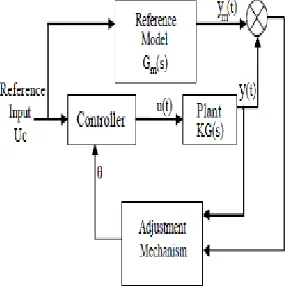
Model Reference Adaptive control (MRAC) strategy works on the principle of adjusting the controller parameters to design the adaptive controller therefore the output of the actual plant adjusts the output of a reference model by using the same reference input.
Components
Reference Model: Reference model is used to give an ideal responses of the adaptive control system to the reference input.
Controller: It is described by a adjustable set of parameters. This paper presents only one parameter θ is used to describe the control law. The value of θ is automatically dependent on the thesaurus gain.
Adjustment Mechanism: By using adjustment mechanism to change the parameters of the controller therefore actual plant could track the reference model
.Mathematical approaches of MIT rule, the theory of Lyapunov and augmented error can be used to develop the adjustment mechanism. In our paper we are using MIT rule with the Normalized Algorithm and the technique is to be referred as Modified MIT rule.
© 2015, IRJET ISO 9001:2008 Certified Journal Page 1176
[image:4.612.90.234.183.328.2]e(t) = y(t) –y(tm) ………(9)
Fig 3: Model Reference Adaptive Control System
THE GENERAL IDEA BEHIND MODEL REFERENCE ADAPTIVE CONTROL (MRAC) IS TO CREATE A CLOSED LOOP CONTROLLER WITH PARAMETERS VARATIONS THAT CAN BE UPDATED TO ALTER THE RESPONSE OF THE MRAC SYSTEM. THE OUTPUT OF THE MRAC SYSTEM IS COMPARED TO A DESIRED RESPONSE FROM THE REFERENCE MODEL.THE CONTROL PARAMETERS ARE UPDATED BASED ON THIS ERROR.THE MAIN GOAL FOR THE MRAC SYSTEM PARAMETERS IS TO CONVERGE THE IDEAL VALUES OF THE SYSTEM THAT CAUSED TO THE PLANT RESPONSE OF THE SYSTEM TO MATCH THE RESPONSE OF THE REFERENCE MODEL. FOR AN EXAMPLE, WE MAY BE TRYING TO CONTROL THE POSITION OF A ROBOT ARM NATURALLY VIBRATES.WE NEEDED ACTUALLY THE ROBOT ARM OF THE SYSTEM TO MAKE QUICK MOTIONS WITH FEW OR NO VIBRATION. BY USING MRAC, WE COULD CHOOSE THE REFERENCE MODEL OF THE SYSTEM THAT COULD RESPOND IMMEDIATELY TO A STEP INPUT WITH A SHORT SETTLING TIME. WE COULD THEN BUILD UP A CONTROLLER THAT WOULD ADAPT TO MAKE THE ROBOT ARM MOVE JUST LIKE
THE REFERENCE MODEL.
MRAC is a widely subjected area with so many different applications and methods. The purpose of
this paper is to introduce the design of an MRAC using the MIT rule.
IV. ADAPTIVE NEURO-FUZZY CONTROL APPROACH
A. Control Scheme and the Adaptive Neuro-Fuzzy
Inference System
In real-time applications, structural and parametric uncertainties such as un modeled dynamics and physical disturbances cause unwanted effects on the system behavior. Like tire dynamics, the spherical rolling robot dynamics are affected by the slip ratio and variations of the surface conditions. Thus, spherical rolling robots should have an adaptive intelligent controller with respect to the high uncertainty and the variation in the surface properties. While conventional controllers struggle with these problems, neuro-fuzzy control can overcome these limitations and provide higher robustness.
[image:4.612.340.547.438.535.2]© 2015, IRJET ISO 9001:2008 Certified Journal Page 1177
[image:5.612.47.261.162.267.2]Fig 5. Block diagram of the proposed control scheme for the PID controller case
Fig 6. Forward Neural netwrok
Proportional derivative:
(PD) or PID controller and a neuro-fuzzy controller are working in parallel. The conventional controller is used to guarantee the global asymptotic stability of the system in a compact space. The PD control law is written as follows:
e = kpe +Kde ……….(9)
Where e = θd – θ is the feedback error, θd is the desired position value, and Kp and Kd are the controller gains.
V. SIMULATION RESULTS
The numerical values used in [4], [6], and [9] are considered for the numerical values in this study which are Ms = 3 kg, mp = 2 kg, R = 0.2 m, l = 0.075 m, and g = 9.81 m/s2. The damping coefficient ζ in the equations of motion is set to 0.2, and the sampling period of the simulations is set to 0.001 s. The number of membership functions for inputs 1 and 2 is chosen as I = J = 3 for all the simulations.
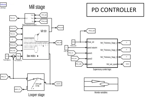
VI. SIMULATION MODEL WITH PD CONTROLLER
Mill stage Looper stage Continuous pow ergui 0.5 Theta setpoint Pthick_in0 speed setpoint speed1 speed2 speed3 Ref_Thickness_Stage_1 Ref_Thickness_Stage_2 Ref_Thickness_Stage_3 Ref_exit_speed Supervisory control logic 1 Pvel_end 0.01 Pthick_out0 PD(s) PD Controller1 Monitor variables Vout_2 Tout_2 Tin_2 Vin_2 Mass conservation for stage 1
[image:5.612.324.536.429.603.2]Pthick_out1 Pvel_out1 Coiler -T-tension_12 Laccum_1 theta_12 Pthick_out0 Pvel_in1 Pvel_in1 [Pvel_out2] Pvel_in1 Pthick_out0 Pthick_out0 Pvel_out1 Pvel_out1 Pthick_out0 [Pvel_in2]
-T-Fig 7. Simulation model of roller
Proportional gain: (4.000)
Derivative gain: (1.1729)
Fig 8. FIS editor
© 2015, IRJET ISO 9001:2008 Certified Journal Page 1178 Mill stage Looper stage Continuous pow ergui 0.5 Theta setpoint Pthick_in0 speed setpoint speed1 speed2 speed3 Ref_Thickness_Stage_1 Ref_Thickness_Stage_2 Ref_Thickness_Stage_3 Ref_exit_speed Supervisory control logic Scope1 1 Pvel_end 0.01 Pthick_out0 PD(s) PD Controller1 Monitor variables Vout_2 Tout_2 Tin_2 Vin_2 Mass conservation for stage 1
[image:6.612.319.546.99.278.2] [image:6.612.324.565.378.541.2] [image:6.612.36.255.408.573.2]ud uq id iq theta w_e MRAS Pthick_out1 Pvel_out1 Coiler -T-tension_12 Laccum_1 theta_12 Pthick_out0 Pvel_in1 Pvel_in1 [Pvel_out2] Pvel_in1 Pthick_out0 Pthick_out0 Pvel_out1 Pvel_out1 Pthick_out0 [Pvel_in2]
-T-Fig 9. MRAC CONTROLLER
The numerical values considered in this study are:
Ms = 3 kg,
mp = 2 kg, R = 0.2 m, l = 0.075 m, and g = 9.81 m/s2.
Fig 10. Subsystem of FNN (2-layered)
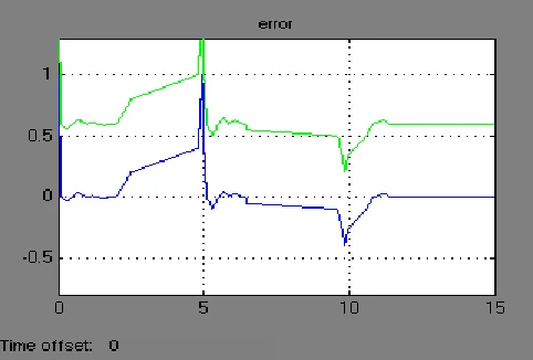
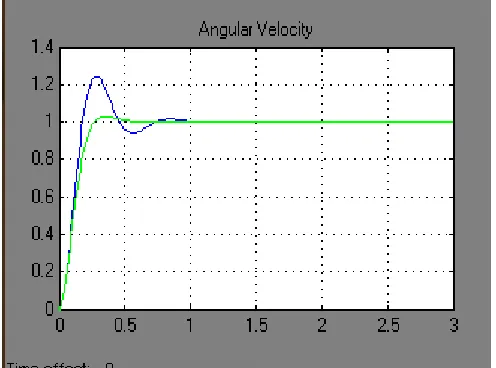
Fig. 11. Velocity responses of the system for the PD and PD+FNN controllers.
© 2015, IRJET ISO 9001:2008 Certified Journal Page 1179
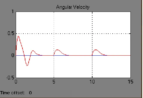
[image:7.612.35.283.385.569.2]Fig. 13. Velocity responses of the system for the PID and PID+FNN controllers.
© 2015, IRJET ISO 9001:2008 Certified Journal Page 1180
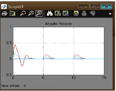
Fig. 15. Velocity responses of the system for the PID and PID+FNN controllers when the damping
coefficient is set to 0.5 with a noise level SNR = 20
dB.
[image:8.612.35.279.395.573.2]© 2015, IRJET ISO 9001:2008 Certified Journal Page 1181
© 2015, IRJET ISO 9001:2008 Certified Journal Page 1182
Fig. 18. Control signals coming from the PID controller and the FNN and adaptive when the damping coefficient is set to 0.2, and 0.5 etc respectively
VII. Conclusions
In this paper, an adaptive neuro-fuzzy controller with MRAS theory-based online learning has been elaborated for velocity control of a spherical rolling robot subject to parameter variations and uncertainties in its dynamics. The simulation studies show that the proposed adaptive neuro-fuzzy control scheme (a conventional controller working in parallel with the FNN) results in better performance and higher robustness when compared to the conventional stand-alone controller. The proposed control algorithm is able to not only eliminate the steady-state error in the case of the conventional PD stand-alone controller but also improve the transient response performance of the system in the case of the conventional PID stand-alone controller. Owing to the MRAS-theory-based online learning algorithm, the parameters of the controller are automatically adapted to cope with the parameter variations and uncertainties. In addition to its robustness, the control approach with the proposed learning algorithm is computationally simple, particularly
when compared to the gradient descent and the evolutionary algorithms.
VI. REFERENCES
[1] J. Alves and J. Dias, “Design and control of a spherical mobile robot,”in Proc. Inst. Mech. Eng., Part I, J. Syst. Control Eng., 2003, vol. 217,pp. 457–467.
[2] C. Camicia, F. Conticelli, and A. Bicchi, “Nonholonomic kinematics and dynamics of the spherical,” in Proc. IEEE/RSJ Int. Conf. Intell. RobotsSyst., Takamatsu, Japan, 2000, vol. 1, pp. 805– 810.
[3] A. Halme, T. Schonberg, and Y.Wang, “Motion control of a spherical mobile robot,” in Proc. 4th Int. Workshop Adv. Motion Control, Albuquerque,NM, 1996, vol. 1, pp. 259–264.
[4] A. A. H. Javadi and P. Mojabi, “Introducing glory: A novel strategy foran unidirectional spherical rolling robot,” J. Dyn. Syst., Meas., Control,vol. 126, pp. 678– 683, 2004.
[5] R. Mukherjee, M. A. Minor, and J. T. Pukrushpan, “Motion planning for a spherical mobile robot: Revisiting the classical ball–plate problem,”ASME J. Dyn. Syst. Meas. Control, vol. 124, pp. 502–511, Dec. 2002.
[6] V. A. Joshi and R. N. Banavar, “Motion analysis of a spherical mobile robot,” Robotica, vol. 27, pp. 343– 353, 2009.
[7] V. A. Joshi, R. N. Banavar, and R. Hippalgaonkar, “Design and analysis of a spherical mobile robot,” Mech. Mach. Theory, vol. 45, no. 2, pp. 130–136, Feb. 2010.
© 2015, IRJET ISO 9001:2008 Certified Journal Page 1183
[9] Y. Ming, D. Zongquan, Y. Xinyi, and Y. Weizhen, “Introducing HIT spherical robot: Dynamic modeling and analysis based on decoupled subsystem,” in Proc. IEEE Int. Conf. Robot. Biomimetics, Harbin, China,2006, pp. 181–186.