© 2016, IRJET | Impact Factor value: 4.45 | ISO 9001:2008 Certified Journal | Page 1316
Optimization of Electrical Discharge Machining Process Parameters
Using Flushing and Drilled Tool
Rahul Gupta
1, Pooja Bibave
1, Ashish Shelke
1, Rohit Kesarkar
1, Prasad Bari
2, Santosh Chauhan
21
B.E Student, Dept. of Mechanical Engineering, FCRIT, Vashi, Maharashtra-400703, India
2Assistant Professor, Dept. of Mechanical Engineering, FCRIT, Vashi, Maharashtra-400703, India
---***---Abstract -
Electric Discharge Machining (EDM) is athermo-electric non-traditional machining process in which material removal takes place between a pair of electrodes which are submerged in a dielectric medium. In present study the effect of Flushing discharge and tool hole diameter on MRR has been studied along with current, voltage and spark on time. The optimization was done using Design of Experiments (DOE). It is observed experimentally that increase in flushing discharge increases the MRR. Also increase in tool hole diameter increases MRR up to a certain value and decreases with further increase in diameter.
Key Words: EDM, Flushing, Dielectric medium, MRR, DOE.
1. INTRODUCTION
Electro Discharge Machining (EDM)[1] is a non-conventional machining process which is more efficient than conventional machining process due to ease of machining of difficult-to machine materials with complex shapes. It is also used for machining the materials which are hard enough to cut by traditional processes. It has many applications in industries like aerospace, automobile, general engineering, etc. EDM performance is mainly dependent on factors like flushing discharge, pulse on time, current, voltage, tool geometry.
Flushing [6] is the greatest key role which provides correct circulation of dielectric liquefied in any electrical discharge machining operation. If removed particles are not flushed thoroughly, they act as obstacles in the small gap between tool and work piece. Flushing is the procedure of presenting clean strained dielectric liquid into the spark gap. Fig-1.1 shows the basic principal of flushing.
By scrutiny of the published research work, the paper addresses the issue that an alternate type of tool like hollow tube electrode may have a positive impact on MRR with low tool wear rate due to improved flushing conditions. Hollow tool is particularly useful for drilling holes with low tool wear rate. It was found that while machining the same length of Inconel718 with a solid tool it takes approximately 40% more machining time than taken by a hollow tool [7]. Hollow tool also helps in minimizing the dielectric fluid degradation. Consequently, the approach light is cost effective with higher
yield, and reduced material and energy loss. The work will be carried out using Drilled tool varying the diameters[9] of the hole and finding the optimum combination of parameters and experimentally conform the results [3].
[image:1.595.314.560.289.451.2]Fig -1.1: Flushing [10]
1.1 Experimental Setup
The Experiment set was conducted on an EDM machine, CHMER 50-EZ using 16mm diameter copper tool[2] electrode and variable flushing discharge for studying the effect of flushing discharge on MRR.
For studying the effect of tool hole diameter on MRR the tool was drilled by 4mm, 6mm and 8mm diameter. The experiment was conducted on EN-353[7] steel using EDM-30 oil as dielectric. The properties of work piece and tool electrode are listed in the following table:
Table -1.1.1: Properties of Cu Electrode [2]
Property Description
Density 8960 kg/m3
Melting point 1083C
Thermal conductivity 401 W/mK
Electrical resistivity 1.673e-008 ohm
© 2016, IRJET | Impact Factor value: 4.45 | ISO 9001:2008 Certified Journal | Page 1317 Table -1.1.2: Properties of EN-353 [7] steel work piece
Property Description
Density 8904 kg/m3
Melting point 1510C
Thermal conductivity 51.9 W/mK
Hardness 260 HB
[image:2.595.298.567.350.437.2]Dimension 130mm*50mm*30 mm
Table -1.1.3: Properties of Dielectric EDM-30
Property Description
Density 826 kg/m3
Flash point 1020C
Burn Rate 150 A
Boiling Point 149oc
Viscosity at 400c 3.5 cst
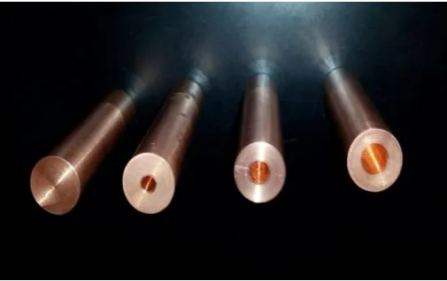
[image:2.595.36.289.378.537.2]Fig-1.1.1 and Fig-1.1.2 shows the different copper tool electrode and work piece EN-353 steel respectively.
[image:2.595.303.563.470.554.2]Fig -1.1.1: Solid and drilled Cu electrode
Fig -1.1.2: Work piece EN-353 steel
Design of experiments was conducted using Taguchi's approach [4]. The value of input parameters with their levels are shown in Table 1.1.4.Since the number of parameters is three and each parameter has three levels, using the orthogonal array selector, the L9 array is selected. The array obtained is shown in Table 1.1.5 and Table 1.1.6.
Table -1.1.4: Value of Input Parameters
Parameters Level
1 2 3
Discharge Current (A) 8 10 12
Spark ON Time (µs) 100 150 200
Flushing Discharge (mm3/min)
2631 3946 5260
Hole Diameter of
Electrode (mm) 4 6 8
Table -1.1.5: L9 Array for Flushing
Sr.No. Current (amp) Pulse ON time (µs) Flushing (mm3/min)
1 8 100 2631
2 8 150 3946
3 8 200 5260
4 10 100 3946
5 10 150 5260
6 10 200 2631
7 12 100 5260
8 12 150 2631
9 12 200 3946
Table -1.1.6: L9 Array for Drilled Electrode
Sr.No. Current (amp) Pulse ON time (µs) Hole Diameter (mm)
1 8 100 4
2 8 150 6
3 8 200 8
4 10 100 6
5 10 150 8
6 10 200 4
7 12 100 8
8 12 150 4
9 12 200 6
As the process of removing work piece to measure weight after each reading is cumbersome, the MRR was calculated by determining volume of the material removed, after performance of the entire experiment. Following formulae are used for calculation:
Volume of material loss (mm3) = V =A*dc ……….…. (1.1) Material Removal Rate (mm3/min) = V / T .……….… (1.2) Where,
A= Area of the impression dc = Depth of cut (mm), Tm = machining time (min)
[image:2.595.35.292.577.732.2]© 2016, IRJET | Impact Factor value: 4.45 | ISO 9001:2008 Certified Journal | Page 1318
1.2 Observation
[image:3.595.308.562.97.264.2]The MRR for each combination of experiments is calculated using equation 1.1 and 1.2. The observation table for Flushing discharge and Tool hole diameter are as shown in Table 1.2.1 and Table 1.2.2 respectively.
Table -1.2.1: Observation table for Flushing discharge
Sr. No. Current (amp) time (µs) Pulse ON (mmFlushing 3/min)
MRR(mm3/min)
1 8 100 2631 9.6504
2 8 150 3946 11.1179
3 8 200 5260 9.8871
4 10 100 3946 21.1630
5 10 150 5260 19.3008
6 10 200 2631 16.3013
7 12 100 5260 22.7600
8 12 150 2631 22.6600
[image:3.595.35.295.214.306.2]9 12 200 3946 19.4560
Table -1.2.2: Observation table for Drilled Electrode
Sr.No. Current (amp) Pulse ON time (µs) Hole Diameter (mm) (mmMRR 3/min)
1 8 100 4 8.9600
2 8 150 6 12.6460
3 8 200 8 9.0470
4 10 100 6 20.3260
5 10 150 8 13.4000
6 10 200 4 13.7000
7 12 100 8 18.2700
8 12 150 4 16.4800
9 12 200 6 18.0200
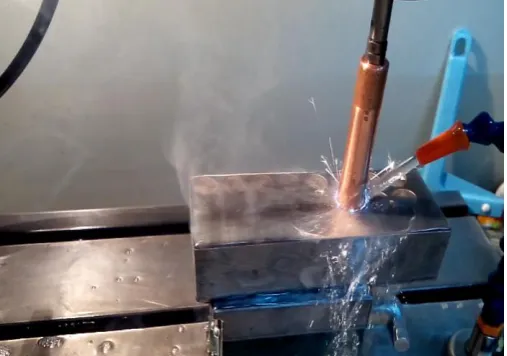
Figure 1.2.1, 1.2.2, and 1.2.3 shows the flushing arrangement for different discharge.
Fig -1.2.1: Flushing arrangement for discharge =2631 mm3/min
[image:3.595.309.564.298.469.2]Fig-1.2.2: Flushing arrangement for discharge=3946 mm3/min
Fig-1.2.3: Flushing arrangement for discharge =5260 mm3/min
2. Result and Analysis
The experimental results are analyzed for MRR to the flushing discharge and tool hole diameter. For analysis MINITAB-17 software was used. The subsequent graphs are plotted by implementing DOE. Table displays the result obtained, along with the combination of input parameters. Two types of subsequent graphs are plotted.
2.1 Main Effect Plot
[image:3.595.36.292.343.434.2] [image:3.595.36.290.489.667.2]© 2016, IRJET | Impact Factor value: 4.45 | ISO 9001:2008 Certified Journal | Page 1319 Chart -2.1.1: Main Effect Plot for flushing discharge
Chart -2.1.2: Main Effect Plot for flushing discharge
From the main effects plot, it can be inferred that within experimental limits, the following combination will give the best value of MRR:
For Flushing:-
1. Current: 12 amp 2. Pulse ON time: 100 µs
3.
Flushing Discharge : 3946 mm3/secFor Drilled Electrode:-
1. Current: 12 amp 2. Pulse ON time: 100 µs 3. Hole Diameter: 6 mm
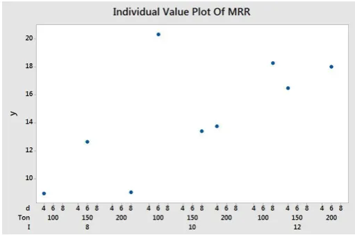
2.2 Individual Value Plot
This graph takes all the possible combinations and plots each result accordingly. From Table 1.1.5 it is clear that each set of readings has a unique combination of input parameters. It gives graph for each value separately. This is especially useful when numbers of observations are relatively less.
Chart -2.2.1: Individual Value Plot for flushing discharge
Chart -2.2.2: Individual Value Plot for drilled electrode
2.3 Validation
[image:4.595.307.563.294.463.2]The optimum combination obtained from main effect plot must be verified in order to validate the experiment. Hence the experiment is performed again but for a small set of readings and only considering the parameter values in the obtained optimum combination. The results of validation are listed in Table 2.3.1.
Table -2.3.1: Validation
Current
(amp) ON time (µs) Discharge/Hole Dia. (mm3/min) MRR
Flushing 12 100 5260 22.76
Drilled Electrode
© 2016, IRJET | Impact Factor value: 4.45 | ISO 9001:2008 Certified Journal | Page 1320
3. CONCLUSIONS
1. From the observation, as the flushing discharge increases the Metal Removal Rate also increases gradually.
2. Experimental result shows that factor of flushing is important to remove gaseous and solid debris generated during EDM process also the MRR tend to increase gradually with increase of tool hole diameter up to 6mm and further increase in diameter results in decrease of MRR.
ACKNOWLEDGEMENT
We would like to sincerely thank Mr. Sunil Prayaga, Founder of PBS Technologies,Vasai, Mumbai, Maharashtra, for extending their support to perform the experiments and for their valuable guidance on using the EDM machine setup in their organization.
REFERENCES
[1] Dhirendra nath Mishra, Arti Bhatia, Vaibhav Rana, “Study
on Electro Discharge Machining (EDM)”, International Journal of Engineering and Science (IJES), Vol. 3, Issue 2, (2014)M. Young, The Technical Writer’s Handbook. Mill Valley, CA: University Science, 1989.
[2] Ravindra Kumar Singh, Amit Kumar, Avdesh Chandra Dixit, Rahul Bajpai, “Investigation of MRR and TWR on High Speed Steel Using Copper and Brass Electrode for EDM”, Vol. 3, (2014).
[3] Mohammadreza Shabgard, Mirsadegh Seyedzavvar, Samad Nadimi, Bavil Oliaei, “Influence of Input Parameters on the Characteristics of the EDM Process”, Journal of Mechanical Engineering 57 (2011).
[4] Vishnu D Asal, Prof.R.I.Patel, Alok B Choudhary, “Optimization Of Process Parameters Of EDM Using ANOVA Method”, International Journal of Engineering Research and Applications (IJERA), Vol. 3, Issue 2, (2013).
[5]Kuldeep Ojha, R. K. Garg, K. K. Singh, “MRR
Improvement in Sinking Electrical Discharge Machining”, Journal of Minerals & Materials Characterization & Engineering Vol. 9, No.8, pp.709-739, 2010.
[6] M.M. Makenzi and B.W. Ikua, “A Review of Flushing
techniques used in Electrical Discharge Machining”, ISSN 2079-6226: Proceedings of the 2012 Mechanical Engineering Conference on Sustainable Research and Innovation, Volume 4, (2012).
[7] Teepu Sultan, Anish Kumar and R D Gupta,” Experimental
Investigation of Surface Roughness of EN353 on EDM with Hollow Tool”, Intl. Conf. on Advances in Engineering and Technology, 2014.
[8] Nimo Singh Khundrakpam, Amandeep Singh, Jasvir Singh, Som Kumar, “Experimentally Study the Effect of Polarity and Tool Hole Diameter in EDM Responses”, International Journal of Science, Engineering and Technology Research (IJSETR), Volume 3, Issue 4, (2014).
[9] S.S. Mendhe , M.J. Deshmukh and S.S. Baraskar, “Effect of
Different Tool Geometries on Performance Measure in EDM Process”, International Journal of Modern Trends in Engineering and Research.
[10]
![Fig -1.1: Flushing [10]](https://thumb-us.123doks.com/thumbv2/123dok_us/8198887.815101/1.595.314.560.289.451/fig-flushing.webp)