c:
RESEARCH, INC.
CRAY X_Mp™ AND CRAY-1®
COMPUTER SYSTEMS
COS FRONT-END PROTOCOL
INTERNAL REFERENCE MANUAL
SM-0042
RECORD OF REVISION RESEARCH, INC. PUBLICATION NUMBER SM-0042
Each time this manual is revised and reprinted, all changes issued against the previous version are incorporated into the new version and the new version is assigned an alphabetic leve/.
Every page changed by a reprint with revision has the revision level in the lower righthand corner. Changes to part of a page are noted by a change bar in the margin directly opposite the change. A change bar in the margin opposite the page number indicates that the entire page is new. If the manual is rewritten, the revision level changes but the manual does not contain change bars.
Requests for copies of Cray Research, Inc. publications should be directed to the Distribution Center and comments about these publications should be directed to:
CRAY RESEARCH, INC. 1345 Northland Drive
Mendota Heights, Minnesota 55120
Revision
A
B
C
o
0-01
ii
Description
October 1980 - Original printing; supports COS Version 1.09.
Changes since Version 1.08 are noted with change bars. This
manual obsoletes portions of the CRAY-QS Version 1 System Programmers Manual, publication 2240012.
June 1981 - Reprint with revision. This printing adds the
HYPERchannel network adapter, Request Pending Flag, Statclass Request and Reply, and Station Message and Response.
Miscellaneous editorial and technical changes have been made to bring documentation into agreement with COS Version 1.10. This printing obsoletes all previous editions.
May 1982 - Reprint with revision. This printing adds the
following requests and replies: Tape Configuration, Tape Job
Status, and Configure. Miscellaneous editorial and technical
changes have been made to bring documentation into agreement
with COS Version 1.11. This printing obsoletes all previous
editions.
June 1983 - Rewrite; supports COS Version 1.12. This printing
adds station message processing (section 5), type 3 messages
(section 6), interactive protocol (section 7), and the station
slot format (section 8); and changes for security features and
fast secondary storage. Parts of existing chapters have been
rewritten, and technical changes have been made to bring
documentation into agreement with COS Version 1.11. This
printing obsoletes all previous editions.
February 1984 - Reprint with revision. Major changes include
identification of synchronous requests and the addition of
message codes 60 through 65. This printing supports COS
version 1.13 and obsoletes all previous editions. Changes are
noted by change bars.
November 1984 - This change packet supports COS version 1.14.
Changes include a new stream control byte, HLO, minor
modifications to message codes, and new messages and message numbers added to interactive error terminal messages.
0-02 January 1986 - This change packet supports the Cray operating
system COS version 1.15. Changes include new diagrams showing
possible stream control byte exchanges, and changes to the
Logon, Start, and Enter Logfile Request message codes. The
station slot size was increased to a maximum size of 255 Cray
words. Miscellaneous technical and editorial changes have
also been made.
E May 1987 - Reprint with revision. Major changes include the
addition of message codes 17, 20, 100, and 101, the
redefinition of message codes 64 and 65, standardization of the station slot format, and the addition of a new appendix. This printing supports the Cray operating system COS version
1.16. This printing also supports the Cray operating system
UNICOS, release 3.0 running on the CRAY X-MP, CRAY-1, and
CRAY-2 computer systems (see appendix A). Technical changes
are noted by change bars.
The UNICOS operating system is derived from the AT&T UNIX System V
operating system. UNICOS is also based in part on the Fourth Berkeley
Software Distribution under license from The Regents of the University of California.
CRAY, CRAY-1, SSD, and UNICOS are registered trademarks and APML, CFT, CFT77, CFT2, COS, CRAY-2, CRAY X-MP, CSIM, lOS, SEGLDR, SID, and SUPERLINK are trademarks of Cray Research, Inc.
AEGIS is a trademark of Apollo Computer Inc. UNIX is a registered
trademark of AT&T. CDC is a registered trademark of Control Data
Corporation. AOS is a registered trademark of Data General
Corporation. DEC, VAX, and VMS are trademarks of Digital Equipment
Corporation. MULTICS is a registered trademark of Honeywell, Inc. IBM
is a registered trademark of International Business Machines
Corporation. HYPERchannel and NSC are registered trademarks of Network
Systems Corporation. UNIVAC is a registered trademark of Sperry
PREFACE
Specifications for the communications protocol between a front-end
computer system and the CRAY X-MP computer system or the CRAY-l computer system are required by programmers designing front-end stations that interface with the Cray mainframe.
Implementation of the protocol on the Cray mainframe is described with the Station Call Processor (SCP) task in the COS Internal Reference
Manual, Volume II: STP.
This manual is part of a set of manuals that describes the internal design of the Cray operating systems COS and UNICOS and the product set. All publications referenced within this manual are produced by
Cray Research Inc. (CRI), unless otherwise noted.
Manuals in the following set describe the internal design of COS and UNICOS:
SM-0045 SM-0046 SM-0140 SM-0141 SM-0142 SD-2023
COS Table Descriptions Internal Reference Manualt lOS Software Internal Reference Manual
COS Internal Reference Manual, Volume I: EXEC
COS Internal Reference Manual, Volume II: STP
COS Internal Reference Manual, Volume III: CSP
UNICOS Internal Reference Manual for the CRAY-2 Computer System
Manuals that define procedures and external features of tools needed for installing and maintaining CRI software are as follows:
SM-0043 SM-0044 SR-0073
COS Operational Procedures Reference Manual Operational Aids Reference Manual
Cray Simulator (CSIM) Reference Manual
t This manual is also available on magnetic tape. See your CRI site
This manual assumes the reader is familiar with the contents of the COS Version 1 Reference Manual, publication SR-0011, and the following UNICOS reference manuals:
SR-2011 UNICOS User Commands Reference Manual
SR-2012 UNICOS System Calls Reference Manual
SR-2014 UNICOS File Formats and Special Files Reference Manual
SR-2015 UNICOS Kernel Error Message Manual
SG-2018 UNICOS System Administrator Guide for CRAY X-MP and CRAY-1
Computer Systems
SG-2019 UNICOS System Administrator Guide for CRAY-2 Computer
Systems
SR-2022 UNICOS Administrator Commands Reference Manual
In addition, the reader might find the following publications helpful: HYPERchannel Driver Design Specification Technical Note, CRI publication SN-2046, and A130 Adapter Reference Manual, Network Systems Corporation, publication 42990011.
If you have any comments about the technical accuracy, content, or
organization of this manual, please tell us. You have several options
that you can use to notify us:
• Call our Technical Publications department directly at
(612) 681-5729 during normal business hours
• Send us UNICOS or UNIX electronic mail at:
ihnp4!cray!publications or sun!tundra!hall!publications
• Use the Reader Comment form at the back of this manual
• Write to us at the following address:
Cray Research, Inc.
Technical Publications Department 1345 Northland Drive
Mendota Heights, Minnesota 55120
We value your comments and assure a prompt response.
CONTENTS
PREFACE . . . • . . . • . . . . . v
1. INTRODUCTION . . . • . • . • . . . .
2. GENERAL PROTOCOL •
TRANSMISSION . MESSAGE
STREAM • . SEGMENT
SUBSEGMENT . .
LINK CONTROL PACKAGE (LCP) .
LINK CONTROL PACKAGE EXTENSION (LCPE) 2.1 2.2 2.3 2.4 2.5 2.6 2.7 2.8 2.9
LINK TRAILER PACKAGE (LTP) • • • . . . • . . OPTIONAL HYPERCHANNEL SUPPORT
3. DATA FLOW ACROSS THE INTERFACE
.
3.1 STREAM CONTROL BYTE (SCB)
·
3.1.1 Idle (IDL=O)
3.1.2 Request to send (RTS=l)
3.1.3 Preparing to receive (PTR=2)
3.1.4 Sending (SND=3)
·
3.1.5 Receiving (RCV=4)
· ·
. .
·
3.1.6 Suspend (SUS=5)
·
3.1.7 End dataset (END=6)
3.1.8 Saving dataset (SVG=7)
·
3.1.9 Dataset saved (SVD=10)
3.1.10 Postpone (PPN=ll)
·
·
.
·
3.1.11 Cancel (CAN=12)
3.1.12 Master clear (MCL=13)
·
3.1.13 Hold (HLD=14)
3.2 STREAM CONTROL BYTE FLOW
.
· ·
·
4. MESSAGE CODES
Logon (1) Logoff (3) Start (4)
4. MESSAGE CODES (continued)
viii
Restart (5)
Dataset Header (6) . . .
Dataset Segment (7) . . . . •
Control (11) . . . • • . Message Error (12) . . . . Dataset Transfer Request (13) Dataset Transfer Reply (14) Enter Logfile Request (15) . . Enter Logfile Reply (16) . . . Unsolicited Operator Message (16) Unsolicited Operator Reply (20) Job Status Request (21)
System Status Request (22) . . Dataset Status Request (23) Link Status Request (24) . . . Mass Storage Status Request (25) . Operator Function Request (26)
Debug Function Request (27) . . • .
Job Status Reply (31)
System Status Reply (32) . . . . Dataset Status Reply (33)
Link Status Reply (34) . . . . . . .
Mass Storage Status Reply (35) . Operator Function Reply (36) .
Debug Function Reply (37) . . • . .
Diagnostic Echo Request (40) . Diagnostic Echo Reply (41) . Interactive Request (42) • . . Interactive Reply (43) .
Statclass Request (44) . Statclass Reply (45) . . Station Message (46) . .
Station Response (47) . . . .
Tape Configuration Request (50) Tape Configuration Reply (51) Tape Job Status Request (52) . Tape Job Status Reply (53) Configure Request (54) . . . . Configure Reply (55) . . • . .
Dataset Status Request (ownership) (56) Dataset Status Reply (ownership) (57)
Job Information Request (60) . • • • •
Job Information Reply (61) . . . •
Stream Status Request (62) • . • • • .
Stream Status Reply (63) . . . . . . .
Generic Resource Status Request (64) . Generic Resource Status Reply (65) .
Task Dosplay Request (66) . • . . .
Task Display Reply (67) . . . • • .
4-11 4-12 4-17 4-18 4-19 4-23 4-25 4-27 4-29 4-30 4-31 4-32 4-33 4-34 4-35 4-36 4-37 4-41 4-45 4-47 4-51 4-53 4-55 4-57 4-58 4-60 4-61 4-62 4-64 4-66 4-67 4-69 4-72 4-75 4-76 4-79 4-80 4-84 4-85 4-86 4-88 4-90 4-91 4-95 4-96 4-99 4-101 4-106 4-107
4. MESSAGE CODES (continued)
Swap Space Status Request (100)
· · · ·
4-108Swap Space Status Reply (101)
· · · ·
4-1095. PROCESSING OF STATION MESSAGES
·
·
·
5-15.1 COS PROCESSING
.
.
·
·
·
· · ·
·
·
5-15.1.1 Message Queue Handler processing 5-2
5.1.2 ASCII message text format
·
· ·
5-25.1.3 Message Queue Handler Response format 5-3
5.1.4 Task message types
·
·
· · · ·
5-35.1.4.1 Message type 0
·
5-45.1.4.2 Message type 1
· ·
·
·
·
·
·
5-45.1.4.3 Message type 2
·
·
·
·
5-55.1.4.4 Message type 3
·
5-55.1.4.5 Message types 4 through n (special
format)
· ·
·
·
· · · ·
5-55.2 STATION PROCESSING
· ·
·
·
·
· · · ·
·
· ·
5-65.2.1 Processing description
·
· · · ·
·
5-65.2.1.1 Station message enabling
·
· · · ·
5-65.2.1.2 Message type selection
· · ·
5-65.2.1.3 Request Pending flag
·
· ·
·
·
5-75.2.1.4 Message flow control
· · · ·
5-75.2.2 Processing requirements for message types 5-7
5.2.2.1 Message type 0
·
·
·
5-85.2.2.2 Message type 1
·
·
·
·
· · ·
5-85.2.2.3 Message type 2
·
·
· · ·
·
·
5-85.2.2.4 Message type 3
·
·
·
· · ·
5-85.2.2.5 Message types 4 through n 5-9
6. TAPE SERVICE REQUESTS
·
· · · ·
6-16.1 MESSAGE SUMMARIES
· · · ·
6-16.1.1 Mount Request (100) and Remount Request (102) 6-1
6.1.2 Mount Reply (101) and Remount Reply (103) 6-2
6.1.3 Dataset Enquiry Request (200) 6-2
6.1.4 Dataset Enquiry Reply (201)
·
· · ·
6-26.1.5 Dataset Update Request (202)
·
·
· · ·
6-36.1.6 Dataset Update Reply (203)
· ·
6-36.1.7 Volume Access Request (300)
· ·
·
· ·
·
·
·
6-46.1.8 Volume Access Reply (301)
·
· · ·
6-46.1.9 Volume Update Request (302)
· · · ·
·
·
6-56.1.10 Volume Update Reply (303)
·
·
6-56.2 MESSAGE TABLE DESCRIPTIONS
·
· · · ·
· · ·
·
· · ·
6-56.2.1 Dataset Enquiry Auxiliary Information
Table (DEX)
·
·
·
· · · · ·
·
·
·
6-66.2.2 Dataset Update Auxiliary Table (DUX)
· · · ·
6-77.
x
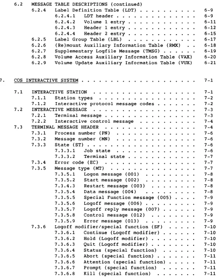
6.2 MESSAGE
6.2.4 6.2.5 6.2.6 6.2.7 6.2.8 6.2.9
TABLE DESCRIPTIONS (continued)
Label Definition Table (LOT)
·
· .
6.2.4.1 LOT header
.
. ·
·
· ·
· · ·
·
.
6.2.4.2 Volume 1 entry
·
·
·
·
6.2.4.3 Header 1 entry
·
· ·
·
6.2.4.4 Header 2 entry
·
· ·
·
·
Label Group Table (LBL)
· · ·
·
(Re)mount Auxiliary Information Table (RMX)
Supplementary Logfile Message (TMSG)
·
·
·
·
Volume Access Auxiliary Information Table (VAX)
Volume Update Auxiliary Information Table (VUX)
.
.
6-9 6-9 6-11 6-12 6-15 6-17 6-18 6-19 6-20 6-21COS INTERACTIVE SYSTEM . . . 7-1
7.1
7.2
7.3
INTERACTIVE STATION
7.1.1 Station types
7.1.2 Interactive protocol message codes.
INTERACTIVE MESSAGE . . . • .
7.2.1 Terminal message . . . .
7.2.2 Interactive control message
TERMINAL MESSAGE HEADER
7.3.1 Process number (PN) . • • . . • . .
7.3.2 Message number (MN)
7.3.3 State (ST) • . • . • • . • . •
7.3.3.1 Job state
7.3.4 7.3.5
7.3.6
7.3.3.2 Terminal state • . . . • •
Error code (EC) . . • . • . • . .
Message type (MT) • • • • • • • • • • • • •
7.3.5.1 Logon message (001) . . • . . . • . .
7.3.5.2 Start message (002)
7.3.4.3 Restart message (003)
7.3.5.4 Data message (004)
7.3.5.5 Special Function message (005)
7.3.5.6 Logoff message (006) . . •
7.3.5.7 Logoff reply message (007)
7.3.5.8 Control message (012)
7.3.5.9 Error message (013)
Logoff modifier/special function (SF)
7.3.6.1 Continue (Logoff modifier) .
7.3.6.2 Hold (Logoff modifier) • •
7.3.6.3 Quit (Logoff modifier) • .
7.3.6.4 Status (special function)
7.3.6.5 Abort (special function) • •
7.3.6.6 Attention (special function)
7.3.6.7 Prompt (special function) . • . •
7.3.6.8 Kill (special function) . • . •
7-1 7-2 7-2 7-3 7-3 7-4 7-4 7-6 7-6 7-6 7-6 7-7 7-7 7-7 7-8 7-8 7-8 7-8 7-9 7-9 7-9 7-9 7-9 7-10 7-10 7-10 7-10 7-10 7-11 7-11 7-11 7-11
[image:10.612.92.537.52.625.2]8.
7.3
7.4
7.5
TERMINAL MESSAGE HEADER (continued) 7 . 3 . 7 Mode flag . . . • . . . .
7.3.7.1 Buffered mode (0)
7.3.7.2 Unbuffered mode (1)
7.3.8 Chain flag (CHN) . . .
7.3.9 Format type (FT) • • . . . . • • .
7.3.10 Word count (WC) . . . .
TERMINAL MESSAGE TEXT
7.4.17.4.2
Logon, start, and restart text . Data and Logoff reply text . .
7.4.2.1 COS interactive blocked format . .
7.4.2.2 Restrictions on COS interactive
7.4.2.3
blocked format . . . Unblocked text . . .
7.4.3 Prompt special function text.
INTERACTIVE ERROR PROCESSING . . . .
7.5.1 Errors detected by the front end . . . • . .
7.5.2 Errors detected by the Cray computer system
STATION SLOT
8.1 8.2
USAGE
ORGANIZATION .
APPENDIX SECTION
A. UNICOS STATION CALL PROCESSOR (USCP) .
A.1 A.2 A.3 A.4 A.S A.6 A.7 A.8 A.9 A.10 A.11 A.12 A.13
USCP CONFIGURATIONS USCP FUNCTIONS . . . USCP MESSAGE CODES . INTERACTIVE SUPPORT
INTERACTIVE STATION SLOTS FILE TRANSFER . . . . UNICOS BATCH JOB PROCESSING BATCH JOB STATUS . . . .
'.
.
.
A.8.1 A.8.2 A.8.3 A.8.4
Job status . . . .
Dataset status . • . . . . Enter logfile request (015)
Statclass . . . .
A.8.S System status
OPERATOR COMMANDS USCP RESTRICTIONS
REQUIRED STATION CHANGES • ADDITIONAL MESSAGE TYPE (MT=14)
HYPERCHANNEL ACCESS IN A GOS ENVIRONMENT . .
A.14 ACCOUNTING ENHANCEMENTS
B. SCP ERROR RECOVERY
.
.
. .
.
. ·
B.1 ELIMINATION OF ERROR LCP GENERATION
. .
.
.
. .
B.2 IOS ERROR RECOVERY
.
.
.
.
. · .
B.2.1 Read operations/input LCPs
· .
B.2.2 Write operations/output LCPs
.
. . .
B.3 ERROR LCP PROTOCOL ENHANCEMENTS
C. MNEMONICS USED IN TABLES . . . • . . . .
FIGURES 1-1 1-2 1-3 1-4 2-1 2-2 3-1 3-2 3-3 4-1 7-1 A-1 A-2 A-3 A-4 A-5 A-6 A-7 B-1 B-2
Front-end Linkage to the Cray Computer System . • . . . .
Front-end Linkage to a Cray Computer System Through the IOS
Front-end Linkage Without an IOS . . . .
Front-end Linkage with an IOS • . . . • . . • . . • . .
Transmission Units . . . .
Transmission Units for the NSC HYPERchannel Network Adapter
Stream Control Byte Flow . . . .
Sender SCB State Diagram . . . . • . . . . .
Receiver SCB State Diagram . . . . . . . . . .
Message Code Flow . . . .
Interactive Message . . • . . . . .
USCP Configuration under UNICOS . . . .
USCP Configuration under GOS . . . .
USCP Program Flow . . . .
Interactive Access Connections File Transfer Process
Batch Connection for an Interactive User under UNICOS
Station/USCP/NQS Interaction . . . . . . . . .
Error Recovery Sequence, Case 1 . . • . .
Error Recovery Sequence, Case 2 . . . • . •
TABLES 3-1 3-2 3-3 4-1 4-2 4-3 4-4 4-5 4-6 4-7
Stream Control Bytes . . . • . . . .
Receiver SCB Response as a Function of Sender SCB . . . • . .
Sender SCB Response as a Function of Receiver SCB • . . .
Message Codes . . . • • . . • . • .
Dataset Header Field Usage . . . . .
SCP Message Error Codes . . . • . • . . FED Message Error Codes • • . . . • • . . Unsolicited Operator Reply Message Codes
Operator Functions . . . • . . .
Debug Function Request Field Usage
B-1 B-1 B-1 B-1 B-1 B-2 C-1 1-1 1-1 1-2 1-2 2-2 2-2 3-5 3-10 3-11 4-4 7-3 A-1 A-2 A-2 A-6 A-9 A-10 A-12 B-3 B-4 3-2 3-8 3-9 4-2 4-16 4-19 4-22 4-31 4-40 4-44
TABLES (continued)
7-1
7-2
7-3INDEX
Interactive Protocol Message Codes . . . • .
Terminal Message Types . .
. . • • . . . • . . . .
Cray Computer System Error CodesSM-0042 E
7-2 7 -7
7-18
COS 1.16/UNICOS 3.0 Enhancements
The 1.16 release of COS includes several enhancements of and additions to
previous versions of the operating system. Those enhancements that
affect the Front-end Protocol Manual are presented in this description.
The major enhancement affecting the manual were several features being added to the Station Call Processor (SCP):
• Variable segment support for FEI connections - Allows stations to
receive only the meaningful part of a segment. this is defined by
the segment bit count.
• Station operator support - Allows a station to define a password
to be associated with a station user who has the ability to issue
operator commands on the behalf of the station to SCPo The
password is sent to SCP at logon time in the logon segment.
• Group 10 Feature - Allows for a group of stations to be viewed as
a single entity. Commands issued to SCP are evaluated as a
group. The first character (the major letter) associates a set of
stations as a groupi the second character (the minor letter) uniquely identifies a station group.
• Forced Segment Transfers - This reduces the number of 1/0 requests
made by stations to the host system, thereby improving system
performance. This feature must be requested when the stations
logs on.
Variable segments, operator station, and forced segment transfers are all
features that have to be enabled by a station. Use of the group 10
feature may require that a station change its 10 to match the group 10.
Other enhancements to the Front-end Protocol Manual include Fast
Secondary Storage (FSS) Preemption and N-packet Driver. The FSS feature
provides the ability to overscribe FSS devices that are configured as
generic resources. Station segments for the RSTAT display and for
Operator Requests are altered in such a way that all stations will continue to work without modification.
The design of the N-packet driver allows for the implementation of a
protocol-independent interface to the NSC A130 HYPERchannel adapter. The
design allows the protocols for SCP interface and the non-SCP (protocol-independent) interface to share a single A130 adapter. Enhanced error recovery was also added for SCPo
The 3.0 release UNICOS includes support for the UNICOS Station Call
Processor, described in Appendix A of this manual. In addition, USCP
I
I
I
INTRODUCTION
This manual describes the communications protocol required for
communication between the Cray operating system COS and any front-end
computer system. Appendix A describes the communications protocol for
communication between the Cray operating system UNICOS and a front-end system.
Communication between the front-end system and the Cray computer system
is through a front-end interface (FEI). This 6-Mbyte/s channel can be
connected directly to the Cray mainframe (figure 1-1), or, for a system with an I/O Subsystem (IDS), the channel can be connected to the IDS
(figure 1-2).
Front-end
Cray Channel Front-end
Mainframe Coupler Computer
(FEI)
Figure 1-1. Front-end Linkage to the Cray Computer System
Front-end
Cray IDS Channel Front-end
Mainframe Coupler Computer
(FEI)
Figure 1-2. Front-end Linkage to a Cray Computer
System Through the IDS
Any Cray mainframe can be connected to front-end computers through the
Network Systems Corporation (NSC) HYPERchannel network. This network
connects to the Cray mainframe either directly (figure 1-3) or through the IDS (figure 1-4), by means of the NSC A130 network adapter.
1
Cray Mainframe
NSC HYPERchannel
Front-end Computer
Figure 1-3. Front-end Linkage Without an IDS
Cray Mainframe
NSC HYPERchannel
Front-end Computer
Figure 1-4. Front-end Linkage with an IDS
The protocol is the same for each front-end configuration. The COS task
that handles communication at the Cray mainframe is the Station Call
Processor (SCP). The front-end interface is transparent to the SCPo For
a complete discussion of the SCP and its processing flow, see the COS
Internal Reference Manual, Volume III: CSP.
The UNICOS Station Call Processor (USCP) is a privileged user job that
handles communication with the front end. See appendix A for a complete
description of USCP.
A front-end system initiates communication with the Cray mainframe, after the channel is turned on, by sending i t a message; the mainframe
interprets the message and returns a message. (Both messages contain control information and, possibly, data.) The message sent by the Cray mainframe can be based on previously received information or can be developed by a COS operation.
GENERAL PROTOCOL
2
2.1 TRANSMISSION
The front-end system communicates with the Cray mainframe over a Cray 1/0
channel pair. Each input or output operation is termed a
transmission.
The maximum data in one transmission is determined by buffer sizes at the front-end system.
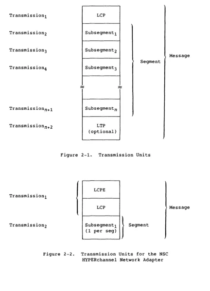
A single transmission (figure 2-1) can be anyone of the following:
• A set of control information called a
link control package
(LCP)• A unit of data called a
subsegment
• An optional set of checksum information called a
link trailer
package
(LTP)For the HYPERchannel network, a single transmission (figure 2-2) can be one of the following:
• A set of control information called a
message
proper,
consistingof the
link control package extension
(LCPE) and the LCP• A unit of data called a
segment
2.2 MESSAGE
A
message
is a group of related transmissions sent in the samedirection.
At logon, a front-end system adopts a message protocol that is either
checksummed or non-checksummed. Under checksummed protocol, a message
must include at least an LCP and an LTP. (This minimum does not apply to
logon.) Under non-checksummed protocol, a message can be simply an LCP,
or an LCP followed by one or more subsegment data transmissions in the same direction.
When the NSC HYPERchannel network is in use, checksumming is unnecessary
because the hardware detects and corrects errors. Therefore, only
Transmission1
Transmission2
Transmission3
Transmission4
Transmission n +1
Transmission n+2
Transmission1
Transmission2
LCP
Subsegment 1
Subsegment2
Subsegment 3
Subsegment n
LTP (optional)
Segment
--Figure 2-1. Transmission Units
LCPE
LCP
Subsegment 1
I
Segment(1 per seg)
Figure 2-2. Transmission Units for the NSC
HYPERchannel Network Adapter
Message
Message
[image:22.613.92.524.81.680.2]An entire message is sent in one direction. The computer receiving the message waits for the complete message before sending its own message in
the opposite direction. This procedure is called two-way alternate
protocol;
i t is also calledhalf-duplex protocol
because data travels in one direction at a time.A segment is the group of one or more data subsegments in a single
message. The station specifies the subsegment size and number of
subsegments per segment in the Logon segment. For example, a segment can
be set to the size of a disk unit track.
A logon option allows a station to send and receive variable length
segments. A second option allows a station to request forced segment
transmission from COS. This option results in an LCP and segment
transmission for each outgoing message. This reduces the number of I/O
requests made by stations to COS, thus improving system performance. Both options are specified in the logon segment.
COS concurrently processes a number of datasets, commands, and responses
by interleaving messages associated with them. Messages for one dataset
are interleaved with messages for other datasets and with messages unrelated to datasets.
2.3 STREAM
A stream is a software path that includes all messages related to a
single dataset. Each stream is identified by a stream number. The
number of streams is determined by front-end parameters, with a maximum
of eight streams for either input or output. Thus, in communication
protocol, each channel is logically divided into a maximum of 16
unidirectional paths. Interleaved datasets pass concurrently between two
computers over these paths.
The terms
input
andoutput
are used relative to the Cray mainframe;an input stream is the flow of data from a front-end system to the Cray mainframe, and an output stream is the flow from the Cray mainframe to a
front end. The front end sets the maximum number of input and output
streams at logon. Among the factors influencing the maximum setting is
the amount of table space allotted by the site on the front end and in central memory; the space allotment is influenced in turn by the
station's resources and transfer requirements.
The sender assigns a stream by notifying the receiver of its readiness to
send on that stream. The stream is not active (no messages are allocated
to it) until the receiver replies that i t is ready to receive on that
stream. The stream remains active until the receiver receives all of the
Messages are not allocated to unassigned or inactive streams.
Operational request and response messages do not require a stream for
transmission. However, only one operational request can be outstanding
from the front-end station for each logged-on station.
2.4 SEGMENT
A
segment
comprises the data in one message. It is preceded by anLCP. All datasets are transmitted in segments (figure 2-1). At the
driver level, a segment is broken into
subsegments
for separatetransmission across the interface. When communication is initiated, the
maximum number of subsegments per segment is specified by the front-end
system. The HYPERchannel network allows only one subsegment per segment.
The maximum size of a segment is an integer multiple of the size of a
subsegment; both sizes are specified in the Logon message. The Logon and
Start messages have a fixed segment size of 6 words; section 4 discusses these messages.
2.5 SUBSEGMENT
A
subsegment
is a block of data that is part of a segment and is the largest amount of data transmitted across the interface at the driverlevel. Only the first subsegment of a segment is preceded by the LCP.
The number of 64-bit words in a subsegment is specified by the front-end
system at initiation of communications. This size must conform to the
word boundaries of the front-end system and the Cray mainframe. For
example, to meet the boundary requirement for the CDC 7600 computer system, the size must be a multiple of 960 (fifteen 64-bit words or sixteen 60-bit words).
The complete subsegment length is transmitted, even if only a portion of
i t is valid data. The segment bit count (SGBC field) in the LCP
distinguishes the valid data from the fill bits in the last subsegment. The transmission length must be constant to allow length checks, which
are a means of detecting hardware errors. If the Variable Segment Size
Transfer Enable (VARS) flag is set in the Logon segment, however, the transmission length is represented by the segment bit count rounded up to the next multiple of 64 bits; in this case, the driver checks for
hardware transmission errors.
2.6 LINK CONTROL PACKAGE (LCP)
The LCP consists of six 64-bit words preceding the first subsegrnent of a
segment. When no data follows the LCP (null segment) and
non-checksumming protocol is used, the transmitted message includes only
the LCP. In the case of a null segment and checksummed protocol, an LTP
follows the LCP. Any unused fields (shown in the following table by
slashed lines) contain D's.
A 2-character destination identifier (DID) identifies the message receiver; a 2-character source identifier (SID) identifies the message sender.
If the installation parameter I@GROUP (see the COS Operational Procedures Reference Manual) is turned on, the first character of the DID or SID is
referred to as the station's major letter. The second character of the
DID or SID is referred to as the the station's minor letter. Stations
which are I@GROUP-enabled can be viewed as a logical entity. This entity
then has the privileges associated with a single station.
The NSSG field holds a count of the subsegments in the segment to
follow. This field is zeroed when there are no subsegments. The
HYPERchannel network allows only one subsegment per segment. The SGBC
field specifies the number of valid data bits in the segment.
The message number (MN) field contains a modulo 256 number assigned to
the message by the sender. The Logon message from the front-end system
and the responding Start message from the Cray mainframe are always
numbered 1. The sender forms the current message number by incrementing
the number of its previous message by 1. A Message Error message uses
the expected message number of the message in error and does not increment the number.
COS sets the Request Pending flag (RQP) when station messages are queued
to be sent. The RQP flag is needed because certain front-end messages,
such as operator function requests and display requests, require SCP to
reply with the requested message, and no other. If a station is sending
these requests continually, they block the transmission of a Station
Message (MC=46) by SCPo The RQP flag requests the station not to send
operator requests to SCPo When COS receives an LCP not requiring a
response, SCP sends the queued station messages. The stream control
bytes (SCBs) should be specified in the station message LCP. (See
section 3 for a description of SCBs.)
The stream number (STN) field is an ordinal specifying a particular data
stream. This field is used for message codes dealing with data
transmissions; for other operations, the field contains D's. Input and
The segment number (SGN) field is the ordinal of the data segment for
this message. This field is used only for data messages; for other
operations, the field contains O's.
Field DID SID NSSG MN MC MSC RQP STN SGN SGBC ISCBm OSCBn 2-6
o
8 16 24 32 40 48 56 6301 DID SID NSSG MN MC MSC
11 1//1 STNI SGN SGBC
2 1 / / / / / / / / / / / / / / / / / / / / / / / / / / / / / / / / / / / / / / / / / / / / / / / / / / / / / / / / / / / / / / / / / 1
31 ISCB1 41 OSCB1
ISCB3 OSCB3 ISCB5 OSCB5 ISCB8 OSCB8 5 1 / / / / / / / / / / / / / / / / / / / / / / / / / / / / / / / / / / / / / / / / / / / / / / / / / / / / / / / / / / / / / / / / / 1
Word
o
o
o
o
o
o
1 1 1 1 3 4 Bits 0-15 16-31 32-39 40-47 48-55 56-63o
4-7 8-31 32-63 DescriptionDestination mainframe identifier; 2 ASCII alphanumeric characters.
Source mainframe identifier; 2 ASCII alphanumeric characters.
Number of subsegments in segment (O-n)
Message number (0-255)
Message code (see section 4)
Message subcode (see section 4)
Request Pending flag. Station
messages are queued by COS and sent
on receipt of any message not requiring a response, such as a
control message. See preceding text
for additional information.
Stream number (1-8)
Segment number (O-total number of segments)
Number of data bits in segment
0-7, Input stream m control byte
8-15,etc. (stream ordinal m+8)
0-7, Output stream n control byte
8-15,etc. (stream ordinal n+8)
I
2.7 LINK CONTROL PACKAGE EXTENSION (LCPE)
The LCPE controls the NSC HYPERchannel network adapter; i t is used only
on channels configured with these adapters. The LCPE consists of two
64-bit words preceding the LCP. The 8 words of the LCPE and LCP taken
together comprise the network message header (the message proper). Any
unused fields (shown in the following table by slashed lines) contain O's.
The 8-bit trunk control (TC) field selects all available trunks.
The Exception Message (EM) flag is not used in processor-to-processor communications.
Burst mode (BM) is not selected; the trunk operates in multiplex mode, which allows two or more messages to be transmitted at the same time.
The Associated Data (AD) flag is set when a data segment accompanies the message proper.
The access code (AC) is disabled; therefore, any destination adapter that is physically addressable can be accessed.
When the Cray mainframe receives an input message, the source unit number is placed in the destination unit number (DN) field for the return
message to the front-end system.
When the front-end system receives a message, the source unit number (SN) is placed in the DN field for the return message to the Cray mainframe.
o
8 16 24 32 40 48 56 6301
TC1/ / / /1111
AC DN SN ---1 ---1 / / / / / / / / / / / / / / / / / / / / / / / / / / / / / / / / / / / / / / / / / / / / / / / / / / / / / / / / / / / / / / / / / ---1Field Bits Description
TC 0-7 Trunk control
EM 13 Exception Message flag (unused)
BM 14 Burst Mode flag (unused)
AD 15 Associated Data flag
AC 16-31 Access code (unused)
DN 32-47 Destination address
2.8 LINK TRAILER PACKAGE (LTP)
The link trailer package (LTP) contains the checksum when checksummed protocol is used, and appears only under checksummed protocol. (The LTP and checksummed protocol are not supported over the HYPERchannel
network.) In checksummed mode, the Start message and all subsequent messages must have an LTP. The following do not use LTPs:
• The logon LCP and segment
• A message error response to an invalid Logon message
The LTP consists of three 64-bit words that follow the last subsegment or the LCP if there are no subsegments.
o
63o
I
ONES---11
ZERO---21
CHECKSUMTo request LCP and segment checksumming, set the checksum size field of the Logon segment to a nonzero value at logon time. The allowed sizes are 64, 32, 16, and 8.
The checksum algorithm is as follows:
1. Clear the checksum accumulator.
2. Exclusive OR (XOR) the next 64 bits of message with the accumulator; repeat until the entire message is processed.
3. Reduce the checksum by XOR of the upper half of the checksum with the lower half until the desired width is obtained.
2.9 OPTIONAL HYPERCHANNEL SUPPORT
The Cray mainframe can support the HYPERchannel local network in addition to or instead of the standard Cray channel coupler. The HYPERchannel network offers the following features:
2-8
• Connections to many other computer systems
• Multidrop capability on a single trunk
• Connection to other HYPERchannel local networks through the NSC communications adapters
I
In the implementation of the HYPERchannel, one or more NSC A130 network
adapters are connected to the Cray mainframe through 1/0 channels on the
mainframe or the lOS.
COS protocol is used with the following restrictions.
• LTPs are not supported.
• Only one data subsegment per segment is allowed.
• Restart messages are not supported.
The UNICOS Station Call Processor (USCP) can communicate with a front-end
station through either the NSC HYPERchannel or the FEI. See appendix A
I
DATA FLOW ACROSS THE INTERFACE
3.1 STREAM CONTROL BYTE (SCB)
A
stream control byte
(SCB) is an 8-bit octal code associated with eachinput stream and each output stream, indicating one of the following:
• The status of the stream
• A request to the other computer to take action on that stream
• A response to a request on that stream
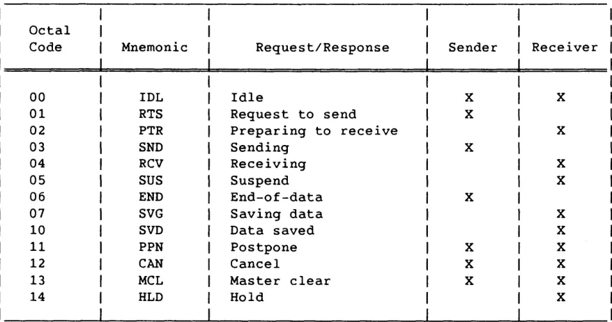
The SCBs (table 3-1) for all defined streams are included in every Link
Control Package (LCP). SCBs are meaningful for every message in a
defined stream, but they are ignored for undefined streams. The defined
input and output streams include streams 1 through the maximum number of input and output streams, respectively, as defined in the Start message (or no defined streams if the maximum is 0).
In the following descriptions of SCBs, the input and output stream
designations are relative to the sender. For example, if the front end
assigns output stream 3 for staging a dataset to the Cray mainframe, messages from the front-end station to COS use the SCB for output stream
3 and messages from COS to the station use the SCB for input stream 3. See appendix A for a discussion of UNICOS Station Call Processor (USCP) data flow.
3.1.1 IDLE (IDL=O)
An IDL SCB indicates an inactive and available stream.
3.1.2 REQUEST TO SEND (RTS=l)
RTS from the sender indicates readiness to initiate a data transfer. RTS from the receiver is invalid.
Table 3-1. Stream Control Bytes
Octal
Code Mnemonic Request/Response Sender Receiver
00 IDL Idle X X
01 RTS Request to send X
02 PTR Preparing to receive X
03 SND Sending X
04 RCV Receiving X
05 SUS Suspend X
06 END End-of-data X
07 SVG Saving data X
10 SVD Data saved X
11 PPN Postpone X X
12 CAN Cancel X X
13 MCL Master clear X X
14 HLD Hold X
3.1.3 PREPARING TO RECEIVE (PTR=2)
PTR is the normal response to RTS. PTR indicates that the receiver can
accept the initiation of a data transfer but cannot currently begin to
receive. PTR from the sender is invalid.
3.1.4 SENDING (SND=3)
SND, from the sender, indicates that a data transfer is initiated and is
in progress. SND is invalid from the receiver.
3.1.5 RECEIVING (RCV=4)
RCV, from the receiver, indicates that a data transfer is initiated and
is in progress. RCV is invalid from the sender.
[image:32.612.88.527.76.307.2]3.1.6 SUSPEND (SUS=5)
The receiver temporarily stops data transfer on the stream marked SUS.
The receiver signals the end of suspension by returning an RCV
sca
on thesame stream. By not sending, the sender implicitly suspends the
transfer; therefore, the sender does not need to use SUS.
3.1.7 END DATASET (END=6)
The sender uses END to signal the end of the data transfer. END may
accompany the last segment of the data transfer, or i t may be sent on a
subsequent message. END is invalid from the receiver.
3.1.8 SAVING DATASET (SVG=7)
The receiver uses SVG to notify the sender that the data transfer is
being saved. SVG is invalid from the sender.
3.1.9 DATASET SAVED (SVD=10)
The receiver uses SVD to notify the sender that data transfer is complete
and the data has been saved. SVD is invalid from the sender.
3.1.10 POSTPONE (PPN=ll)
The sender uses PPN to request that the receiver delete all data received
so far; the sender will retransmit. The receiver uses PPN to request the
abnormal termination of a data transfer or a stream assignment. The
receiver deletes the partial dataset received; the sender should retransmit.
3.1.11 CANCEL (CAN=12)
The sender uses CAN to request that the receiver delete all data received so far; the data will not be retransmitted, and the job requesting the
data transfer (if there is one) will be dropped. The receiver uses CAN
3.1.12 MASTER CLEAR (MCL=13)
Either the sender or the receiver may issue MCL. MCL can be issued at
any time to indicate an irreconcilable error condition on a specific
stream. MCL has the effect of an immediate PPN.
3.1.13 HOLD (HLD=14)
The receiver issues HLD when i t encounters an exception condition for a
data transfer requiring operator intervention. One example of such a
condition is when the disk is full. The sender does not attempt to send
the dataset again until the hold condition has been cleared by the
operator. For a data transfer from COS, a Release Held Job (RL) operator
function request for the file clears the HOLD condition (see section 4). HLD may not be used by the sender.
3.2 STREAM CONTROL BYTE FLOW
The sending computer reserves a stream before transmitting a dataset. A
dataset sent by the front end contains one of the following:
• An input job destined for processing on the Cray mainframe
• Associated job data to be maintained on mass storage, originating
from a front-end peripheral device
• Data destined for mass storage and not associated with a job
A dataset sent by the Cray mainframe to the front end consists of output from a Cray mainframe job, such as data to be printed, punched, or
plotted. Regardless of the sender, all data is treated the same at the
driver and interface levels.
Sending a dataset
is
a decision of the sender (as when the front endsends an input job dataset to the Cray mainframe) or is a response to an
earlier request for a dataset sent by the other computer. In either
case, a higher-level system routine requests the driver to send data.
Figure 3-1 shows the sequence of SCBs. The diagram flows down. The
following paragraphs describe the sequence.
A free stream at the interface level requires acceptance of the request
to send data. The receiver uses IDL SCBs to indicate which streams are
idle. The sender assigns a stream by entering an RTS in the stream's SCB
in the next LCP (point C in the figure). The message is otherwise
unrelated to this stream. Interleaving allows the next message to
contain data for a different dataset sent on another stream.
Sender
PPN
IDL
RTS
Receiver
IDL
RCV SUS
IDL
Figure 3-1. Stream Control Byte Flow
[image:35.613.96.499.64.618.2]In response to the RTS, the receiver can do the following:
• Abort the RTS by replying with a PPN
sca
for that stream• Acknowledge the sender's RTS by responding with a PTR
sca
withoutactually being able to receive data
• Acknowledge the request by replying with RCV or SUS when its
conditions and resources are available (point D in figure 3-1)
On receiving the RCV or SUS reply, the sender immediately leaves the RTS
state. If the sender has data to send, the
sca
is changed to SND forsending. When data is available and sent with a message, the segment
information in the LCP is set for the stream, and the segment itself
contains data associated with the dataset. The first segment sent
(segment 0) contains dataset header information. This information
includes the name of the dataset, the disposition code, the terminal
identifier, format information, dataset size, and so on. Subsequent
segments contain the data in the dataset. See section 4, code 6 (dataset
header message).
After the initial segment transmission, the receiver performs overhead functions; these include assigning buffer space and delaying transmission
by replying with SUS. When the receiver is ready to accept data sent on
the stream, i t issues RCV. The receiver can suspend at any time, but the
normal flow is in the SND/RCV exchange.
Three additional options are available to the receiver. With the first
option, a receiver requests a postponement by issuing PPN to inform the sender of a temporarily irrecoverable situation and discards the partial
dataset already received. The sender replies to PPN with IDL and later
reinitiates the dataset transmission. With the second option, the
receiver cancels by issuing CAN, which resembles PPN except that i t
deletes the dataset with no option for retransmission. With the third
option, if the receiver is the front end, i t can request that the dataset be held pending operator action by issuing an HLD SCB, in which case the sender replies with IDL.
During the SND/RCV process, the sender also has three other
sca
options.With the first option, the sender cancels (CAN) to direct the receiver to delete the partial dataset already received, drop the job that requested the dataset (on an ACQUIRE or FETCH to COS), and return the stream to IDL.
With the second option, the sender issues a postpone (PPN) to inform the receiver to delete the partial dataset already received and return the
stream to IDL. The sender decides whether the cancellation is temporary
or permanent. The postpone function is used when a transfer can be tried
again; the cancel function specifies that there will be no subsequent tries.
I
With the third option, the sender indicates end-of-data transfer on the
stream (END) (point E in figure 3-1). In response, the receiver normally
performs the overhead chores required to preserve the dataset, and
responds with
SVG
until that activity is complete. When disposition ofthe dataset is complete, the receiver responds with SVD. However, after
any number of
END/SVG
exchanges, and before dataset disposition iscomplete, the receiver can cancel or postpone, with the implications
previously described. The sender acknowledges
SVD, PPN,
orCAN
byreturning the stream to IDL. The receiver replies with IDL; the
transmission is complete, and the stream is free.
MCL is the only stream status that is issued by either sender or receiver at any time and indicates at any stage of communications that an
irrecoverable error has occurred. MCL requires immediate termination of
data transfer on the stream. The other computer is expected to respond
to MCL with IDL.
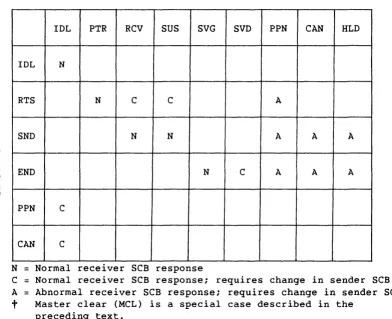
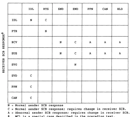
Tables 3-2 and 3-3 summarize the response SCBs for the sender and receiver.
Errors are indicated in the LCP message code rather than on a stream
basis. See the description of the Message Error code (012) in section
4. No segment is associated with a Message Error LCP, and the SCBs in
this LCP are ignored. The sender has the option to repeat the message
3-8
Table 3-2. Receiver SCB Response as a Function of Sender SCB
RECEIVER SCB RESPONSEt
IDL PTR RCV SUS SVG SVD PPN CAN HLD
IDL N
RTS N C C A
SND N N A A A
END N C A A A
PPN C
CAN C
N
=
Normal receiver SCB responseC
=
Normal receiver SCB response; requires change in sender SCB. A=
Abnormal receiver SCB response; requires change in sender SCB.t
Master clear (MCL) is a special case described in the preceding text. [image:38.613.114.506.109.428.2]I
Table 3-3. Sender
sea
Response as a Function of Receiversea
SENDER
sea
RESPONSEtIDL RTS SND END PPN CAN HLD
IDL N C
PTR N
+-r:LI
Ul
Z
0
0.. RCV N C A A A
Ul r:LI
~
CIl
U SUS N C A A A
Ul
~
rzl :>
H SVG N
r:LI
U
r:LI IJr:i
SVD C
PPN C
CAN C
N
=
Normal sender SCB responseC
=Normal sender
SeB response; requires change in receiver SeB.
A
=
Abnormal sender SCB response; requires change in receiver SCB.t
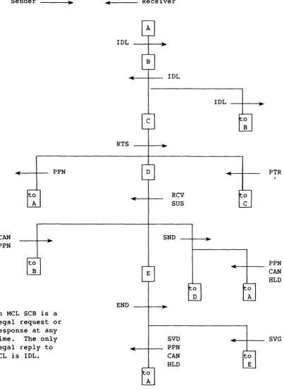
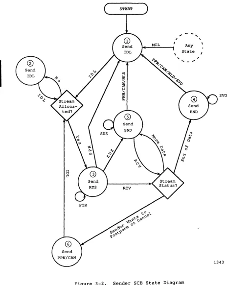
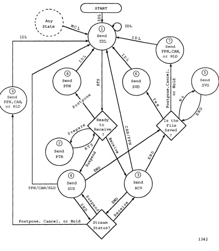
MCL is a special case described in the preceding text.Figures 3-2 and 3-3 show the possible exchange of SBCs between the sender
and the receiver. Arrows represent state transitions. Circles represent
possible sender states and the actions taken when in those states. Two
types of possible actions are as follows:
• Send an SCB
• Make a decision about the stream
In figure 3-2, if the sender has sent an SCB, the possible state
transitions correspond to SCBs received on the stream. If the sender
made a decision about the stream, the transitions correspond to possible
ontcomes. Figure 3-3 shows the corresponding actions for the receiving
side.
[image:39.612.100.520.108.486.2]START
,
-
...
,
,
,
MeL I Any \ State I
I
~.A,
,
~-
' - "
0~
Q -~
~ ~a
::z::
"- -~
~ ~
u
"-Z
Q. SVG
Q.
Figure 3-2. Sender SeB State Diagram
[image:40.617.55.520.64.646.2],
...
,...
,
,
I
I
Any
,
\State
\
,
"
.,
IDL ' - -...
~
Q) C)
Ul s:: '0
8 to r l
~ U 0
:x:
s....
0
PPN/CAN/HLD
Postpone, Cancel, or Hold
1342
[image:41.612.90.531.67.574.2]I
MESSAGE CODES
A message code identifies a message on the communication link, sent by
either the front-end station or COS. The message can have one of the
following functions:
• Initialize, shut down, resynchronize, or recover the link
• Specify the initiation and transfer of datasets
4
• Request or reply with status for a dataset transfer, a job, or COS
• Exercise control over COS, jobs, and dataset transfers
The message code occupies an 8-bit field in the link control package
(LCP). Certain codes indicate the existence and content of an associated
data segment. A stream and segment are required for certain message
codes related to data transfer. One group, the synchronous message
codes, can be distinguished from the other message codes. The
synchronous request codes are generally processed immediately; the return
message to the front end is the message reply. If i t is not possible to
reply immediately, or a higher-priority message (such as a dataset transfer request or a station message) preempts the reply, the Station
Call Processor (SCP) returns the highest-priority message available. The
reply to the synchronous request is made when the request is processed and no higher priority messages are queued.
SCP permits only one synchronous request to be outstanding at any time. If a synchronous request is received while a previous synchronous request
is being processed, SCP replies immediately with a message error. All
other message types are processed normally under this condition. Table
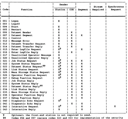
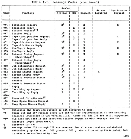
4-1 summarizes the message codes. See appendix A for a list of the
I
Code 001 003 004 005 006 007 011 012 013 014 015 016 017 020 021 022 023 024 025 026 027 031 032 033 034 035 036 037 040 041 042 043Table 4-1. Message Codes
Function
Logon Logoff Start Restart Dataset Header Dataset Segment Control
Message Error
Dataset Transfer Request Dataset Transfer Reply Enter Logfile Request Enter Logfile Reply
Unsolicited Operator Message Unsolicited Operator Reply Job Status Request
System Status Request Dataset Status Requesttt Link Status Request
Mass Storage Status Request Operator Function Request Debug Function Request Job Status Reply System Status Reply Dataset Status Replytt Link Status Reply
Mass Storage Status Reply Operator Function Reply Debug Function Reply Diagnostic Echo Request Diagnostic Echo Reply Interactive Request Interactive Reply
Sender Station x
x
X X X X X X Xxt
X X Xxt
xt
xt
xt
xt
xt
xt
xt
xt
X COS X X X X X X X X X X X X X X X X X X X X X X Segment X X X X X X X X X X X X X X X X X X X t Optional; the front-end station is not equired to send.Stream Required
Synchronous Request
X
tt Codes 056 and 057 replace codes 023 and 033 for implementation of the security features introduced in COS version 1.12. Codes 023 and 033 are still supported.
1103
[image:44.612.89.518.70.471.2]I
I
I
I
Table 4-1.
Code Function
044 Statclass Request 045 State lass Reply 046 Station Messagettt 047 Station Reply
050 Tape Configuration Request 051 Tape Configuration Reply 052 Tape Job Status Request 053 Tape Job Status Reply 054 Configure Request 055 Configure Reply 056 Dataset Status Request
(Ownership)tt 057 Dataset Status Reply
(Ownership)tt
060 Job Information Request 061 Job Information Reply 062 Stream Status Request 063 Stream Status Reply 064 Generic Resource Status
Request 065 066 067 070-077 100 101
Generic Resource Status Reply
Task Display Request Task Display Reply
Reserved for site use~~ Swap Space Status Request Swap Space Status Reply
Message Codes (continued)
Sender Station COS
xt
xt
x
X
xt
Xxt
xt
xt
X X X X X X X X X X Segment X X X X X X X X X X X X X X X X Stream Required Xt
Optional; the front-end station is not required to send.Synchronous Request X X X X X
tt
Codes 056 and 057 replace codes 023 and 033 for implementation of the security features introduced in COS version 1.12. Codes 023 and 033 are still supported.ttt
COS does not send if the front-end station logged on with message receive disabled (Logon field MRE=O).~ Reserved for CRI
"" Message codes 070 through 077 are reserved for site use, and are maintained exclusively by the site. COS prevents COS products from using these codes, but is otherwise unaffected by them.
[image:45.612.95.524.60.516.2]Figure 4-1 illustrates the order of message codes. The flow of the diagram
is downward. Notice that front-end station actions alternate with COS
actions.
Front End
Logon
Logon
Other message codes allowed for front-end station
A diagnostic echo request requires
immediate transmission of a diagnostic echo reply.
Restart
Start
Logoff
Other message codes allowed for COS
Figure 4-1. Message Code Flow
cos
Control
[image:46.613.107.503.112.666.2]