STABILITY CONTROL FOR SIX-WHEEL DRIVE
ARTICULATED VEHICLE BASED ON DIRECT YAW
MOMENT CONTROL METHOD
1YITING KANG, 2WENMING ZHANG
1
Doctoral Candidate, School of Mechanical Engineering, University of Science and Technology Beijing, CHINA
2Professor, School of Mechanical Engineering, University of Science and Technology Beijing, CHINA
E-mail: [email protected], [email protected]
ABSTRACT
Six-wheel drive (6WD) articulated dump truck has excellent passing ability and high productivity, but its stability should be improved. A dynamic model of 6WD articulated vehicle with 3 degree-of-freedom (DOF) is established. With the control variables of yaw velocity and side-slip angle at mass center of front body, a feedfoward-feedback control system is designed by linear quadratic regulator (LQR) theory based on direct yaw-moment control (DYC) method. A simulation with a step input of articulated angle is conducted, and the result shows that the value of side-slip angle at mass center, yaw velocity and lateral acceleration all drop after control, and the control system is effective to improve the vehicle stability. The weight coefficients are regulated to analyze their influence on control effect, and the result indicates that it is necessary to regulate them to reach the optimum of both energy and error of control.
Keywords: Articulated Vehicle, Vehicle Stability Control, Direct Yaw Moment Control (DYC), Linear
Quadratic Regulator (LQR)
1. INTRODUCTION
Articulated dump truck is a kind of off-highway vehicle with an articulated body, which allows front body rotate independently relative to rear body. Articulated dump truck is a 6x6 drive vehicle with 3 drive axles [1, 2]. Its steering angle and pitch angle reach 45° and 15° respectively, which can ensure that all tires contact ground simultaneously, so it has good passing ability and high productivity. In spite of the advantages mentioned above, the lateral and longitudinal stability of articulated dump truck get worse because of the increase of vehicle DOF, so its stability should be improved. Increasing the friction of articulated body and regulating the damping of steering hydraulic cylinder are the conventional methods to improve the vehicle stability, but these methods waste too much energy and have low reliability. With the development of control technology, DYC is applied in controlling vehicle stability. DYC is to change longitudinal forces on left and right wheels to generate an additional yaw moment to improve vehicle stability [3].
The direct yaw moment control using in wheel-motors and the active front steering (AFS) control algorithm are described in Ref.4, and the combination of DYC control and AFS control is researched in [5, 6]. Feedforward-feedback control is used to enhance the stability of a 4WD vehicle, and the feedback coefficient is decided by optimal control theory in [7]. A fuzzy feedforward-feedback control system is designed and tested with ABS to enhance the lateral stability of vehicle in [8], and a feedback control system based on H∞ theory is studied in [9]. Massto Abe and Ossama Mokhiamar [10-13] have researched and developed a DYC control system based on slip mode control method, and the system has been tested on real vehicle and proved to be effective.
In order to enhance the stability of 6WD articulated vehicle, a 3-DOF dynamic model of 6WD articulated vehicle is firstly established. Moreover, a feedforward-feedback control system based on LQR theory is designed. In order to verify the effectiveness of the control system, a simulation with a step input of articulated angle is conducted, and the weight coefficients are regulated to analyze their influence on control effect.
2. DYNAMIC MODEL
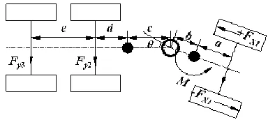
In order to study the dynamic character of articulated vehicle, the vehicle model is simplified to a system with 3 DOF, which includes rotations of front body and rear body along vertical axis, and the lateral translation of vehicle (Fig.1).
Figure 1. 3 DOF model of a 6WD articulated vehicle
The mass and rotational inertia of front and rear body are m1, J1 and m2, J2. The side-slip angles of
front, middle and rear tires are respectively α1, α2,
and α3. Lateral velocity of front body is v, and
articulated angle between front and rear body under steering is θ.
Firstly, two components of the absolute acceleration at mass center of front body are decided. As shown in Fig.2, XY is the absolute coordinate system, and xy is the vehicle coordinate system fixed on the front body. The x-component and y-component of the velocity at mass center of front body are respectively u and v at t. When the vehicle is steering, its motion includes translation and rotation, so both value and direction of the velocity at mass center of front body have changed at t+△t. The directions of horizontal axis and vertical axis in the vehicle coordinate system also have changed at the same time.
Variation of velocity along axis y is
1 ( ) cos ( )sin
y
V v v
φ
v u uφ
∆ = + ∆ ∆ − + + ∆ ∆ (1)
φ
∆ is very small, and the small quantity in the second order is ignored. Eq.1 is transformed to
1
y
V v u
φ
∆ = ∆ + ∆ (2)
Figure 2. Motion analysis based on the coordinate system fixed on the vehicle
Yaw velocity of front body is ω. Eq.2 is divided by ∆t and then taken to the limit. The y-component
of absolute acceleration at mass center of front body in the vehicle coordinate system is
ay1 = +v& uω=uβ&+uω (3)
Similarly, the variation of y-component of absolute acceleration at mass center of rear body in the vehicle coordinate system is
ay2 = +v& uω− +(b c)ω&+cθ&& (4)
Equilibrium equations of force and moment of the vehicle are
1 1 2 2 1 2 3
1 2 2 1 2 3
2( ) 2 2 ( ) 2 ( ) 3
y y y y y
y y y y
y y y
m a m a F F F
J m a b aF bF bF
J m a c c d F c d e F
ω θ ω
+ = + +
− = − −
− + = + + + +
& && &
(5
)
There is a linear relationship between side-slip angle and lateral force when side-slip angle is relatively small. The articulated dump truck always travels in a low speed, and the side-slip angle of tire is generally no more than 3°. So the lateral force and side-slip angle are considered to satisfy the linear relationship:
Fy =k
α
(6)where k is cornering stiffness, and α is side-slip angle of tire.
1 2 3 ( ) ( ) ( ) ( ) a u
b c d c d
u
b c d e c d e
u ω
α β
ω θ
α θ β
ω θ
α θ β
= − − + + − + = − − + + + + − + + = − − + & & (7)
As shown in Fig.3, two additional driving forces, +FX1 and -FX1, are respectively loaded on
[image:3.612.95.287.239.325.2]left and right tires in the front, which means a yaw moment M is loaded on the front body.
Figure 3. Force Equilibrium Of Vehicle Under Steady-State Steering
In this case, equilibrium equation of force and moment of the vehicle is
1 1 2 2 1 2 3
1 2 2 1 2 3
2( ) 2 2 ( ) 2 ( ) 3
y y y y y
y y y y
y y y
m a m a F F F
J m a b aF bF bF M
J m a c c d F c d e F
ω θ ω + = + + − = − − + − + = + + + + & && & (8)
Eq.6 and Eq.7 are taken into Eq.8, and then the following equation can be obtained.
3 4 5
1 2
3 4 5
1 2
a a a
a a
M
b b b
b b
β
β
θ
ω
ω
θ
= + + & &&
(9
) where a1, a2, a3, a4, a5, b1, b2, b3, b4, and b5 can be
expressed by m1, J1, m2, J2, a, b, c, d, e, c1, c2, and c3.
Eq.9 is transformed into Eq.10 and Eq.11 by Laplace transform.
2 3 2 4 2 3 4
1 2 2 1
2 5 5 2 5
1 2 2 1
( )( )
( ) ( )
( )( )
+ ( )
( )( )
a b s a b b s a s a
s s
a s b s a b
a b a b a s
M s
a s b s a b
β = + − − + θ
− − −
− +
− − −
(10)
3 1 4 1 1 3 4
1 2 2 1
5 1 1 5 5
1 2 2 1
( )( )
( ) ( )
( )( )
+ ( )
( )( )
a b s a b a s b s b
s s
a s b s a b
a b a b b s
M s
a s b s a b
ω = + − − + θ
− − −
− +
− − −
(11)
3. DYNAMIC MODEL
Yaw velocity and side-slip angle of vehicle at mass center are two important parameters to describe the vehicle motion status. The yaw velocity and side-slip angle at mass center of front body are selected to describe the stability of 6WD articulated vehicle, because that of rear body can be expressed by the front ones.
The control system is designed by LQR theory based on DYC method. Feedforward-feedback control is applied in control structure, and the combination control for yaw velocity and side-slip angle of front body are realized. The direct yaw moment as the controller input should make side-slip angle and yaw velocity keep up with their ideal value.
3.1. Feed-Forward Controller
The control objective is to make the side-slip angle at mass center of front body approach to zero. The relationship between the controller input and the articulated angle is
( ) ( ) ff ff
M s =G
θ
s (12) where Gff is feedback gain, and Mff is yaw momentof feedfoward control.
When the vehicle is under steady-state steering (s=0), Eq.12 can be transformed to
0 0
ff ff
M =G
θ
(13) The following equation is obtained by taking Eq.13 into Eq.10.2 4 2 4 2 5 5 2
0 0
1 2 2 1
( ) ff
a b b a a b a b G
a b a b
β
= − + −θ
− (14)
Because β0=0, the feedforward gain is
2 4 2 4
2 5 5 2 ff
b a a b
G
a b a b
− =
− (15)
By taking Eq.13 and Eq.15 into Eq.11, transfer function from articulated angle to yaw velocity can be obtained as
1 3 4 1 1 3 4
1 2 2 1
2 4 2 4 1 5 5 1 5
1 2 2 1 2 5 5 2
[ ( )( )] ( ) ( ) [( )( ) ] ( )( ) + [( )( ) ]( )
b a s a b a s b s b
s
s a s b s a b
b a a b b a b a b s
a s b s a b a b a b
ω θ + − − + = − − − − − + − − − − (16)
3.2. ReferenceModel
first-order delayed-time system for simplicity, which is shown in Eq.17.
( ) ( )
( ) 1 ( )
d d
d
s k u
s u s
ω
ω ω
θ = +τ (17)
where kωd(u) is steady-state value, and τωd(u) is
time constant.
The response value s=0 is taken into Eq.17, ( )
d
kω u can be expressed as
2 4 2 4 1 5 5 1 4 1 1 4
1 2 2 1 1 2 2 1 2 5 5 2
( )( )
( ) +
( )( )
d
b a a b b a b a
a b a b
k u
a b a b a b a b a b a b
ω = −− −− −− (18)
Similarly, τωd(u) can be obtained:
1 3 3 4 1 3 2 4 2 4 5
( ) ( ) ( ) d d k u u
b a b b a b b a a b b
ω ω
τ =
+ + − + − (19)
The state equation of reference model is
d d d d f
X& =A X +H θ (20)
where d
d d
X =ωβ
,
0 0
0 1/ ( )
d d A u ω τ = −
, and
0 ( ) ( ) d d d k u H u ω ω τ = .
3.3. Feedback Controller
Feedforward compensation is not enough when the system is suffering external disturbance or has uncertain factors. Feedback compensation is very effective to track the ideal system characteristic, so feedforward-feedback combination control is adopted.
The state equation of real model is
fb
X& =AX+BM (21)
E is the error between reference value Xd and
real value X, so
E& = −X& X&d (22)
By taking Eq.20 and Eq. 21 into Eq.22, the following equation can be obtained:
( ) ( )
fb d d d f
fb
E AE BM A A X H H
AE BM W
θ
= + + − + −
= + +
&
(23)
The last term W in Eq.23 is a disturbance and can be ignored (W=0), so
fb
E&=AE+BM (24)
Optimal control theory is applied into the design of feedback controller, so
1( ) 2( )
fb fb fb d fb d
M = −G E=g
β β
− −gω ω
− (25)where gfb1 and gfb2 are feedback gains of state
errors between real model and ideal model.
The performance index function is
0 ( )
T T
fb fb
J=
∫
∞ E QE+M RM dt (26)where Q and R are respectively state weight matrix and control weight matrix and can be regulated.
Feedback gain of controller can be obtained by solving the Riccati Equation by means of LQR algorithm.
Total additional yaw moment is
Z ff fb
M =M +M (27)
3.4. Control System
The control system of 6WD articulated vehicle which includes feedforward controller, feedback controller, reference model and dynamic model is established in SIMULINK software (Fig.5). The yaw velocity and side-slip angle at mass center of front body are under combination control.
Figure 4. Control System
4. DYNAMIC MODEL
4.1. Step Simulation Result
A simulation with step input of θ is conducted
on the 3-DOF dynamic model to analyze the effectiveness of the control system. The stability and following characteristic are studied by the step simulation where vehicle velocity is 15m/s, and initial articulated angle is 2°. The variation of side-slip angle at mass center β, yaw velocity ω, lateral acceleration ay and additional yaw moment MZ are
the key point of simulation analysis. Fig.5 is the response curves of β, ω, ay, and MZ in step
(A) Response Of Β
(B) Response Of Ω
(C) Response Of Ay
(D) Response Of MZ
Figure 5. Simulation Results
The ideal value of β is 0. β increases from 0 to 0.125rad and stabilizes at 0.12rad before control, while β raises from 0 and then tends to be stable at
0.08rad after control (Fig.5 (a)). The ideal value of ω finally stabilizes at 0.0225rad/s. ω increases from 0 to 0.05rad/s and stabilizes at 0.04rad/s before control, while the stable value of ω reduces from 0.04rad/s to 0.025rad/s after control (Fig.5 (b)). Similarly, the stable value of ay also has
decreased from 0.06g to 0.04g after control (Fig.5 (c)). MZ sharply rises from 0 to 700Nm after
control (Fig.5 (d)). It can be seen that β and ωget closer to their ideal values with the effect of MZ,
and the vehicle stability is improved obviously.
4.2. Influence Of Weight Coefficient
The diagonal elements of state weighted matrix
Q (Eq.28) in feedback controller represent the
levels of error components.
11
22 0 0 q Q
q
=
(28)
R indicates the consuming energy of control in
performance function. The objective of optimal control is to make the performance function close to its minimum, so regulating q11, q22 and R can
lower the control energy as well as keep a relative small error, which will finally reach the optimum of both energy and error.
4.2.1. Influence of q11
The response curves of β, ω, ay, and MZ when
q11 varies are shown in Fig.6. β gets closer to its
ideal value (βd=0) and ay drops with the increase of
q11. Although ω is smaller and smaller, the error
between ω and ωd gets bigger with the increase of
q11. The overlarge q11 causes the fluctuations of MZ
and ω.
(B) Response Of Ω
(C) Response Of Ay
(D) Response Of MZ
Figure 6. Simulation Results With Variation Of Q11
4.2.2. Influence of q22
The response curves of β, ω, ay, and MZ when
q22 varies are shown in Fig.7. When q22 rises, ω
gets closer to its ideal value (ωd=0.0225rad/s), but
the values of β and ay increase. When q22 varies
from 1000 to 10000, the control effect has little change. Compare with Fig.6, the influence of q22
on the vehicle stability is less obvious than that of
q11.
(A) Response Of Β
(B) Response Of Ω
(C) Response Of Ay
(D) Response Of MZ
Figure 7. Simulation Results With Variation Of Q22
4.2.3. Influence of R
The response curves of β, ω, ay, and MZ when R
varies are shown in Fig.8. β is closer to its ideal
its ideal value with the rise of R. When R varies from 10-2 to 10-5, ay decreases from 0.035g to
0.01g, while the value of MZ rises from 900N·m to
1900N·m. A small R also leads to the fluctuation of
MZ. The rise of R increases response time and
lowers the vehicle stability.
Regulating the weight coefficients have a great impact on the control effect based on the discussion above, so it is necessary to regulate them to reach optimum effect in the simulation.
(A) Response Of Β
(B) Response Of Ωr
(C) Response Of Ay
(D) Response Of MZ
Figure 8. Simulation Results With Variation Of R
5. CONCLUSION
To enhance the stability of 6WD articulated dump truck, a feedforward-feedback control system is designed by DYC based on the 3-DOF dynamic model. The feedforward controller is designed to keep the side-slip angle at mass center of front body close to its ideal value, and the feedback compensating controller is built by LQR to make the side-slip angle at mass center and yaw velocity of front body (β and ω) follow their ideal values (βd and ωd) effectively.
The simulation result shows that the control system improves stability and raise safety of the vehicle, and the control algorithmic is proved to be effective.
The analysis about the influence of weight coefficients on control effect indicates that β and ω respectively get closer to βd and ωd with the
increase of q11 and q22. But the influence of q22 is
smaller than that of q11 on stability. The decrease
of R makes β close to βd, but makes ω far away
from ωd. And R with a relatively small value will
lead to the fluctuation of MZ.
ACKNOWLEDGMENTS
The work is supported by the "Eleventh Five-Year Plan" Scientific and Technological Support of National Science and Technology Ministry of China through grant NO.2008BAB32B03.
REFRENCES:
[1] Liu Jinxia, Zhang Wenming, and Zhang Guofen, “Handling Stability of an Articulated Dump Truck”, Journal of University of
Science and Technology Beijing, Vol.29,
No.11, 2007, pp.1145-1150.
Body of an Articulated Dump Truck based on Uncertainty under Multiple Loading Cases”,
Journal of University of Science and Technology Beijing, Vol.33, No.3, 2011,
pp.346-352,.
[3] Koibuchi, K., Yamamoto, M., Fukada, Y., and Inagaki, S., “Vehicle stability control in limit cornering by active brake.” SAE Technical Paper 960487, 1996.
[4] Masao Nagai, “Perspectives of research for enhancing active safety based on advanced control technology”, Journal of Automotive
Safety and Energy, Vol.1, No.1, 2010,
pp.14-22.
[5] Qi Yongning, Chen Nan, and Li Pu. “Direct yaw-moment control on four-wheel steering vehicles”, Journal of Southeast University, Vol.34, No.4, 2004, pp.451-454.
[6] Yan Weiguang, Wu Maosheng, Yu Datai, and Li Guo, “A method to improve braking stability by the integrated control of yaw-moment control and active front steering”,
Journal of University of Science and Technology Beijing, Vol.27, No.4, 2005, pp.
505-508.
[7] Jin Liqiang, Wang Qingnian, and Song Chuanxue, “Simulation of 4-wheel independent driving electric vehicle dynamics control system”, Journal of Jilin University, Vol.34, No.4, 2004, pp.547-553.
[8] Feng Jinzhi, Yu Fan and Li Jun, “Vehicle Yaw Stability Control Based on Hardware-in-the-loop Simulation Technology”, Automotive
Engineering, Vol.26, No.2, 2004, pp.187-192.
[9] Zhu Dejun, Chen Nan, and Ren Zuping, “H∞
Direct Yaw Moment Control For Four Wheel Steer Vehicle”, Precise Manufacturing &
Automation, No.1, 2005, pp.49-52.
[10]Masato Abe, Yoshio Kano, Kazuasa Suzuki, Yasuji Shibahata, Yoshimi Furukawa, “Side-slip Control to Stabilize Vehicle Lateral Motion by Direct Yaw Moment”, JSAE
Review, Vol.22, No.4, 2001, pp.413-419.
[11] Ossama Mokhiamar, Masato Abe, “Effect of Model Response on Model Following Type of Combined Lateral Force and Yaw Moment Control”, JSAE Review, Vol.23, No.4, 2002. [12]Ossama Mokhiamar, Masato Abe, “Active
Wheel Steering and Yaw Moment Control Combination to Maximize Stability as Well as Vehicle Responsiveness During Quick Lane Change for Active Vehicle Handling Safety”,
In Proceedings of the Institution of Mechanical Engineers Part D(Journal of
Automobile Engineering), Vol.216, No.D2,
pp.115-124, 2002.
[13]Ossama Mokhiamar, Masato Abe, “Combined Lateral Force and Yaw Moment Control to Maximize Staility as Well as Vehicle Responsiveness during Evasive Maneuvering for Active Handling Stability”, Vehicle System
Dynamics, Vol.37, 2002, pp.246-256.
[14]Z. Ibrahim, N. M. Yaakop, M. Sulaiman, J. M. Lazi, A. S. Hasim, F. A. Patakor. “Electric Differential with Svpwm Direct Torque Control Using Five-leg Inverter For Electric Vehicles”, Journal of Theoretical and
Applied Information Technology, Vol.46,
No.2, 2012, pp.599-609.