GSXTM
Graphics Extension
Programmer's Guide
,
-_ - - " , " _. _I. ,-= :--,"' ... ': .~_. ~I':"~-: . . -.:~. -~~=-- .- ,.< .'''- ... ;;..- -~~=.-=" .',.. ~ Y .. ~ ~ .,-. ~
. ." .... , .,
.. .. _ " • ,_ _ _ _ _ _ ._'J
- --:- -.-r-
I' II I '" .. .. _ _ _ __ ~ • • • _ .GSXTM
Graphics Extension
Programmer's Guide
Copyright ~ 1983
Digital Research P.O. Box 579 160 Central Avenue Pacific Grove, CA 93950
TWX 910 360 5001
COPYRIGHT
Copyright
©
1983 by Digital Research Inc. All rights reserved. No part of this publication may be reproduced, transmitted, transcribed, stored in a retrieval system, or translated into any language or compu te r language in any form or by any means, electronic, mechanical, magnetic, optical, chemical, manual, or otherwise, without the prior written permission of Digital Research, Post Office Box.579, Pacific Grove, California, 93950.Readers are granted permission to include the example programs, either in whole or in part, in their own programs.
DISCLAIMER
Digital Research makes no representations or warranties with respect to the contents hereof and specifically disclaims any implied warranties of merchantability or fitness for any particular purpose. Further, Digital Research reserves the right to revise this publication and to make changes from time to time in the content hereof without obligation of Digital Research to notify any person of such revision or changes.
TRADEMARK
CP/M and CP/M-86 are registered trademarks of Digital Research. DR Draw, DR Graph, GSX, and TEX are trademarks of Digital Research. IBM is a registered trademark of International Business Machines. MS-DOS is a trademark of Microsoft Corporation.
The GSX Graphics Extension Programmer's Guide was prepared using the Dig i tal Research TEXTI. Text Formatter and printed in the United States of America.
***********************************
*
Second Edition: September 1983*
Foreword
MANUAL OBJECTIVE
INTENDED AUDIENCE
MANUAL DESIGN
This document describes the features and operation of the Graphics System Extension (GSX'" ), Release 1.2. The manual explains what GSX does and how you can use its graphics capabilities. I t also explains how GSX interfaces to your hardware environment and how you can adapt GSX for your own unique graphics devices.
This manual is intended for microcomputer programmers as well as for system and application programmers who are familiar with operating system and graphics programming concepts.
This manual contains five sections, three append ixes, a glossary, and an index. The following descriptions will help you determine a reading path through the manual.
Section 1 is an introduction to GSX. It describes the features you need to know to run graphics application programs.
Section 2 is a programmer's overview of GSX. It explains the GSX archi tecture and introduces the components of GSX. It also describes how to use GSX with application programs.
Section 3 describes the Graphics Device Operating System (GDOS).
Section 4 describes the Graphics Input/Output System (GIOS). It tells how to interface particular graphics devices to GSX to provide dev ice independence for your appl ica t ion program.
Appendixes contain the following reference information:
Append ix A - G S X con v e n t ion s for the CP/M® operating system for 8080 microprocessors
Appendix B - GSX conventions for the CP/M-86®, IBM® PC DOS, and MS-DOS~
operating systems for 8086 microprocessors
Appendix C - The Virtual Device Interface (VOl) specification
The glossary follows wi th terminology unique to GSX. Finally, an extensive index helps you use this document more effectively.
Table of Contents
1 Introduction
About This Manual
GSX Benefits •
GSX Functions
Transforming Points • • Servicing Graphics Requests • Loading Device Drivers
2 Programmer's Overview
Introduction
Graphics System Extension Architecture •
Graphics Device Operating System (GDOS) Graphics Input/Output System (GIOS) Enabling Graphics . • • • • • • . •
Graphics Mode Initialization •
Application Programs • • • •
3 GOOS
Introduction •
GDOS Functions .
-Graphics Calls Dynamic Loading • Transforming Points •
GDOS Calling Sequence
GDOS Opcodes
Loading GIOS Files •
Assignment Table Format . Memory Management • • •
1-1
1-1
1-2
1-2 1-4 1-4
2-1
2-1
2-2 2-2 2-3
2-3
2-6
3-1
3-1
3-1 3-1 3-2
3-2
3-2
3-6
Table of Contents (continued)
4 GIOS
Introduction
Purpose of GIOS
GIOS Functions •
4-1
4-1
4-2
Virtual Device Interface Specification • • • • • 4-2
Creating GIOS File • • • • • • • • • • • • • 4-4
5 Operating Procedures
Introduction • •
GSX Distribution Files •
Running Graphics Applications under GSX
Determining Memory Requirements • • • •
Debugging Graphics Applications under GSX
Writing a New Device Driver
Appendixes
A GSX Calling Conventions for CP/M
Introduction
GSX Skeleton Device Driver •
FORMAT • • •
GDOS Calling Conventions •
vi
5-1
5-1
5-1
5-2
5-3
5-3
A-I
A-I
A-I
Appendixes (continued)
B GSX Calling Conventions for CP/M-86, IBM PC DOS, and MS-DOS
Introduction
GDOS Calling Sequence
Invoking Device Drivers
Error Messages
C Virtual Device Interface (VDI) Specification
Introduction • • •
Format • • •
Open Workstation •
Close Workstation
Clear Workstation
Update Workstation •
Escape •
ESCAPE: Inquire Addressable Character Cells
.
ESCAPE: Enter Graphics Mode
.
ESCAPE: Exit Graphics ModeESCAPE: Cursor Up
.
·
.
.
.
.
ESCAPE: Cursor Down·
ESCAPE: Cursor Right
ESCAPE: Cursor Left
·
.
ESCAPE: Home Cursor
· . . .
ESCAPE: Erase to End of Screen
ESCAPE: Erase to End of Line
ESCAPE: Direct Cursor Address
.
ESCAPE: Output Cursor Addressable Text
B-1
B-1
B-3
B-S
C-l
C-l
C-4
C-9
C-9
C-lO
C-lO
C-12
C-13
C-13
C-14
C-14
C-lS
C-lS
C-16
C-l6
C-l7
C-17
Appendixes (continued)
ESCAPE: Reverse Video On
ESCAPE: Reverse Video Off •
ESCAPE: Inquire Current Cursor Address .
ESCAPE: Inquire Tablet Status
ESCAPE: Hard Copy
ESCAPE: Place Graphic Cursor at Location •
ESCAPE: Remove Last Graphic Cursor •
Polyline •
Polymarker •
Text •
Filled Area
Cell Array • •
Generalized Drawing Primitive (GOP)
Set Character Height • • •
Set Character Up Vector
Set Color Representation •
Set Polyline Line Width
Set Polyline Color Index •
Set Polymarker Type
Set Polymarker Scale •
Set Polymarker Color Index
Set Text Font
.
Set Text Color Index
Set Fill Interior Style
.
Set Fill Style Index
.
Set Fill Color Index
.
.
Appendixes (continued)
Inquire Color Representation
Inquire Cell Array • • • • •
Input Locator
Input Valuator •
Input Choice • •
Inpu t Str ing • •
Set Writing Mode •
Set Inpu t Mode • • • • •
Required Opcode CRT Devices
Required Opcode for Plotters and Printers
Tables and Figures
Tables
3-1. GSX Operation Codes
C-l. Sample Mode Status Returned
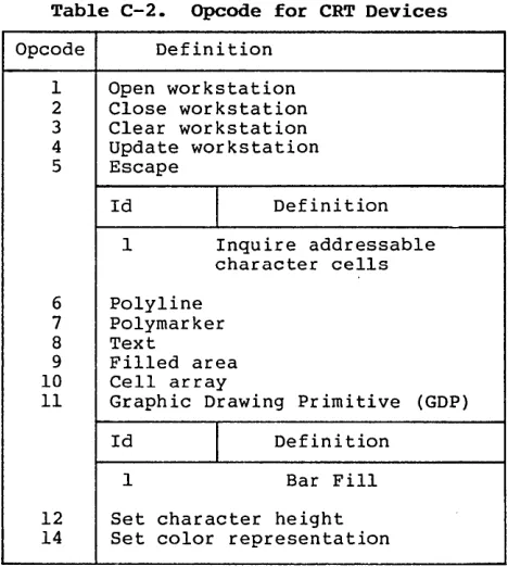
C-2. Opcode for CRT Devices • • • •
C-3. Opcode for Plotters and Printers •
Figures
1-1.
2-1.
GSX Provides Device-Independent Graphics •
GSX Memory Map • • • • • • • • • • • • •
C-46
C-47
C-48
C-5l
C-53
C-55
C-57
C-59
C-60
C-6l
3-3
C-49
C-60
C-6l
1-3
Section 1
INTRODUCTION
ABOUT THIS MANUAL
GSX BENEFITS
Section 1 identifies the features of GSX, the Graphics System Extension for your operating system. It explains what GSX does and how to use its graphics functions.
This section is for you if you are a new user of GSX. It assumes that your goal is to quickly hook up your application programs to your system's graphics capability.
If you are a system or an application programmer familiar with operating system concepts, this section introduces you to GSX.
Section 2 through Section 5 provides all the details you need to use GSX with your own unique graphics devices.
GSX adds graphics to your operating system, as follows:
• GSX supports DR Graph •• and DR Draw., two products that extend your graphics capabili ty. DR Graph allows you to graph and plot data by making simple menu selections. DR Draw lets you draw complex graphics images.
• GSX opens a world of application software. You can run any graphics application program that uses GSX with several 8080 and 8086 microcomputer operating systems.
• GSX promotes user por tabili ty. The inter face between you and GSX is identical to the inter face between you and your operating system.
GSX Programmer's Guide GSX Functions
GSX FUNCTIONS
Transforming Points
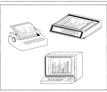
All graphics devices are not alike. Terminals, printers, and plotters draw lines, fill in areas, and produce text differently.
Wi th the Graphics System Extension for your operating system, you do not have to worry about device differences, because GSX handles all the differences and lets you talk to the devices through your application program as if the devices were all the same. GSX handles graphics requests and supplies the right program to run the device you are using.
All computer graphics are displayed on a coordinate system. GSX's job is to make sure the coordinate system that one device uses matches the coordinate system used by another. For example, with GSX your application program produces the same graphics image on your printer that i t does on your CRT. The linetypes and character sizes are the same.
GSX Programmer's Guide GSX Functions
fr~~~~~~~.//
:Jr-J
il
[image:14.470.73.425.60.362.2]GSX Programmer's Guide GSX Functions
Servicing Graphics Requests
Loading Device Drivers
Your application programs work with GSX through a standard calling sequence. GSX translates these standard calls to fi t the peculiarities of each graphics device (a printer or plotter, for example). The translation process makes your application programs device-independent. The programs can run on your system with the graphics device you are using.
For details about using GSX, refer to the GSX user's guide for your system.
Each graphics device is mechanically and electrically different, and requires a special program to run it. These programs· are called device drivers. GSX makes sure the right driver is loaded into memory so you can use the device you specify.
End of Section 1
Section 2
PROGRAMMER'S OVERVIEW
INTRODUCTION
GRAPHICS SYSTEM EXTENSION ARCHITECTURE
Th is section introduces the Graphics System Extension architecture with its components and their functions. Later sections describe each of these parts in detail.
GSX is the Graphics System Extension for
microcomputer operating systems. It
incorporates graphics capability into the operating system and provides a host and device-independent interface for your application programs. Graphics primitives are provided for implementing graphics applications with reduced programming effort. In addition, GSX enhances program portability by allowing an application to run on any operating system wi th
the GSX option. GSX also promotes programmer
portability by providing a common programming interface to graphics that is compatible with the most widely used operating systems.
GSX is an integral part of your operating system. Application programs interface to GSX
through a standard calling sequence. Drivers
for specific graphics devices translate the
standard GSX calls to the unique
characteristics of the device. In this way,
GSX provides device independence, and the peculiarities of the graphics device are not visible to the application program.
GSX consists of two parts that work together to give your system graphics capability:
GSX Programmer's Guide GSX Architecture
Graphics
Device Operating System (GOOS)
Graphics Input/Output System (GIOS)
The Graphics Device Operating System (GDOS) contains the basic host and device-independent graphics functions that can be called by your application program. GDOS provides a standard interface to graphics that is constant regardless of specific devices or host hardware, just as the disk operating systems standardize disk interfaces. Your application program accesses GDOS in much the same way that it accesses the disk operating
system. .
GDOS performs coordinate scaling so that your program can specify points in a normalized coordinate space. It uses device-specific information to translate the normalized coordinates into the corresponding values for your particular graphics device.
Multiple graphics devices can be supported under GSX within a single application. By referring to devices with a workstation identification number, an application program can send graphics information to anyone of several disk-resident devices. GDOS dynamically loads a specific device dr iver when requested by the application program, over laying the previous dr iver. This technique minimizes memory size requirements since only one driver is resident in memory at any time. For details see "LOADING GIOS FILES" in Section 3.
The Graphics Input/Output System (GIOS) is similar to any I/O system. It contains the device-specific code required to interface your particular graphics devices to the GDOS. GIOS consists of a set of device drivers that communicate directly with the graphics devices through the appropriate means. GSX requires a unique device driver for each different graphics device on your system. The term GIOS refers to the functional layer in GSX that holds the collection of available device drivers. The particular driver that is loaded into memory when required by your application is called a GIOS file. Al though a single program can use several graphics devices, GDOS loads only one GIOS file at a time.
GSX Programmer's Guide GSX Architecture
Enabling Graphics
GRAPHICS MODE INITIALIZATION
GIOS performs the graphics primitives of GSX consistent with the inherent capabilities of your graphics device. In some cases, a device driver emulates standard GOOS capabilities that are not provided by the graphics device hardware. For example, some devices require that dashed lines be simulated by a series of short vectors generated in the device driver.
The GSX package contains drivers for many of the most popular graphics devices for microcomputer systems. However, you can install your own custom device driver if necessary. We provide information in Section 4, "GIOS," to help you write your driver. The Virtual Oevice Interface (VOl) Specification in Appendix C defines all the required functions and parameter conventions.
A spec ial command allows you to enable and disable graphics functions from the command level of the operating system. This command enables GSX by loading GOOS and the default device dr iver and establishing the proper links to the operating system to allow an application program to access graphics devices. When GSX is disabled, it relinquishes all system memory space, leaving the maximum memory for nongraphics programs.
You must initialize GSX with a graphics command before running an application that uses GSX. Refer to your GSX user's guide for the GSX command that your system uses.
Upon entering the graphics mode, the operating system performs several actions. First, it brings GOOS-into memory along with the default driver, the first device driver listed in the Assignment Table.
GSX Programmer's Guide Graphics Mode Initialization
Finally, control returns to the operating system command interface module, which waits
for the next operator command. Note that a
warm start (usually invoked by CTRL-Z) does not disturb the graphics mode initialization. However, a cold start, or hardware reboot, disables GSX, which requires you to execute the GSX command after you reboot the system.
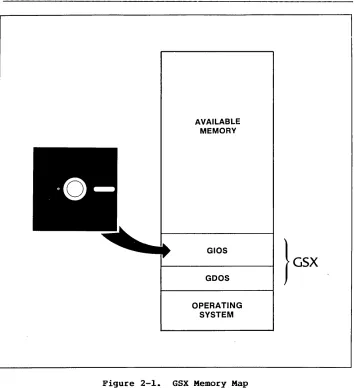
Figure 2-1 shows the location of the components of GSX after GSX graphics mode initialization.
When graphics mode is disabled, the memory used by GDOS and the GIOS file is made available to user programs, and control is returned to the operating system user interface module.
GSX Programmer's Guide Graphics Mode Initialization
AVAILABLE MEMORY
GIOS
GOOS
OPERATING SYSTEM
[image:20.468.76.430.60.448.2]GSX Programmer's Guide Application Programs
APPLICATION PROGRAMS
with appropriate calls to GDOS, you can write your application programs in assembly language or a high-level language that supports the GSX
call i ng conventions. You can compile or
assemble and link programs containing GSX calls in the normal manner.
End of Section 2
Section 3
GDOS
INTRODOCTION
GOOS FUNCTIONS
Graphics Calls
Dynamic Loading
This section describes the Graphics Oevice Operating System (GOOS) in detail, including GOOS functions, the GOOS calling sequence, and how device drivers are loaded.
GOOS per forms three functions dur ing the execution of a graphics application program:
• responds to GSX requests
• loads device drivers as required
• converts normalized coordinates to device coordinates
An application program accesses GOOS by making
calls to the operating system. Refer to
Appendixes A and B for GSX conventions for specific operating systems.
GSX Programmer's Guide GDOS Functions
Transforming Points
GDOS CALLING SEQUENCE
GDOS OPCODES
The application program passes all graphics coordinates to GDOS as Normalized Device Coordinates (NDC) in a range from
a
to 32,767 in both axes. Using information passed from the device driver when the workstation, or device, was opened, GDOS scales the, NDC units to the device coordinates. The full scale NDC space is always mapped to the full dimensions of your graphics device in each axis. This ensures that all your graphics information appears on the display surface regardless of the dimensions of the device.GSX gives you a standard way to access graphics capabili ties. This accessing method is called the Virtual Device Interface (VOl) because it makes all graphics devices appear "virtually" identical.
The implementation of the VDI employs the conventional disk operating system calling sequence. The application program calls GDOS by calling the operating system. For specific operating system calls, refer to Appendixes A and B. The program passes arguments to GDOS in a parameter l i s t , which consists of five arrays: a control array, an array of input parameters, an array of input point coordinates, an array of output parameters, and an array of output point coordinates. The specific graphics function to be performed by GDOS is indicated by an operation code in the parameter list.
Table 3-1 summarizes the GDOS opcodes. See Appendix C for a detailed description of all the operation codes including parameters.
GSX Programmer's Guide GDOS Opcodes
Table 3-1. GSX Operation Codes
Opcode Description
1 OPEN WORKSTATION initializes a graphics device (load driver if necessary).
2 CLOSE WORKSTATION stops graphics output to this workstation.
3 CLEAR WORKSTATION clears display device.
4 UPDATE WORKSTATION displays all pending graphics on workstation.
5 ESCAPE enables special device-dependent operation.
ID
I
Definition1 INQUIRE ADDRESSABLE CHARACTER CELLS returns number of addressable rows and columns.
2 ENTER GRAPHICS MODE enters graphics mode.
3 EXIT GRAPHICS MODE exits graphics mode.
4 CURSOR UP moves cursor up one row.
5 CURSOR DOWN moves cursor down one row.
6 CURSOR RIGHT moves cursor right one column.
7 CURSOR LEFT moves cursor left one column.
8 HOME CURSOR moves cursor to home position.
9 ERASE TO END OF SCREEN erases from current cursor position to end of screen.
10 ERASE TO END OF LINE erases from current cursor position to end of line.
[image:24.470.76.429.61.465.2]GSX Programmer's Guide GDOS Opcodes
Table 3-1. (continued)
Opcode Description
ID
I
Definition12 OUTPUT CURSOR ADDRESSABLE TEXT outputs text at the current alpha cursor position.
13 REVERSE VIDEO ON displays subsequent text in reverse video.
14 REVERSE VIDEO OFF displays subsequent text in standard video.
15 INQUIRE CURRENT CURSOR ADDRESS returns location of alpha cursor.
16 INQUIRE TABLET STATUS graphics tablet.
17 HARDCOPY makes hardcopy.
returns status of
18 PLACE GRAPHIC CURSOR AT LOCATION moves cursor directly to specified location.
19 REMOVE GRAPHIC CURSOR does not display cursor.
20-50 RESERVED (for future expansion).
51-100 UNUSED (and available).
6 POLYLINE outputs a polyline.
7 POLYMARKER outputs markers.
8 TEXT outputs text starting at specified position.
9 FILLED AREA displays and fills a polygon.
10 CELL ARRAY displays a cell array.
[image:25.470.40.395.59.479.2]GSX Programmer's Guide GDOS Opcodes
Table 3-1. (continued)
Opcode Description
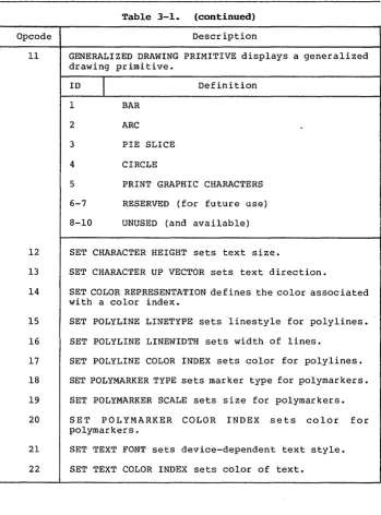
11 GENERALIZED DRAWING PRIMITIVE displays a generalized drawing primitive.
ID
I
Definition 1 BAR2 ARC
3 PIE SLICE
4 CIRCLE
5 PRINT GRAPHIC CHARACTERS
6-7 RESERVED (for future use)
8-10 UNUSED (and available)
12 SET CHARACTER HEIGHT sets text size.
13 SET CHARACTER UP VECTOR sets text direction.
14 SET COLOR REPRESENTATION defines the color associated with a color index.
15 SET POLYLINE LINETYPE sets linestyle for polylines.
16 SET POLYLINE LINEWIDTH sets width of lines.
17 SET POLYLINE COLOR INDEX sets color for polylines.
18 SET POLYMARKER TYPE sets marker type for polymarkers.
19 SET POLYMARKER SCALE sets size for polymarkers.
20 SET POLYMARKER COLOR INDEX sets color for polymarkers.
21 SET TEXT FONT sets device-dependent text style.
[image:26.470.74.424.60.533.2]GSX Programmer's Guide GDOS Opcodes
Table 3-1. (continued)
Opcode Description
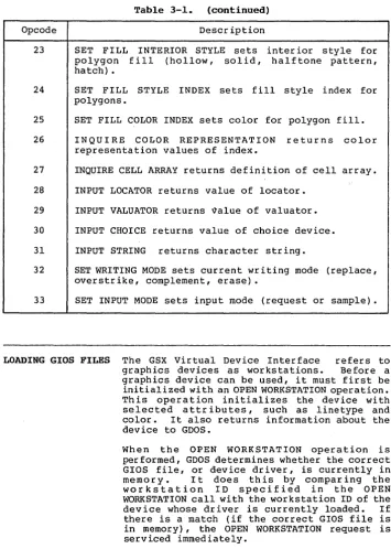
23 SET FILL INTERIOR STYLE sets polygon fill (hollow, solid, hatch) •
inter ior style for halftone pattern,
24 SET FILL STYLE INDEX sets fill style index for polygons.
25 SET FILL COLOR INDEX sets color for polygon fill.
26 INQUIRE COLOR REPRESENTATION returns color representation values of index.
27 INQUIRE CELL ARRAY returns definition of cell array.
28 INPUT LOCATOR returns value of locator.
29 INPUT VALUATOR returns ~alue of valuator.
30 INPUT CHOICE returns value of choice device.
31 INPUT STRING returns character string.
32 SET WRITING MODE sets current writing mode (replace, overstrike, complement, erase).
33 SET INPUT MODE sets input mode (request or sample).
LOADING GIOS FILES The GSX Virtual Device Interface refers to
graphics devices as workstations. Before a graphics device can be used, it must first be initialized wi th an OPEN WORKSTATION operation. Th is oper a t ion initializes the dev ice with selected attr ibutes, such as linetype and color. It also returns information about the device to GDOS.
When the OPEN WORKSTATION operation is performed, GDOS determines whether the correct GIOS file, or device driver, is currently in memory. It does this by comparing the workstation 10 specified in the OPEN WORKSTATION call with the workstation 10 of the device whose driver is currently loaded. If there is a match (if the correct GIOS file is in memory), the OPEN WORKSTATION request is serviced immediately.
[image:27.471.43.399.66.565.2]GSX Programmer's Guide Loading GIOS Files
Assignment Table Format
If a match does not occur, the GDOS must load the correct GIOS file. To find it, GOOS refers to a data structure called the Assignment Table, which contains information about the available device drivers and their location.
GOOS searches the Assignment Table for the first device driver entry with a driver number that matches the workstation 10 requested in the OPEN WORKSTATION call. If it finds the correct driver entry, GDOS loads the new GIOS file where the previous one was located. When the load is complete, GOOS finishes the OPEN WORKSTATION operation and returns to the calling program.
If there is no match in the Assignment Table when a new driver is required, GOOS returns wi thou t loading a dr i ver, and the prev ious graphics device continues to operate as the open workstation.
GSX Programmer's Guide Loading GIOS Files
The format for entries in the Assignment Table is as follows:
DDXd:filenameicomments
DD = logical driver number X
=
spaced
=
disk drive codefilename = driver filename (valid unambiguous
filename of up to eight characters
and filetype, .SYS extension
assumed as default)
comments any text string
For example, valid entries in the Table would be as follows:
21 A:PRINTR i printer
11 A:DDPLOT i plotter
1 B:CRTDRV i system console
2 E:DRlVER.ABC 14 DRlVER2.SYS
Note: The driver filename can have any
filetypei however, .SYS is assumed if the
filetype field is blank. The drive specified
in the GSX graphics mode command is used as the default for driver filenames that do not have an explicit drive reference. Extra spaces can be inserted.
The following convention for assigning device driver numbers, or workstation IDs, to graphics devices ensures the maximum degree of device independence within application programs. The convention for driver numbers is as follows:
Device Number
1-10 11-20 21-30
31-40
41-50
Device Type
CRT Plotter Printer Metafile Other devices
Assign the lowest device number wi thin a device type when you use only one device.
GSX Programmer's Guide Loading GIOS Files
Memory Management When graphics mode is enabled, GSX allocates
memory for the first device driver in the Assignment Table. This driver is referred to as the default dev ice dr iver. Subsequently, GDOS causes all new drivers to be loaded into the same area where memory was allotted for the origJnal device driver. Ensure that the first driver in the Assignment Table is the largest driver to be loaded so that ample memory space is allocated by the GSX loader for all subsequent drivers. GSX returns an error to the caller and the new driver is not loaded if an attempt is made to load a driver larger than the default driver.
Section 4
GIOS
INTRODUCTION
PURPOSE OF GIOS
This section describes the Graphics Input/ Output System, or GIOS. With this information you can wr i te and install your own custom drivers for unique graphic devices.
As we discussed earlier, GSX is composed of two components: the Graphics Device Operating System (GOOS) and the Graphics Input/Output System (GIOS). GOOS contains the device-independen t graphics functions, while GIOS con ta ins the dev ice-dependent code. This division is consistent with the philosophy of isolating device dependencies so that the principal parts of the operating system are tr anspor table to many systems. This also allows applications to run independent of the specific devices connected to the system. In this context, GIOS is analogous to the I/O systems but pertains to graphics devices only. GIOS contains a GIOS file, or device driver, for each of the graphics devices on the system. Each GIOS file contains code to communicate with a single specific graphics device.
A difference between GIOS and I/O systems is tha t whereas all dev ice dr ivers contained wi th in I/O systems are resident in memory simul taneously, only one graphics device dr iver is resident at any time. That is, only one graphics device is active at a time, although the active device can be changed by a request from the application program. GOOS ensures that the correct driver is in memory when
GSX Programmer's Guide GIOS Functions
GIOS FUNCTIONS
VIRTUAL DEVICE INTERFACE SPECIFICATION
Each of the GIOS files uses the intr insic graphics capabilities of devices to implement graphics primitives for GDOS. In some cases, the graphics device does not support all the GDOS operations directly, and the driver must emulate the capability in software. For example, if a plotter cannot produce a dashed line, the driver must emulate it by converting a single dashed line into a series of short vectors and transmitting them to the plotter, giving the same end result.
Device drivers must conform to the GSX Virtual Device Interface (VOl) Specification. The VOl specifies the calling sequence to access device driver functions as well as the syntax and semantics of the data structures that communicate across the interface.
The application program passes arguments to device drivers in a parameter list pointed to by the contents of specific registers. The parameter list is in the form of five arrays, as follows:
• control array
• array of input parameters
• array of input point coordinates • array of output parameters
• array of output point coordinates
The application program specifies the graphics function to be performed by a device driver with an operation code in the control array.
All array elements are type INTEGER (2 bytes). All arrays are I-based; that is, the double-word address at Parameter Block (PB) points to the f i r s t element of the control array (contrl (1)) • The meaning of the input and output parameter arrays is dependent on the opcode. See Appendix C, "Virtual Device Interface Specification," for details.
GSX Programmer's Guide Virtual Device Specification
The application program passes all graphics coordinates to the device driver as device coordinates. Using information passed from the device driver when the workstation, or device, was opened, GDOS scales the NDC coordinates, passed from the application to the coordinates of the specific device.
The full-scale NDC space is always mapped to the full dimensions of your graphics device in each axis. This ensures that all your graphics information is visible on the display surface regardless of the actual device dimensions.
However, NDC space is larger than device space. For example, the NDC space for a device is 32K by 32K NDC units. The target device measures 640 by 200 pixels. The size of an NDC pixel is 51 by 164 NDC units. When GSX returns the value of the pixel to an application, the value of the bottom left corner of the NDC pixel is returned by GSX. Therefore, to avoid cumulative errors caused by round-off procedures in your application, you should add an offset of one-half an NDC pixel to the value returned by GSX when you are transforming coordinates up and down GSX.
If your device has an aspect ratio that is not 1: 1 (tha t is, the display surface is not square) and you wish to prevent distortion between your world coordinate system and the device coordinate system, your application must use different scaling factors in the X and Y axes to compensate for the asymmetry of your dev ice. For example, if you are using a typical CRT device with an aspect ratio of 3:4
(vertical:horizontal) to produce a perfect square on the display, you would draw a figure with 4000 NDC units vertically and 3000 NDC units horizontally. That is, the scaling factor for the vertical dimension is 4/3 of the hor izontal direction. For most noncritical applications you need not make this adjustment.
GSX Programmer's Guide Creating a GIOS File
CREATING A GIOS FILE
Device driver files that are part of GIOS must be in standard executable command format so they can be loaded by GDOS. These files may be renamed to .SYS, the default filetype for GSX GIOS files. You can write a device driver in any language as long as the functions and parameter passing conventions conform to the Virtual Device" Interface Specification given above. After assembling or compiling your dr iver source, link i t wi th any required external subroutines and run-time support libraries to produce a load module.
The name of a GIOS file can consist of eight characters or less with a .SYS filetype. In addition, the driver must be included in the Assignment Table, which is a text file named ASSIGN.SYS on the current default drive.
Refer to "Assignment Table Format" in Section 3 for more details about the ASSIGN.SYS and the correct format for each entry.
End of Section 4
Section 5
OPERATING PROCEDURES
INTRODUCTION
GSX
DISTRIBUTION FILES
RUNNING GRAPHICS APPLICATIONS UNDER GSX
This section explains how to use GSX in your graphics applications.
When you receive your GSX distribution disk, first check that all required files have been included.
Refer to your GSX user's guide for procedures that check and duplicate the distribution disk.
If any files are missing, contact your distributor to receive a new disk. If all files are present, duplicate the distribution disk using the PIP utility and store your distribution disk in a safe place. Then, using the duplicate disk, transfer the GSX files to a working system disk. Always use the duplicate disk to generate any new copies of GSX. Do not use the distribution disk for routine operations.
To use the graphics features provided by GSX, you must ensure that several conditions are met:
1. In your application program you must conform to the GSX calling convention to access graphics primitives. This involves making a call to the operating system, which points to a parameter list. This list provides information to GSX and also returns information to the calling program. The details of this procedure are contained in Section 3, "GDOS," 'Section 4, "GIOS," and the appendixes.
GSX Programmer's Guide Running Graphics Applications
DETERMINING MEMORY REQUIREMENTS
3. The required device drivers must be present on the disk specified in the GSX graphics mode command, or in the current default drive if no drive is specified, when your program is executed. Also, the Assignment Table (ASSIGN.SYS) must contain the names of your device drivers and a logical device number or workstation ID that corresponds to the correct device driver. The details of device driver and Assignment Table requ i r emen ts are included in Section 3, "GDOS," and Section 4, "GIOS."
4. -After successfully compiling or assembling and linking your application program you can run it just like any other program, but first you must ensure that GSX is active. You can enable GSX graphics with the GSX graphics mode command documented in the GSX user's guide for your system.
To determine the amount of stack space required to run a given application, make the following calculation:
GSX stack requirements:
Open workstation call approximately 500 bytes
All others = ptsin size + 128
ptsin is the point array passed to the device driver from the application program (two words for each point).
The stack requirement is the largest of the two re s ul ting values. This stack space must be ava ilable in the application program stack area.
The memory required by GDOS is less than 3 kilobytes. This is allocated when the GSX graphics mode command is executed. Space for the default device driver is also allocated at this time. The default device dr iver should be the largest device driver so that sufficient space is allocated for other dr ivers loaded during execution of your application.
GSX Programmer's Guide Debugging Graphics Application under GSX
DEBUGGING GRAPHICS APPLICATIONS UNDER GSX
WRITING A NEW DEVICE DRIVER
Graphics programs can be debugged with a debugger, as can any GSX application. The default device driver and GDOS are loaded after the command has been executed. Your graphics application program is loaded in the normal manner for applications on your operating system.
GSX is distributed with a number of device drivers for popular graphics devices. If your devices are included (refer to your GSX user's guide for a summary of the supported devices) , you only need to edit the Assignment Table file with a text editor to ensure that it reflects the logical device number assignments that you desire. However, if your device is not supported, you must create a driver program that conforms to the VOl specification. You can write a driver in any language, but at least part of it is usually implemented in assembler due to the low-level hardware interface required.
Your driver must provide the functions listed as required in the VOl specification and must observe the VDI parameter passing conventions. In some cases the capability specified by VOl is not available in the graphics device and the func tion must be emulated by the dr iver software. For example, dashed lines can be generated by the dr iver if they are not directly available in the device. The complete VDI specification is in Appendix C, and the parameter passing conventions are discuss~d in Section 3, "GDOS," and Section 4, "GIOS."
Appendix A
GSX
CALLING CONVENTIONS FOR
CP/M
INTRODUCTION
GS& SKELETON DEVICE DRIVER
FORMAT
Input Parameters
Output Parameters
This appendix br iefly outlines the components of a skeleton device driver for GSX on CP/M for 8080 microprocessors. It also summarizes the GSX GDOS calling conventions for CP/M.
The GSX skeleton dev ice dr i ver . descr ibes the components required for a CP/M system.
Function: contrl(l) contrl(2) contrl(4) contrl(6-n) intin ptsin contrl(3) contrl(S) contrl(6-n) intout ptsout
GSX skeleton device driver
Opcode for driver function Number of vertices in array pts in. Each vertex cons ists of an x and a y coordinate so the length of this array is twice as long as the number of vertices specified.
Length of integer array intin Opcode dependent information
Array of parameters Array of data
integer input
input coordinate
Number of vertices in array ptsout. Each vertex consists of an x and a y coordinate so the length of this array is twice as long as the number of vertices specified.
Length of integer array intout
Opcode dependent information
Array of integer output parameters
GSX Programmer's Guide Format
All data passed to the device driver is assumed to be 2-byte INTEGERS.
All coordinates passed to GSX are in Normalized Device Coordinates (0-32767 along each axis). These units are mapped to the actual device units (for example, rasters for CRTs or steps for plotters and printers) by GSX so that all coordinates passed to the device driver are in device units.
Because both input and output coordinates are converted by GSX, both the calling routine and the device driver must ensure that the input vertex count (contrl (2)) and output vertex count (contrl(3)) are set. The calling routine must set contrl(2) to 0 if no x,y coordinates are being passed to GSX. Similarly, the device dr i ver must set contrl (3) to 0 if no x ,y coordinates are being returned through GSX.
Because 0-32767 maps to the full extent on each axis, coordinate values are scaled differently on the x and y axes of devices that do not have a square display.
The BOOS call to access GSX and the GIOS in CP/M is as follows:
BOOS opcode (in C register) for GSX call
=
115Parameter Block (address is passed in DE) :
PB Address of contrl
PB+ls Address of intin
PB+2s Address of ptsin
PB+3s Address of intout
PB+4s Address of ptsout
s is the number of bytes used for each argument
in the parameter block. For CP/M, this is 2
bytes.
All opcodes must be recognized, whether they produce any action or not. A list of required opcodes for CRT devices, plotters, and pr inters follows the specification. These opcodes must
be present and perform as specified. All
opcodes should be implemented whenever possible because this gives better quality graphics.
GSX Programmer's Guide Format
GooS CALLING CONVENTIONS
For CP/M, device driver I/O is done through BDOS (Basic Disk Operating System) calls. CRT devices are assumed to be the console device. Plotters are assumed to be connected as the reader or punch device. Printers are assumed to be connected as the list device.
The GDOS calling below.
sequence is summarized
Function code (in register C)
=
115 Parameter block address in register DEParameter Block Contents:
PB PB+2 PB+4
PB+6 PB+8
Address of control array
Address of input parameter array Address of input point coordinate array
Address of output parameter array Address of output point coordinate array
Control Array on Input:
contrl(l) contrl(2)
contrl(4) contrl(6-n)
Opcode for driver function Number of vertices in input point array
Length of input parameter array Opcode dependent
Input Parameter Array:
intin Array of input parameters
Input Coordinate Array:
Appendix B
GSX CALLING CONVENTIONS
FOR CP/M, IBM PC DOS, AND MS-DOS
INTRODUCTION
GDOS CALLING SEQUENCE
This appendix outlines the GSX calling sequence for the GDOS, the procedure for invoking device drivers, and error messages when you use GSX on CP/M-86, IBM PC DOS, and MS-DOS.
The GDOS calling sequence is outlined below.
Access via interrupt 224
Function code (in register Cx)
=
0473h (hex)Parameter block address in registers Os-segment and Ox-offset
Parameter Block Contents:
PB PB+4
PB+8
PB+12
PB+16
Double-word address of control array Double-word address of input parameter array
Double-word address of input point coordinate array
Double-word address of output parameter array
Double-word address of output point coordinate array
Control Array on Input:
contrl(l} contrl(2}
contrl(4}
contrl (6-n)
Opcode for driver function Number of vertices (not coordinates) in input coordinate point array
(ptsin)
Length of input parameter array
GSX Programmer's Guide GDOS Calling Sequence
Input Parameter Array:
intin Array of input parameters (length of array is opcode dependen t and specif ied in contrl (4))
Input Point Coordinate Array:
ptsin Array of input coordinates (each point is specified by an X and Y coordinate pair given in Normalized Device Coordinates between 0 and 32,767, with length contrl(2)*2)
Control Array on Output:
contrl(3)
contrl(5)
contrl{6-n)
Number of vertices (not coordinates) in output point array (ptsout)
Number of elements in output parameter array (intout) Opcode dependent
Output Parameter Array:
intout Array of output parameters (length of array is opcode dependent)
Output Point Coordinate Array:
ptsout
B-2
GSX Programmer's Guide GDOS Calling Sequence
All array elements are type INTEGER (2 bytes) • All arrays are I-based; that is, the double-word address at PB points to the first element of the control array (contrl(l)). The meaning of the input and output parameter arrays is dependen t on the opcode. See Appendix C, "Virtual Device Interface Specification," for details.
GDOS preserves the BP (base pointer) and DS (data segment) registers. All other registers are subject to change when returned from GDOS.
INVOKING DEVICE DRIVERS
Device drivers are invoked with a CalIf from GSX and should return with a Retf. The driver must switch to its own stack for internal use, except for an allowed overhead for a few pushes to save the caller's context. The following entry procedure is recommended to provide an error free calling sequence:
CGroup Group Driver _Code
Driver _Code CSeg
Public Driver
Driver: Mov Ax,Sp Save caller's stack pointers Mov Bx,Ss
Note that Mov Ss,xxx Mov Sp,xxx is not interruptible on 8086/8088.
Mov Ss,StackBase Switch to driver's stack Mov Sp,Offset Top_Stack
Push Bx Push caller's stack pointer Push Ax
Push Bp Save caller's frame Push Ds Save parameter pointer Push Dx
GSX Programmer's Guide Invoking Device Drivers
Invoke the driver. Ds:Dx points to the parameter block. It returns with a Retf.
CalIf Dd_Driver
Popf Pop Dx Pop Ds Pop Bp Pop Ax Pop Bx Mov Ss,Bx Mov Sp,Ax Retf
StackBase Dw Seg Top_Stack
Dd Driver_Code CSeg
Extrn Dd Driver
Stack SSeg Rs 16
Invoke the driver with Ds:Dx
Restore caller's direction flag Restore caller's Ds:Dx
Restore caller's stack frame Restore caller's Ss:Sp
via Bx and Ax
:Far
This module pushes 8 words
~ Top_Stack is defined in the' last module linked in. Extrn
End
:Byte
After coding, assembling and linking your device driver, you have a .CMD file if you use CP/M. First change the filetype to .SYS using the CP/M RENAME command or a similar command for your operating system:
A>REN GIOSXX.SYS=GIOSXX.CMD
Then, to make this driver known to GSX, include its name in the Assignment Table. This table is located in file ASSIGN.SYS and is simply a text file with a specific format containing the names of driver files and the logical device numbers or workstation IDs that you wish to associate with particular devices. Refer to Section 3, "GDOS," or Section 4, "GIOS," for details.
GSX Programmer's Guide Error Messages
ERROR MESSAGES In general, registers and flags (including the direction flag) are not restored upon returning from a call to GSX. The GIOS file will preserve the DS, SS and CS registers and BP and SP, but it is not required to preserve any others. GSX does not change any registers as returned from the GIOS except during an OPEN WORKSTATION command. In this case Ax is modified to return status information (the flags are also modified by this command).
The meaning of the contents of Ax on returning from the OPEN WORKSTATION call is as follows:
AL=O AL=255
AH
o
I 2 3 4
5
6
7
workstation opened successfully error condition--device driver not loaded. In th is case AH has a further meaning:
ASSIGN.SYS not found Syntax error in ASSIGN.SYS
Device ID not found in ASSIGN.SYS Close error on ASSIGN.SYS
Device driver file specified in ASSIGN.SYS not found
Device driver file specified in ASSIGN.SYS empty
Syntax error on file specified in ASSIGN.SYS (that is, absolute code segment or not .CMD format)
Not enough room for file specified
If a read error occurs during the transfer of a GIOS file when an OPEN WORKSTATION call is in progress, the application .program is terminated, a message is displayed, and control is returned to the operating system user inter face module. The following error messages can be displayed in response to GSX calls:
GSX CS:IP GIOS load error on Id xxxxh (hex)
GSX Programmer's Guide Error Messages
GSX CS:IP GIOS invalid
The currently loaded device driver is invalid. This error probably occurred after a load error when the application does not perform an OPEN WORK.STATION command as the first graphics operation.
GSX CS:IP Illegal function: (Cx)
An invalid function code (~0473h) was specified in Cx. The erroneous code is displayed.
Refer to the GSX user's guide for your system for additional error messages output by GSX.
End of Appendix B
Appendix C
VIRTUAL DEVICE INTERFACE (VOl) SPECIFICATION
INTRODUCTION
FORMAT
Input Parameters
Output Parameters
This appendix contains the specification of the Virtual Device Interface (VDI). The VDI defines how device drivers interface to GDOS, the device-independent portion of GSX. The context for this document is from the DEVICE DRIVER point of view. All coordinate information is assumed to be in device coordinate space.
Function:
contrl(l} contrl (2)
contrl(4} contrl(6-n}
intin
ptsin
contrl(3}
contrl(5}
contrl(6-n}
GSX graphics operation
Opcode for driver function. Number of vertices in array ptsin. Each vertex consists of an x and a y coordinate pair so the length of this array is twice as long as the number of vertices specified. Length of integer array intin. Opcode dependent information.
Array of integer input parameters.
Array of input point coordinate data.
Number of vertices in array ptsout. Each vertex consists of an x and a y coordinate pair so the length of this array is twice as long as the number of vertices specified. Other data may be passed back here depending on the opcode. Length of integer array intout.
GSX Programmer's Guide Format
Notes
intout
ptsout
Array of integer output point parameters.
Array of output point coordinate data.
All data passed to the device driver is assumed to be 2-byte INTEGERS, including individual characters in character strings.
All coordinates passed to GSX are in Normalized Device Coordinates (0-32767 along each axis). These units are then mapped to the actual device units (for example, rasters for CRTs or steps for plotters and printers) by GSX so that all coordinates passed to the device dr iver are in device units.
Because both input and output coordinates are converted by GSX, both the calling routine and the device driver must make sure that the input vertex count (contrl(2)) and output vertex count (contrl(3)) are set. The calling routine must set contrl(2) to 0 if no x,y coordinates
are are being passed to GSX. Similarly, the
device driver must set contrl(3) to 0 if no x,y coordinates are being returned through GSX. Coordinates returned by GSX are assumed to be
the bot tom le ft edge of the pixel. As a
consequence, points at the top and right edges of the device coordinate system will not be at the edge of the Normalized Device Coordinates
(NDC) system. Exactly how far away they will
be is device dependent.
Because 0-32767 maps to the full extent on each axis, coordinate values are scaled differently on the x and y axes of devices that do not have a square display.
All references to arrays are l-based; that is, subscripted element I is the first element in the array.
On calls to the GDOS the number of arguments passed in the intin array (contrl(4)), and the maximum size of the intout array (contrl(S)) should be set by the application. On return to the GDOS by the GIOS the number of arguments in the intout array should be set by the GIOS. Refer to Appendixes A and B for GDOS calling conventions for specific operating systems.
GSX Programmer's Guide Format
All opcodes must be recognized, whether or not they produce any action. If an opcode is out of range then no action is performed. A list of required opcodes for CRT devices, plotters, and printers follows the specification. These opcodes must be present and perform as specified. All opcodes should be implemented whenever possible since full implementation gives better quality graphics.
GSX Programmer's Guide Open Workstation
OPEN WORKSTATION Initialize a graphic workstation.
Input Output contrl(l} contrl(2} contrl(4} intin intin(l} intin(2) intin(3) intin(4) intin(5} intin(6) intin(7} intin(8} intin(9} intin(lO} contrl(3} contrl (5) in tou t (l)
intout(2}
intout(3}
intout(4}
intout(5}
C-4
Opcode = 1
o
Length of intin = 10
Initial defaults (for example, linestyle color and character size)
Workstation identifier (device driver id). This value is used to determine which device driver to dynamically load into memory.
Linetype
Polyline color index Marker type
Polymarker color index Text font
Text color index Fill interior style Fill style index Fill color index
Number of output vertices = 6 Length of intout = 45
Maximum addressable width of screen/plotter in rasters/ steps assuming a 0 start point (for example, a resolution of 640 implies an addressable area of 0-639, so intout(I)=639} Maximum addressable height of screen/plotter in rasters/ steps assuming a 0 start point (for example, a resolution of 480 implies an addressable area of 0-479, so intout(2)=479} Device Coordinate units flag
0= Device capable of producing precisely scaled image (typically plotters and printers)
1 Dev ice not capable of precisely scaled image
(CRTs)
Width of one pixel step, or aspect ratio in micrometers
Height of one pixel step, or aspect ratio in micrometers
(plotter for CRT)
GSX Programmer's Guide intout(6} intout(7} intout(8} intout(9} intout(lO} intout(ll} intout(12} intout(13} intout(14}
intout(lS}
-- intout(16}-intout(2S}
-- intout(26}-intout(3S}
--Open Workstation
Number of character heights
o
=
continuous scaling Number of linetypes Number of line widths Number of marker types Number of marker sizes Number of fontsNumber of patterns Number of hatch styles
Number of predefined colors (must be at least 2 even for monochrome device). This is the number of colors that can be displayed on the dev ice simultaneously.
Number of Generalized Drawing Primitives (GDPs)
Linear 1 ist of GDP number s supported -1 no more GDPs in l i s t . Application should search list until finding a -1 for the desired GDP.
1 bar 2 arc 3 pie slice 4 circle 5 ruling chars
Linear list of attribute set associated with each GDP
-1 no more GDPs
o
polyline 1 polymarker 2 text 3 fill area 4 noneintout(36} -- Color capability flag
o
no 1 yesintout(37} -- Text rotation capability flag
GSX Programmer's Guide Open Workstation
intout(38) -- Fill area capability flag
o
no 1 -- yesintout(39) -- Read cell array operation capability flag
o
no 1 -- yesintout(40) -- Number of available colors (total number of colors in color palette)
intout(4l) intout(42) intout(43) intout(44) intout(45) ptsout (1) ptsout(2) ptsout(3) ptsout(4) ptsout(S) ptsout(6) ptsout(7) ptsout(8) ptsout(9) ptsout(lO)
o
continuous device(more than 32767 colors) 2 monochrome (black and
white)
>2 n u m b e r 0 f c o l o r s
available
Number of locator devices available
Numbe r 0 f valua tor dev ices
available
Number of choice devices available
Number of string devices available
Workstation type
o
Output only 1 Input only 2 Input/Output3 Device independent segment storage
4 GKS Metafile output
o
Minimum character height in device units (not cell size)
o
Maximum character height in device units (not cell size) Minimum line width in device units
o
C-6
Maximum line width in device units
o
o
GSX Programmer's Guide
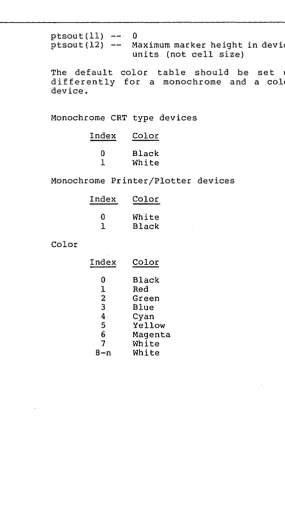
ptsout (11) ptsout (12)
Open Workstation
a
Maximum marker height in device units (not cell size)
The default color differently for device.
table should be set up a monochrome and a color
Monochrome CRT type devices
Index Color
a
Black 1 WhiteMonochrome Printer/Plotter devices
Index Color
a
White 1 BlackColor
Index Color
[image:56.470.133.418.37.552.2]GSX Programmer's Guide Open Workstation
Description
Other default values that should be set by the driver during initialization are as follows:
Character height
Character up vector
Line width
Marker height Writing mode Input mode
Minimum character height
90 degrees
counterclockwise from the right horizontal (0 degrees rotation) 1 device unit (raster, plotter step)
Minimum marker height Replace
Request for all input classes (locator, valuator, choice, string)
The Open Workstation operation causes a graphics device to become the current device for the application program. The device is initialized with the parameters in the input array and information about the device is returned to
Goos. The graphic device is selected, and, if
it is a CRT, the screen is cleared and the alpha device is deselected and blanked.
GSX Programmer's Guide Close Workstation
CLOSE WORKSTATION
Input
Output
Description
CLEAR WORKSTATION
Input
Output
Description
Stop all graphics output to this workstation.
contrl (1) contrl(2)
contrl(3)
--Opcode
o
o
2
The Close Workstation operation terminates the graphics device properly and prevents any further output to the device. If the device is a CRT, the alpha device is selected, the screen is cleared, and the graphics de·vice is deselected and blanked. If the device is a printer, then an update is executed.
Clear CRT screen or prompt for new paper on plotter.
contrl(l) contrl(2)
contrl(3)
--Opcode
o
o
3
GSX Programmer's Guide update Workstation
UPDATE WORKSTATION Display all pending graphics on workstation.
Input Output Description ESCAPE Input contrl(l) contrl(2) Opcode
o
4contrl (3) -- ·0
The Update Workstation operation causes all pending graphics commands that are queued to be executed immediately. The operation is analogous to flushing buffers. For pr inter drivers this call must be used to start output to the printer.
Perform device specific operation.
contrl(l) contr 1 (2) contrl (4) contrl(6) 1 2 3 4 5 6 7 8 9 10 11 12 13 14 15 16 17 18 19 20-50 51-100
Opcode = 5
Number of input vertices Number of input parameters Function identifier
INQUIRE ADDRESSABLE CHARACTER CELLS
ENTER GRAPHICS MODE EXIT GRAPHICS MODE CURSOR UP
CURSOR DOWN CURSOR RIGHT CURSOR LEFT HOME CURSOR
ERASE TO END OF SCREEN ERASE TO END OF LINE DIRECT CURSOR ADDRESS
OUTPUT CURSOR ADDRESSABLE TEXT REVERSE VIDEO ON
REVERSE VIDEO OFF
INQUIRE CURRENT CURSOR ADDRESS INQUIRE TABLET STATUS
HARDCOPY
PLACE GRAPHIC CURSOR AT LOCATION
REMOVE LAST GRAPHIC CURSOR UNUSED BUT RESERVED FOR FUTURE EXPANSION
UNUSED AND AVAILABLE FOR USE
GSX Programmer's Guide Escape
Output
Description
intin
ptsin
contrl(3) contrl(S)
intout ptsout
Function dependent information (described on following pages) Array of input coordinates for escape function
Number of output vertices Number of output parameters
Array of output parameters Array of output coordinates
GSX Programmer's Guide Escape
ESCAPE: INQUIRE ADDRESSABLE CHARACTER CELLS
Input
Output
Description
Return the number of alpha cursor addressable columns and alpha cursor addressable rows.
contrl(2) contrl (6)
contrl(3) intout(l)
intout(2)
--o
Function ID 1
o
Number of addressable rows on the screen, typically 24 (-1 indicates cursor addressing not possible)
Number of addressable columns on the screen, typically 80 (-1 ind ica tes cursor addressing not possible)
This operation returns information to the calling program about the number of vertical (rows) and hor izontal (columns) positions where the alpha cursor can be positioned on the screen.