ADAPTIVE DYNAMIC RESOURCE SYNCHRONIZATION
DISTRIBUTED MUTUAL EXCLUSION ALGORITHM
(ADRS)
P
1
P
MARIAM ITRIQ,P
2
P
WAFA DBABAT,P
3
P
AHMAD SHARIEH
P
1
P
Instructor, BIT Dept., King Abdullah II School for Information Technology, The University of Jordan
P
2
P
Instructor, SE Dept., Prince Abdullah Bin Ghazi Faculty of Information Technology, Balqa’ Applied University
P
3
P
Prof., CS Dept., King Abdullah II School for Information Technology, The University of Jordan E-mail: 0TP
1
PU
[email protected]U0T , 0TP
2
PU
[email protected]U0T , 0TP
3
PU
ABSTRACT
Existing mutual exclusion algorithms for distributed systems are not well suitable for mobile system, because of several limitations: small memory, a relatively slow processor, low power batteries, and communicate over low bandwidth wireless communication links. In this paper, we adapted the DRS mutual exclusion algorithm applying it on the infrastructure machines that communicate directly with the mobile hosts, called Mobile Support Stations (MSS) with some modifications. As DRS algorithm, the adapted version ADRS tends to minimize the number of messages needed to be transmitted in the system, by reducing the number of sites involved in the mutual exclusion decision, and reducing the amount of storage needed at different sites of the system.
Keywords: Distributed systems, Permission, Synchronization, Mutual exclusion, MSS.
1. INTRODUCTION
The resource allocation problem is one of the most important problems in mobile systems due to the special characteristic of mobile environment: the sites do not share any memory and communicate completely by message passing. The wireless communication channels were used by the mobile system have lower bandwidth than the wired communication links. Any distributed mutual exclusion algorithm should take this constraint into consideration [1][2].
Many distributed algorithms for mutual exclusion that have been proposed since last decade classified in two categories: token based and permission based [3], permission based mutual algorithms [4][5][6][7] impose that a requesting node must receive permission from other nodes through cycles of messages exchanged among nodes. Examples of permission based mutual exclusion algorithms are Lamport’s algorithm which require 3(n-1) messages [8], Ricart and Agrawala [13] for requires 2(n - 1) messages per CS entry, Mamoru Maekawa proposed a distributed mutual exclusion algorithm
[5] which requires only 3√n to 5√n messages per
mutual exclusion. In token based mutual exclusion algorithms [1][9][2] a unique token is shared among set of nodes, if the token is available locally no communication is needed and the node that hold the token can enter critical section (CS), otherwise an adequate mechanism must be taken to locate it[10]. In addition, an expensive regenerate protocol needed if the node that holds the token fails during holding it. Suzuki and Kasami's token-based algorithm requires n messages per CS entry [11]; Raymond's algorithm [2] complexity is O(log n) under light demand. Algorithm proposed by Pranay, Chaudhuri, Mehmet Hakan Karaata [12] achieves the message complexity as O(n1/3) per mutual exclusion
based on the idea of queues, which require a relatively large amount of storage that is not available in the mobile systems.
In the last ten years a new approach has been taken to allocate resource in mobile ad-hoc network (MANET), different Cluster based algorithms are proposed [13][14][15] to reducing the message complexity, in this algorithms no need for specific coordinator (message router) for a cluster. Thus, no reelection of coordinator is required. The Dynamic resource synchronizer (DRS) algorithm [16], it’s called dynamic because the node that manage the critical section “synchronizer” is dynamically changed according to certain criteria that reduce massage traffic among the nodes[16 ].
In this paper we proposed an idea to achieve the synchronization, also its try to overcome the limitations for the literature distributed mutual exclusion algorithms. This idea is an updated version from a DRS algorithm mentioned in [16].
The organization of this paper is as follows: Section 2 presents briefly describes the DRS algorithm. The Mobile System Environment and Model described in section 3. In section 4 we describe our adaptive DRS algorithm and its assumptions. Section 5 traces the execution rules of the algorithm. The correctness of ADRS is presented in section 6. In section 8 we discuss the performance issues of ADRS. And finally we conclude our work in section 8.
2. OVERVIEW OF DRS
DRS algorithm assumed that the system consists of n independent mobile nodes labeled (N0, N1, …, Nn), communicating by message passing over a wireless network. Each node in the system is assumed to be running an application whose states are partitioned into four sections:
WAITING: where the node has requested access to the CS.
CRITICAL: in which the node is executing the CS.
SYNCHRONIZER: node currently responsible for handling mutual exclusion access to the CS. There is one and only one node in this state in the system at any instance. Initially one node is set to this state.
REMINDER: where the node is neither requesting nor executing the CS. All nodes are initialized to this state.
Nodes in the system cycle through REMINDER to WAITING to CRITICAL to REMINDER to SYNCHRONIZER state, and nodes never stop
executing while CRITICAL. A node exits the SYNCHRONIZER state either if any other node exits CS.
The major data structures used by DRS algorithm were:
-Status: indicates whether a node is in the
WAITING, CRITICAL,
SYNCHRONIZER , or REMINDER section.
-Next: pointer to the process next in the logical
ring. Processes are connected to each other forming a logical ring.
-Queue: pointer to the process next in the waiting queue. This pointer is set to nil if the process is the one at the end of the queue or if it is not involved in the queue.
-Busy: a Boolean flag used only by the
SYNCHRONIZER, it is set to TRUE if any node in the system is currently CRITICAL. Initially this is FALSE in all nodes.
-Synch: address of the current SYNCHRONIZER node.
-Critical: address of the node currently in the CRITICAL state. The node uses this variable when it is in the SYNCHRONIZER state.
Five types of messages are communicated in the system:
-REQUEST: a message sends by a REMINDER
node that is wishing to be
CRITICAL.
-GRANT: a message sends by the SYNCHRONIZER to the next process in queue.
-RELEASE: a message sends by the CRITICAL to the SYNCHRONIZER when exiting the CS.
-YAS (You Are Synchronizer): send by the
SYNCHRONIZER to transfer the synchronization state.
-ADD: a message send by the SYNCHRONIZER
to add a new node to the queue.
-GHANGE: a message sends by the SYNCHRONIZER to the CRITICAL to inform it of the SYNCHRONIZER state transfer.
long time, to insure fairness in the system. Using this version, the SYNCHRONIZER state will circulate among all nodes in the system and no node will remain SYNCHRONIZER forever. In this algorithm, a node exits the SYNCHRONIZER state either if any other node exits CS, or its time is finished. A node that frequently enters the CS, will have higher probability to be in SYNCHRONIZER state.
So they add a new data structure to the previous data structures called timer, which is used by the SYNCHRONIZER. Assuming T is the maximum period of time a node stays in SYNCHRONIZER state.
We will depend on some of the above basic structure in our algorithm but with modification suitable to our new model.
3. MOBILE SYSTEM ENVIRONMENT AND MODEL
As we mentioned previously, the mobile systems have special constraints that cannot be captured by traditional distributed systems. These constraints are memory limitations, limited battery life and working under low bandwidth.
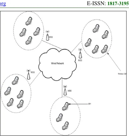
[image:3.612.313.521.76.295.2]In this paper, the proposed algorithm takes in consideration these constraints based on the same system model used in [1] which we represent it as in figure 1, where a host that can move while retaining its network connections is a Mobile Host (MH). The infrastructure machines that communicate directly with the mobile hosts are called Mobile Support Stations (MSS). A cell is a logical or geographical coverage area under an MSS. All MHs that have identified themselves with a particular MSS, are considered to be local to the MSS. An MH can directly communicate with an MSS (and vice versa) only if the MH is physically located within the cell will be served by the MSS, and each MH belongs to only one cell at time.
Figure 1: System Model
4. ADAPTATION DYNAMIC
SYNCHRONIZER ALGORITHM FOR MSS (ADRS)
In this section, another version of the dynamic synchronizer algorithm; in which nodes are MSSs not MHs. A MH that needs to access a CS sends its request to its local MSS, which then inserts it at the tail of a request queue. If that MH was the first in the request queue the MSS initializes a REQUEST message and sends it to its neighbor, it become in WAITING state, and continue working. It may receive other requests for the CS from other MHs in its region, which it adds to the tail of the request queue. When the WAITING MSS eventually receives a GRANT message, it moves all MHs in the request queue to a grant queue, where they are allowed to enter the CS sequentially. After servicing all MHs in the grant queue, the MSS sends a RELEASE message to the SYNCHRONIZER MSS, then the algorithm proceeds in the normal way.
4.1 System Description and Assumptions
4.1.1 Assumptions
The proposed idea was applied on the MSS side to manage the synchronization, also its try to overcome the above limitations for the literature distributed mutual exclusion algorithms mentioned in section 2.
1.All nodes in the system are assigned unique
identification numbers from 1 to N.2.
There is only one requesting process executing ateach node. Mutual exclusion is implemented at the node level.
3.
Processes are competing for a single resource.4.At any time, each process initiates at most one
outstanding request for mutual exclusion.The proposed idea should consider the following aspects about the reliability of the communications [15]:
• Message delivery guaranteed.
• Message-order preservation.
• Message transfer delays are finite, but
unpredictable.
• The topology of the network is known.
Like DRS algorithm , assuming that the nodes in the system are (NR1R, NR2R,…,NRnR) but in this algorithm
it stands for the n MSSs in the system, another system component which is the MHs need also to be considered in this version. So assume we have m
MHs each with a unique identifier (MR1R,
MR2R,…,MRmR).
Also in this version of DRS algorithm we must consider the following assumptions:
1. The nodes (even MH or MSS) have unique node identifiers, (i.e. node i have identifier Ni).
2. A node failure does not occur.
3. Communication links are bi-directional and FIFO.
4. Communication links failures are predictable, providing a reliable communication.
5. A partition in network does not occur.
4.1.2 Description
In this version the MHs need to maintain only 2 data structures:
• Status: CRITICAL, WAITING or REMINDER, as discussed above. Note that a MH cannot be in SYNCHRONIZER state since it is the MSSs that will do synchronization in this algorithm.
• Mss: this contains the address of the local
MSS.
Two new data structures need to be maintained by each MSS in this algorithm:
• Request: which is a queue of MHs; its entries are addresses to MHs that currently requesting the CS in this region.
• Grant: which is a queue of MHs; its entries are addresses to MHs that will enter the CS sequentially in this region.
Three new types of messages that are communicated between a MSS and the MHs in its region are also added:
• MHREQUEST: a MH sends this message to its MSS when it wishes to enter the CS. • MHGRANT: this message is sent by a
MSS to a MH in its region allowing it to enter the CS.
• MHRELEASE: a MH sends this message to its MSS when it exits the CS.
A general snapshot of the system is show in Figure 2. Which describe how the MHs communicate with their local MSS, and How MSSs connected through logical ring.
5. EXECUTION RULES OF THE ADAPTIVE (DRS) ALGORITHM
5.1 Variation from DRS
Handling of some events will differ from the ordinary node DRS, and new events will occur. This is explained through the following rules:
Rule1: Handling a REQUEST message: when a REQUEST message arrives at a node (here node is MSS), it checks its status, if it is not SYNCHRONIZER it simply forwards the message to next. If it is SYNCHRONIZER, the node checks busy, if other node currently uses the CS, SYNCHRONIZER adds the requesting node to the end of the queue.
To add a node to the end of the queue, the SYNCHRONIZER checks its queue pointer, if it is not nil a message is prepared with the address of the requesting node and sent to the node in queue, then queue is set to the address of the requesting process, else, the address of the requesting process is stored in queue. However, if no node is currently CRITICAL, a GRANT message is sent to the requesting node, the address of the requesting node is stored in critical and busy is set to TRUE.
the grant queue. All MHs in the grant queue are then sent a MHGRANT message in turn.
Rule3: Handling a RELEASE message: when the SYNCHRONIZER receives a RELEASE message, it changes its status to REMINDER, sets busy to FALSE, and sends YAS message to the node that completed the CS (i.e. node from which it received the RELEASE message). Together with the message, the SYNCHRONIZER sends the address of the node currently at the end of the queue (current contents of queue), sending nil if no nodes currently in the queue.
Rule4: Handling a YAS message: when a node receives a YAS message, if it is not in REMINDER state, it forwards the message to next, and sends a CHANGE message containing next to critical (note that it knows critical from the YAS message). However, if the node is currently in REMINDER state, it should handle the message. First, it changes its status to SYNCHRONIZER. Then, the node checks the contents of queue, if not nil, a GRANT message is sent to the node in queue and busy is set to TRUE. After that, the node stores the address attached with the message in queue.
Rule5: Handling an ADD message: when a node receives an ADD message, it stores the address in the message in queue.
Rule6: Handling a CHANGE message: when a node receives a CHANGE message, it overwrites its synch to the address in the message.
Rule7: Requesting the CS: when a MH wishes to enter the CS it prepares a MHREQUEST message containing its address and send it to
its local MSS , then waits for a MHGRANT from the MSS.
Rule8: Handling a MHREQUEST message: when a MHREQUEST message arrives at a node, the requesting MH is first added to the tail of the request queue. The node then checks status, if it is WAITING or CRITICAL, nothing is done. If status is REMINDER, the MSS prepares a REQUEST message containing its address and sends it to next, then changes its status to WAITING. If status is SYNCHRONIZER and busy is TRUE, the SYNCHRONIZER send ADD message with the address of itself and sent to the node in next, then queue is set to the address of the SYNCHRONIZER, then SYNCHRONIZER sends a YAS message to the node in next to make it the
SYNCHRONIZER, then it sets status to WAITING. In case that status is SYNCHRONIZER and busy is FALSE, SYNCHRONIZER sets busy to TRUE, stores its address in queue, send MHGRANT message to the requesting MH, sends a YAS message to the node in next and finally changes status to CRITICAL.
Rule9: Handling a MHGRANT message: when a MHGRANT message arrives at an MH, it enters the CS.
Rule10: Exiting CS: when a MH exits the CS, it sends MHRELEASE message to local MSS and changes status to REMINDER.
Rule11: Handling a MHRELEASE message: when a MHRELEASE message arrives at an MSS, it checks grant queue, if not empty the next MH in the queue is sent a MHGRANT message, else, it sends a RELEASE message to the SYNCHRONIZER (using the address stored in synch). And change its status to REMINDER.
Pseudo code
Accordingly, theDRS algorithm in [16] will be modified as follows:
Rule1: When a REQUEST(Nj, Ni) is received by a
node Nj:
•if status ≠ SYNCHRONIZER,
REQUEST(next, Ni).
•if status = SYNCHRONIZER and busy
= FALSE.
•GRANT(Ni, Nj).
•critical = Ni.
•queue = Ni.
•busy = TRUE.
1. if status = SYNCHRONIZER and busy
= TRUE.
•ADD(queue, Ni).
•queue = Ni.
Rule2 & Rule11: When a GRANT(Ni, Nj) is
received by node Ni:
1. synch = Nj.
2. status = CRITICAL.
3. grant = request
4. while grant not empty
• remove Mj from head of grant
•
• MHGRANT(Ni, Mj)
5. RELEASE(synch, Ni).
6.status = REMINDER.
Rule3: When a node Nj receives RELEASE(Nj,
Ni):
• YAS(Ni, nil, queue).
• status = REMINDER.
• busy = FALSE.
Rule4: When a node Nj receives YAS(Nj, Ni, Nk):
1. if status ≠ REMINDER.
• forward YAS(next, Ni, Nk) to next.
• CHANGE(Ni, next).
2. if status = REMINDER.
status = SYNCHRONIZER.
•if queue ≠ nil
•GRANT(queue, Nj).
• busy = TRUE.
• queue = Nk.
Rule5: When a node Ni receives an ADD(Ni, Nj):
1. queue = Nj.
Rule6: When a node Ni receives CHANGE(Ni,
Nj).
1. synch = Nj.
Rule7: When a MH Mi requests access to the CS:
1. status = WAITING.
2. MHREQUEST(Mi, mss).
Rule8: When a node Nj receives
MHREQUEST(Mi, Nj):
1. Add Mi to request.
2. if status = REMINDER.
• REQUEST(next, Nj).
• Status = WAITING.
3. if status = SYNCHRONIZER and
busy = TRUE.
• ADD (next, Ni)
• queue = Ni
• YAS (next, queue)
• Status = WAITING
4. if status = SYNCHRONIZER and
busy = FALSE.
•Busy = TRUE
•queue = Ni
•MHGRANT(Ni, Mj)
•YAS (next, queue)
•Status = CRITICAL
Rule9: When a MH Mi receives MHGRANT(Nj,
Mi):
1. status = CRITICAL. 2. Enter CS.
Rule10: When a MH Mi exits the CS:
1.status = REMINDER.
2.MHRELEASE(Mi, mss).
Rule11: When a node Ni receives
MHRELEASE(Mj, Ni):
1.if grant empty
2.RELEASE(synch, Ni).
3.status = REMINDER
5.2 Example on ADRS
In Figure2, while MSSs receives MREQUEST message from their MHs , MSS1 initiate a REQUEST message that follow the logical ring to MSS2 then to SYNCHRONIZER (MSS3) which in its turn check busy, since there are no nodes (MSSs) currently CRITICAL it send GRANT message to MSS1.
When MSS1 received GRANT message, this will move all MHs in the request queue to grant queue, where they allowed entering the CS sequentially as FIFO based. While MSS1 CRITICAL, MSS3 Receive another REQUEST message
from MSS4, since MSS3 busy flag is true it placed MSS4 in its queue.
6. CORRECTNESS OF THE ALGORITHM
6.1 Mutual Exclusion
To show that the algorithm achieves mutual exclusion, we have to show that two or more nodes can never execute the CS simultaneously; that is, one node exits the CS before the next node can enter the CS. This will be shown by contradiction.
Assume that two nodes Ni and Nj are executing the
CS simultaneously. This means that both nodes have received a GRANT message from the SYNCHRONIZER MSS.
But according to our algorithm, a GRANT massage is sent only by the SYNCHRONIZER(MSS) when it receives a REQUEST message and busy is FALSE, but even if busy is TRUE, the node will wait its turn to enter the CS. So in both cases (no other process is currently in the CS).
6.2 Deadlock Freedom
section, and this can occurs as consequence for any of the following situations:
- either, no node is SYNCHRONIZER or
SYNCHRONIZER node is not aware that other nodes request critical section. As mention above one node must be initiated as SYNCHRONIZER, and while the algorithm is working the YAS message is used to transfer the synchronization state from one node to another. Rule1 in adaptive DRS shows how the SYNCHRONIZER become aware when other nodes require the grant to enter the critical section, it either store the address of requesting node in its queue or send it to the node in its queue when busy true which is in turn serve the waiting, this is applied on both sides either between MSSs or MHs within the cell, so our algorithm is deadlock free.
6.3 Freedom from starvation
Starvation occurs when few sites repeatedly execute their CS while other sites wait indefinitely for their turns to do so. It means that there exists a node (call
Ni) that can enter the CS two or more times before
another node in WAITING state (call Nj) can enter
the CS , but according to the DRS algorithm, when
a node Ni exits the CS, it changes it’s state to
REMINDER, and to enter the CS again it must send a REQUEST message. Using rule 1, if there
are any other node in WAITING state (node Nj),
node Ni will be added to the queue after node Nj.
So, node Nj will enter the CS before node Ni.
Accordingly, there is no starvation.
7. PERFORMANCE ISSUES
The number of messages generated per critical section invocation has traditionally evaluated the performance of most distributed mutual exclusion algorithms. Also, a useful mutual exclusion algorithm is characterized as fair to all nodes in the distributed system, being starvation-free and deadlock-free [2, 13].
Adaptive Dynamic Resource Synchronizer (ADRS) mutual exclusion algorithm reduces the message traffic generated due to CS execution, the number of messages incurred is much lower than in some other algorithms according to system assumptions that illustrated previously, and our implementation results. This is achieved because the nodes within the cell have to send at most three messages, and this happen because the existence of MSS, and there is no logical ring. Every node make a request directly to the Synchronizer which is in its turn
decides to put the node in the queue or grant it the CS.
7.1 Best case performance
If we look to the performance between the MSSs: It happens when the synchronizer is the immediate neighbor from the direction of sending, and no one waiting the resource, in this case:
Number of messages to enter and exit CS =1(REQUEST)+1(GRANT)+1(RELEASE) [16] Suppose the E is the message transfer time, so number of messages will be
= 3E
And waiting time in queue=0 .[16]
- But if we discuss the performance within the cell itself (between MHs): which is done when there is only one node in the MSS queue
So its = 1(MHREQUEST)+1(MHGRANT)+1(MH RELEASE) ,so its 3E in best case.
Waiting time can be calculated as follow: Assume:
M : number of the MHs within the cell Mq: number of the nodes in the queue
T: the time needed to access the CS, we assume that it is fixed for all nodes
At best case there is no nodes in the queue the requester will enter the CS directly so Mq=0. Waiting time = waiting time in queue + execution time in CS
= (Mq*T ) = 0*T =0
7.2 Worst case performance
Again the performance between the MSSs, which is like the MHs in the DRS,It happens when the synchronizer in the far middle of the ring(longest path node),and all other processors want the resource(waiting in queue) and each one of them will use the resource for the longest possible time(max resource use).
Number of messages to enter and exit
CS=1(REQUEST)*(n/2)+(n-1)(GRANT)*(n-1)/2+(n-1)(RELEASE)*(n-1)/2
= E((n/2)+(n-1)(n-1)/2+(n-1)(n-1)/2)
And waiting time in queue=(n-1)*max time for allocating the resource .
- The performance within the cell itself (between MHs): here is the enhancement in performance appeared using the ADRS algorithm,
Number of messages to enter and exit CS = 3E*M
This case happens if all of nodes try to enter the CS at the same time.
Comparing it with the DRS, we notice that the total number of messages will be increased, so the network traffic will be decreased also.
Waiting time in queue = (Mq) *T = (M-1)*T
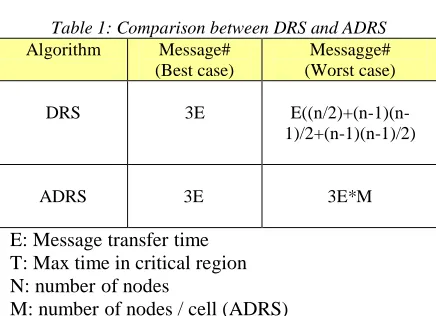
[image:8.612.85.303.269.427.2]These results abbreviated in table 1.
Table 1: Comparison between DRS and ADRS Algorithm Message#
(Best case)
Messagge# (Worst case)
DRS 3E
E((n/2)+(n-1)(n-1)/2+(n-1)(n-1)/2)
ADRS 3E 3E*M
E: Message transfer time T: Max time in critical region N: number of nodes
M: number of nodes / cell (ADRS)
Also, we add a new Characteristic to the network which is the network become incrementally growth. The power energy of the nodes will be saved, because they will not involved in every GRANT or RELEASE process as in DRS algorithm, every node will just send and recieve it's own messages . Just MSS must have the higher energy within the cell.
8. CONCLUSION
We have presented an ADRS mutual exclusion algorithm for mobile networks. We directed the reader to the full proof that this algorithm provides mutually exclusive access to a critical section. We also have developed a technique to improve the fairness of the algorithm, as shown above we proof our algorithm correctness, so no starvation and no deadlock. These key points arise also in our implementation on the algorithm.
We also compared the performance of the ADRS algorithm with the previous version DRS algorithm, to show that this algorithm enhanced the performance when it is reduce the number of messages to be transferred, so it minimize the
traffic load in the network, this is happen because of the MSS existence.
Moreover, using the ADRS the network growth will be achieved and energy saving also.
REFERENCES
[1] Naimi,M. , Trehel,M. and A. Arnold, “A log (N) distributed mutual exclusion algorithm based on path reversal,” Journal of Parallel and Distributed Computing, vol. 4, April 1996, pp. 1–13.
[2] Raymond, K. ,“A Tree based Algorithm for
Distributed Mutual Exclusion”, ACM
Transactions on Computer Systems, vol. 7, February 1989, pp. 61–77.
[3] Raynal, M., “A simple taxonomy for Distributed mutual exclusion algorithms”, ACM SIGOPS Operating Systems Review, vol. 25, 1991, pp. 47-50.
[4] Agarwal ,D. and El Abbadi, A., “An Efficient and Fault–Tolerant Solution for Distributed Mutual Exclusion”, ACM Transactions on Computer Systems, vol.9, February 1991, pp. 1–20.
[5] Maekawa, M. ,“A �N Algorithm for Mutual
Exclusion in Decentralized Systems”, ACM Transaction on Computer Systems, vol. 3, No. 2, 1985, pp. 145–159.
[6] Ricart, G. & Agrawala, A. , “An Optimal Algorithm for Mutual Exclusion in Computer Networks”, Communications of the ACM, Vol. 24 (1), 1981 , pp. 9-17.
[7] Saxena, P.C., Rai, J., A survey of permission-based distributed mutual exclusion algorithms. Computer standards & interfaces, vol. 25, no. 2, 2003,pp. 159-181.
[8] Lamport, L., “Time, Clocks and the Ordering of Events in a Distributed System”, Communications of the ACM, Vol. 2, 1978, pp. 558-565.
[9] Nisho, S. ,K.F. Li and E.G. Manning, “A resilient mutual exclusion algorithm for computer networks”, IEEE Transactions on Parallel and Distributed Systems, vol. 1, 1990,pp. 344–355.
[10] Misra, J. ,“Detecting termination of distributed computations using markers”, Proceedings of the 2nd ACM Annual Symposium on Principles of Distributed Computing, 1985,pp. 237–249.
[12] Chaudhuri, P. and Karaata ,M. “An o(n1/3) algorithm for distributed mutual exclusion. Journal of Systems Architecture”, 1998, 45(5):409{420.
[13] Abhilasha Gupta, B.V.R. Reddy, Udayan Ghosh, Ashish Khanna , “A Permission-based Clustering Mutual Exclusion Algorithm for Mobile Ad-Hoc Networks” , (IJERA) ISSN: 2248-9622 ww.ijera.com Vol. 2, Issue 4, July-August 2012.
[14] Rahman, M. and Akbar, M.,” A Permission Based Hierarchical Algorithm for Mutual Exclusion”journal of computers, vol. 5, no. 12, december 2010
[15] Jennifer Walter, Jennifer Welch and Nitin Vaidya, “A mutual exclusion algorithm for ad hoc mobile network”, In Journal of Wireless Networks, vol. 7, 2001, pp. 585-600. [16] Sharieh, A., M. Itriq and W. Dbabat, 2008. “A