International Journal of Emerging Technology and Advanced Engineering
Website: www.ijetae.com (ISSN 2250-2459, Volume 2, Issue 3, March 2012)13
Horizontal Line and Window Based Stereo Matching
Method
Khyati N.Patel
1, Sameena Zafar
21
P.G.Student , Dept of E & C, Patel College Of Science & Technology, Rajiv Gandhi Praudyogiki Vishvavidyalaya, Bhopal
2SHead of the department of E & C , Patel College Of Science & Technology,
Rajiv Gandhi Proudhyogiki Vishwavidyalaya, Bhopal
1
Abstract—Obtaining reliable disparity maps, indicating
distance of surface from the stereo camera pair, have importance in robotic applications and autonomous systems. Intelligent systems, which can move around by itself, could be developed by obtaining depth information from the sensors. Stereo vision is one of the methods that can yield depth information of the scene. It uses stereo image pairs from two cameras to produce disparity maps that can be easily turn into depth maps. Reliability of depth maps and computational cost of algorithm is key issue for implementing real time robust applications.
Matlab 2007 has been chosen for implementing different Stereo Matching Algorithms. Stereo Matching Algorithms like Matching (Window-Based), Matching (Horizontally Line-Based) have been implemented to generate disparity Map. Matching (Window- Based) and matching (Horizontally Line-Based) gives good disparity Map. Stereo Matching Algorithms are tested on standard images like Tsukuba, Cravon, we can also try for the same images and prepare the experimental real time setup for matching the images. Stereo Matching Algorithm Adaptive Support-Weight Approach for visual correspondence search has been implemented to generated disparity Map. Quality metrics use for evaluating the performance of stereo correspondence algorithms and the techniques used foracquiring our image data sets and ground truth estimates and got comparisons of all algorithm.
Index Terms—Image Processing, Stereo matching,
Window based method, horizontally line based method.
I. INTRODUCTION
In recent years, it is an important research direction applying visual image technology for underwater target & environment detection. With the development of the theory of binocular vision, underwater binocular vision technology has been used in many fields, such as marine resources exploration, underwater target detection, marine ecological environment.
Binocular vision, which is inspired by human visual process, computes the disparity between correspondence points in images captured by two cameras for distance measurement, and then recovers the depth information of the object. Considering the features of underwater environment, basis for applying binocular vision technology can better perceive underwater environment information. It provides the theory robot understanding the underwater environment and realizing the navigation and positioning. The image matching is one of the key technologies to realize underwater binocular vision. And the result of the matching would affect directly the
precision of object recognition and 3D scene
reconstruction.
International Journal of Emerging Technology and Advanced Engineering
Website: www.ijetae.com (ISSN 2250-2459, Volume 2, Issue 3, March 2012)14
Binocular vision is the process of recovering depth from two images with the same height, the same direction and a certain distance, similar to human vision principle. During the process, stereo matching is the key point, which means to find the correspondence pixels of the same physical spatial point on both images. Binocular stereo matching algorithm research falls into two categories. One is based on sparse points, and the other is based on dense points. The latter one is more accurate on image matching. There are many binocular dense-point matching methods in which the representatives are Birch Field algorithm and Yoon algorithm. Birch Field algorithm is used to match two gray-scale images. It applies dynamic programming into matching epipolar lines. It is efficient but inaccurate. Subsequent improvement method of Birch Field is based on each pixel's eight neighborhoods and improves the matching accuracy to some extent. In the study of color image matching, Yoon’s method of adaptive window algorithm is a milestone.
Obtaining reliable depth maps, indicating distance of surface from the stereo camera pair, have importance in robotic applications and autonomous systems. Intelligent systems, which can move around by itself, could be developed by obtaining dept information from the sensors. Stereovision is the one of methods that can yield dept information of the scene. It uses stereo image pairs from two cameras to produce disparity maps that can be easily turn into dept maps.
II. BRIEF REVIEW
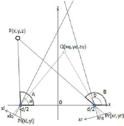
A Stereo matching is another technique that is well known for measure and it is very easy to understand and program. With stereo matching we can get the exact position of a target by two stereo pictures. However the traditional stereo matching needs a strict condition about camera, such as the axis of stereo camera (a pair of camera with the same properties) must be kept parallel and the height of cameras will be the same. These conditions limited the application of stereo matching. The position of a point P in 3D space can be measured by traditional stereo matching that computes the coordinate of P, (x, y, z), from two pictures called left image and right image taken by two cameras separately (Figure 1). Based on the triangulation from two views the axis of the camera lenses must be paralleled to axis z, and the two cameras must be kept the same height, that is, the same y.
FIGURE:1LEFT AND RIGHT IMAGES WITH PROJECTION POINT P
In Figure 1 and 2 the point P is our target we want to know P(x, y, z) exactly. For convenience we only show the x-z plane in Figure 2. Assume that the two cameras have the same focus distance f, the distance between the two cameras is d, pl(xl,yl) denotes the coordinates of P in the left image and pr(xr,yr) denotes the coordinate of P in right image, we can get P(x,y,z) by,
(1)
(2)
(3)
(4)
International Journal of Emerging Technology and Advanced Engineering
Website: www.ijetae.com (ISSN 2250-2459, Volume 2, Issue 3, March 2012)15
(5)
(6)
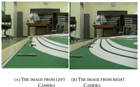
Figure 3(a) and (b) show the left image and the right image taken by two different cameras
(A)THE IMAGE FROM LEFT (B)THE IMAGE FROM RIGHT
CAMERA CAMERA
FIGURE 3.STEREO IMAGES FOR COMPUTATION (TARGETS ARE THE PENS ON THE TABLE)
III. PROPOSED METHODS
Region Based Stereo Algorithms:
a) Global Error Energy Minimization by Smoothing Functions
In this method, we used block-matching technique in order to construct an Error Energy matrix for every disparity. Lets denote left image in RGB format by L(i, j,c) , denote right image in RGB format by R(i, j, c) and error energy by e(i, j, d) . For n m window size of block matching, error energy e(i, j, d) can be expressed by,
where, c represents RGB components of images and takes value of (1,2,3)corresponding to red, blue and green. d is the disparity. For a predetermined disparity search range (w), every e(i, j, d) matrix respect to disparity is smoothed by applying averaging filter many times.
Averaging filter (linear filter) removes very sharp change in energy which possibly belongs to incorrect matching. An other important properties of repeating application of averaging filter is that it makes apparent global trends in energy. (Local filtering in iterations could solve a global total variation optimization problem) Considering global trend in error energy naturally makes this algorithm a region based algorithm. For n m window size, averaging filtering of e(i, j, d) can be expressed by following equation,
(8)
After iterative application of averaging filtering to error energy for each disparity, we selected the disparity ( d ), which has minimum error energy e~(i, j,d) as the most reliable disparity estimation for pixel (i, j) of disparity map. Let’s write basic steps of algorithm more properly,
Step 1: For every disparity d in disparity search range, calculate error energy matrix.
Step 2: Apply average filtering iteratively to every error matrix calculated for a disparity value in
the range of disparity search range.
Step 3: For every (i, j) pixel, find the minimum error energy e~(i, j,d) , assign its disparity index ( d ) to d(i, j) which is called disparity map.
(A)CONSTRUCTION ERROR ENERGY MATRIX
[image:3.612.52.286.227.372.2] [image:3.612.352.539.508.584.2]
International Journal of Emerging Technology and Advanced Engineering
Website: www.ijetae.com (ISSN 2250-2459, Volume 2, Issue 3, March 2012)16
(C)DISPARITY MAP GENERATION BY MINIMUM ENERGY POINTS
FIGURE:4.METHOD USING GLOBAL ERROR ENERGY MINIMIZATION BY SMOOTHING FUNCTIONS
b) Line Growing Based Stereo Matching
Also proposed an algorithm based on region growing. In this manner, we consider region-growing mechanism in two phases operation. First phase, finding root point to grow region (Root Selection process) and the second phase, growing region for a root point corresponding to predefined rule.(Region Growing process) Our rule for associating a point to root point in the growing process is to have lower error energy than a predetermined threshold of error energy (Line Growing Threshold). In our application, being associated to a root points means to have the same disparity by root point. Thereby, the region emerged from all associated points have a disparity value. Actually, we should call the algorithm as disparity growing. Let’s generally express steps of the algorithm in a list,
Step 1: (Root Selection process) Select a point, which isn’t belonging to any grown region and find its disparity using energy function equation (1). Set it root point and set its disparity to region disparity then go to step 2. If you didn’t find any disparity with lower enough error energy, repeat this step for the next point.
Step 2: (Region Growing process) Calculates error energy of neighbor points just for root point disparity, which was called region disparity. If it is lower than the predetermined error energy threshold, associate this point to region.
Step 3: Proceed the Step 2 until region growing any more. In the case that region growing is completed, turn back to step 1 to find out new root point to repeat these steps. When all points in image processed, stop the algorithm. Grown disparity regions composes disparity map d(i, j) .
In order to reduce complexity of the algorithm, we allow the region growing in the direction of rows since disparity of stereo image is only in row directions. So, only one neighbor, which is the point after searched point, is inspected for region growing.
FIGURE:5METHOD USING LINE GROWING
IV. PROBLEM STATEMENT
In our work a number of cameras are located around of target and the two pictures taken by each pair are used for stereo matching calculation. It is impossible to compute the coordinate of target because the axes of camera lens are probably not paralleled each other. Assume these cameras having the same height we proposed a stereo axes correction algorithm and new equations to solve the unparalleled lens axes problem.
(A) (B)
International Journal of Emerging Technology and Advanced Engineering
Website: www.ijetae.com (ISSN 2250-2459, Volume 2, Issue 3, March 2012)17
FIGURE :6.STEREO AXES CORRECTION
FIGURE:7.THE PRINCIPLE OF STEREO AXES CORRECTION
[image:5.612.52.565.111.588.2]The Rubik’s cube both in the left and right images of Figure 6 is our measured target. We do know the two axes of camera lens are not paralleled but we are not sure exactly how much they incline each other. In order to find out the lens axes inclined angle a and b of Figure 7 we pick up a known point Q(xq,yq,zq) as the reference point whose
depth value zq and the distance between camera and Q can
be measured by any measure tool. Figure 8 and (9) gives the method to measure the point Q.
FIGURE :8.THE MEASURE OF THE REFERENCE POINT
(9)
(10)
Now the known Q(xq, yq, zq) into equations, where xlq is
coordinate x of Q in the left image and xrq is coordinate x
of Q in the right image,
(11)
(12)
A and B that are inclined angles of target P in the left image and the right image can be expressed by
(13)
(14)
Therefore the coordinate of target P can be obtained by
(15)
(16)
[image:5.612.51.261.330.544.2]International Journal of Emerging Technology and Advanced Engineering
Website: www.ijetae.com (ISSN 2250-2459, Volume 2, Issue 3, March 2012)18
If the properties of the left camera and the right camera are different, let fl,ml and fr,mrstand for the focus distance
and coefficients m of the left camera and the right camera separately, a, b, A and B are rewritten as follows
(18)
(19)
(20)
(21)
Having the new equations not worry about whether the lens axes of cameras are paralleled or not anymore. And the shadow area of figure become more widely than before, if necessary we can incline leans axes intentionally to get better broad views. Meanwhile in the new method the reference point plays an important role to correct the unparalleled lens axes.
A critical issue in stereo matching is to measure the similarity (dissimilarity) between correspondences, which is calculated as a matching cost. Common matching costs defined based on the brightness constancy assumption, i.e., scene points have similar intensities in different views, are Absolute Difference and Squared Difference. Using the matching cost, many local and global stereo methods have been proposed to improve the matching accuracy, substantially.
Other matching cost functions obtain robustness to radiometric differences by removing or relaxing the brightness constancy assumption. Hirschmuller evaluated many of them such as Normalized Cross-Correlation (NCC) ,rank and census transforms , LoG and mean filters. As a more complicated measure, mutual information
method can handle more complex radiometric
transformations. When globally reasoning the image radiometric transformation, mutual information method is comparably sensitive to local variations such as vignetting.
FIGURE:9.MATCHING THE TSUKUBA (A) LEFT IMAGE AND (B) ITS RIGHT IMAGE WITH A GLOBAL INTENSITY BIAS
V. WORK
The major innovative point is to combine color aggregation with local disparity estimation and adaptive window matching. It is able to accomplish a better matching accuracy while effectively reducing the time complexity thus improves the performance of the algorithm.
Compared with land image, there are more significant differences in underwater image quality. Medium’s strong absorption of light and scattering properties, the underwater image has the characteristics of low contrast, high
ambiguity and low image pixel resolution. In underwater image based on stereo matching algorithm is
already present and here we can see that which output will come if underwater image is based on window-based adaptive correspondence search algorithm but we can use horizontal line based method.
Using window and Horizontal line we use the following steps:
Take the disparity map estimated from the above step as
the initial value, now we use window-based
correspondence method to optimize the result.
For each pixel p and its neighborhood Np in reference
image, the corresponding pixel pdand its neighborhood Np
in target image, define the dissimilarity E (p, p4) between
the two windows:
(22)
Where e (q ,qd) is absolute difference and w( p, q) is the
adaptiveweight:
e(q, = (23)
International Journal of Emerging Technology and Advanced Engineering
Website: www.ijetae.com (ISSN 2250-2459, Volume 2, Issue 3, March 2012)19
∆cpqand ∆gpqare color similarity and geometric proximity.
To better understand depth and disparity relation, let see stereo projection representation illustrated in the Figure 14. By considering the figure, one can derive relation between dept (Z) and disparity (d) by using basic geometrical calculationsasfollowing.
(24)
If real location of object surface projected at pixel (i, j) is willing to calculate, following formulas can be used in calculation of (X ,Y) points after calculation of the Z .
(25)
FIGURE 10.REPRESENTATION OF THE STEREO PROJECTION
In order to obtain smoother depth map to be used in applications such as robot navigation and recent trend for vision in various engineering application.
For that we take a various left and right angle with putting different distance of the camera/webcam and determine the disparity map for image, if time permits then try for real time interface with camera/webcam to computer system and prepare the stereo matching of the images and determine using smoothing with and without consider the reliability of non estimating pixel of images, also determine RMS error, time to be taken for execution in our system.Our work progress chart show in figure 11.
FIGURE:11 WORK PROGRESS CHART
LEFT CAMERAIMAGE RIGHT CAMERAIMAGE DISPARITY MAP
LEFT CAMERAIMAGE RIGHT CAMERAIMAGE DISPARITY MAP
FIGURE:12 WINDOW BASED METHOD IMAGE AND DISPARITY MAP
LEFT CAMERAIMAGE RIGHT CAMERAIMAGE DISPARITY MAP
LEFT CAMERAIMAGE RIGHT CAMERAIMAGE DISPARITY MAP
FIGURE:13HORIZONTAL LINE BASED METHOD IMAGE AND DISPARITY
International Journal of Emerging Technology and Advanced Engineering
Website: www.ijetae.com (ISSN 2250-2459, Volume 2, Issue 3, March 2012)20
VI. CONCLUSION
This paper puts forward a rapid window-based adaptive correspondence search algorithm using mean shift and disparity estimation. The matching time complexity is reduced and the performance of the algorithm is enhanced.
Time (s) Tsukuba Venus Teddy Cones
Yoon’s 1800 2700 3600 3600
Horizontal line based
700 1000 2400 2500
Window based
485 510 830 640
References
[1] Huibin Wang, Hongye Sun, Jie Shen, Zhe Chen, “A Research on Stereo Matching Algorithm for Underwater Image”, 2011 4th International Congress on Image and Signal Processing, 978-1-4244-9306-7/11/$26.00 ©2011 IEEE,pp.850-854.
[2] Shujun Zhang, Jianbo Zhang, Yun Liu, “A Window-Based Adaptive Correspondence Search Algorithm Using Mean Shift and Disparity Estimation”, 2011 International Conference on Virtual Reality and Visualization, DOI 10.1109/ICVRV.2011.47, 978-0-7695-4602-5/11 $26.00 © 2011 IEEE,pp.319-322.
[3] Ningping Sun, Hiroshi Nagaoka , Takuya Shigemoto, “A Correction Algorithm for Stereo Matching with Web Cameras”, 2011 International Conference on Broadband and Wireless Computing, Communication and Applications, DOI 10.1109/BWCCA.2011.88, 978-0-7695-4532-5/11 $26.00 © 2011 IEEE,pp.543-548.
[4] Jian Wei, Shigang Wang, Liwei Chen, Tianxiao Guan, “Adaptive Stereo Video Object Segmentation Based on Depth and Spatio-Temporal Information”, 2009 World Congress on Computer Science and Information Engineering, DOI 10.1109/CSIE.2009.422,978-0-7695-3507-4/08 $25.00 © 2008 IEEE,pp. 140-144
[5] M. Kaaniche, W. Miled, B. Pesquet-Popescu, A. Benazza-Benyahia and J.- C. Pesquet, “Dense Disparity Map Representations For Stereo Image Coding”, ICIP 2009,978-1-4244-5654-3/09/$26.00 ©2009 IEEE,pp.725-728.
[6] Barıs Baykant ALAGÖZ, “Obtaining Depth Maps From Color Images By Region Based Stereo Matching Algorithms”, OncuBilim Algorithm And Systems Labs. Vol.08, Art.No:04,(2008),pp.1-13.
[7] Andrea Fusiello, Emanuele Trucco, Alessandro Verri, “A compact algorithm for rectification of stereo pairs”, Machine Vision and Applications (2000) Springer-Verlag 2000, pp.16–22.
[8] Ke Zhang, Jiangbo Lu,Gauthier Lafruit1, Rudy Lauwereins,Luc Van Gool, “Robust Stereo Matching With Fast Normalized Cross-Correlation Over Shape-Adaptive Regions”, ICIP 2009, 978-1-4244-5654-3/09/$26.00 ©2009 IEEE,pp.2357-2360.
[9] N. Grammalidis and M.G. Strintzis, “Disparity and Occlusion Estimation in Multiocular Systems and their Coding for the Communication of Multiview Image Sequences,” IEEE Trans. Circuits and Systems for Video Technology, vol. 8, no. 3, pp. 328– 344, June 1998.
[10]N. Grammalidis and M.G. Strintzis, “Disparity and Occlusion Estimation in Multiocular Systems and their Coding for the Communication of Multiview Image Sequences,” IEEE Trans. Circuits and Systems for Video Technology, vol. 8, no. 3, pp. 328– 344, June 1998.
[11]Geoffrey McLachlan and Thriyambakam Krishnan. The EM Algorithm and Extensions. John Wiley & Sons, New York, 1996.
[12]L. Hong and G. Chen. Segment-based stereo matching using graph cuts. In CVPR, pages I: 74–81, 2004.
[13]M. Bleyer and M. Gelautz. A layered stereo matching algorithm using image segmentation and global visibility constraints. ISPRS Journal of Photogrammetry and Remote Sensing, 59(3):128–150, May 2005
[14]J. Sun, N. Zheng, and H. Shum. Stereo matching using belief propagation. In ECCV, page II: 510 ff., 2002.